Dynamic lighting and an unlimited number of arbitrary sources in 2D
Continuing the theme of cycling, I want to share how I did the lighting in a pixel-art toy.
The peculiarity of this method is that these light sources are not limited to either the amount or the form .
Conventionally, the algorithm can be divided into two components: the illumination of 2D objects and the shape of the light sources.
Partly about the lighting written in this post.
In order to determine the intensity of illumination of each pixel, it is necessary to know the normal of this pixel and the direction vector to the light source. Actually here is the division of my post into two parts: where to get the normal pixel (the current object) and how to calculate the direction vector of the light.
As a rule, the normal pixel of the current object is taken from the normal map .
You can get the map of normals in different ways (one of them is described in the above post), I create it like this:
sprite is drawn:
')

Next, a height map is drawn for it. In my case, the sprite itself can be interpreted as a height map. The fact that such a height map and in general about the bump mapping in general can be read here .
On the height map it is already possible to build a normal map. There are several utilities that can do this. I used the plugin for GIMP (here are the examples , but there seems to be ubuntas in the standard repositories).

So, we have both sprites to create the effect of a three-dimensional object. Consider the shader, which using these two sprites and the direction of the light source determines the pixel intensity, at this stage it is exactly the same as in my previous post .
This technology is vaguely reminiscent of Deferred Shading.
The main idea is to create a separate buffer for lighting, where each pixel stores the value of the light intensity for the corresponding pixel in the frame. In other words, this is a regular lightmap for a 2D scene.
In order to make a lightmap, you just need to render all the sources of light into it. The advantages of this approach:
Here, for example, lightmap scene with lava:

This is not a new lighting technique and it has a minus - the lack of a vector of light direction. However, you can come up with an algorithm that would define this vector.
To begin with, we will determine what the light source is and what properties it has. I will not give complex formulas and quotes from a textbook on physics - all this is boring and not interesting. I will try to explain as I would explain to my mother.
So the farther the rays of light come, the weaker their intensity. This observation can be used to determine the direction vector of the light rays. That is, if we have two neighboring pixels and in the first of them the light value is 0.5, and in the second 0.25, then we can conclude that the vector of the light beam is directed from the first pixel to the second.
In this case, a simple formula for calculating the luminance vector is:
v [cx] [cy] .x = p [cx] [cy] .x - p [cx + 1] [cy] .x
v [cx] [cy] .y = p [cx] [cy] .y - p [cx] [cy + 1] .y
where cx, cy - coordinates of the considered pixel
However, the difference between two adjacent pixels may be extremely small, respectively, the length of the vector may also be small and not accurate, so in this case the lighting may seem "flat." I found two solutions to this problem: multiply the result by a certain factor or take pixels spaced 1 or more pixels apart. In the second case, we sacrifice lighting detail. As a result, I combined both of these methods and the final formula looks like this:
v [cx] [cy] .x = (p [cx-d / 2] [cy] .x - p [cx + d / 2] [cy] .x) * k
v [cx] [cy] .y = (p [cx] [cy-d / 2] .y - p [cx] [cy + d / 2] .y) * k
where k is the gain vector of the direction of light, d is the distance between pixels on the basis of which the direction vector is considered.
These new values can either be written to a separate light normal map or calculated on the fly during the rendering of the resulting frame simply by using a lightmap. I chose the second option.
Video demonstrating the effect: the light source is a sprite of arbitrary shape , each lava particle is a light source .
The peculiarity of this method is that these light sources are not limited to either the amount or the form .
Conventionally, the algorithm can be divided into two components: the illumination of 2D objects and the shape of the light sources.
Lighting
Partly about the lighting written in this post.
Spoiler
I was even surprised when I saw this post, because I use the same technique. Of course, normal mapping has long been known, but as far as I know, in pixel art, it began to be used quite recently, I would even say that this is one of the first posts.
In order to determine the intensity of illumination of each pixel, it is necessary to know the normal of this pixel and the direction vector to the light source. Actually here is the division of my post into two parts: where to get the normal pixel (the current object) and how to calculate the direction vector of the light.
As a rule, the normal pixel of the current object is taken from the normal map .
You can get the map of normals in different ways (one of them is described in the above post), I create it like this:
sprite is drawn:
')
Next, a height map is drawn for it. In my case, the sprite itself can be interpreted as a height map. The fact that such a height map and in general about the bump mapping in general can be read here .
On the height map it is already possible to build a normal map. There are several utilities that can do this. I used the plugin for GIMP (here are the examples , but there seems to be ubuntas in the standard repositories).
So, we have both sprites to create the effect of a three-dimensional object. Consider the shader, which using these two sprites and the direction of the light source determines the pixel intensity, at this stage it is exactly the same as in my previous post .
Code
// varying vec4 texCoord; void main(){ gl_Position = gl_ModelViewProjectionMatrix*gl_Vertex; texCoord = gl_MultiTexCoord0; } // uniform sampler2D colorMap; uniform sampler2D normalMap; varying vec4 texCoord; uniform vec2 light; uniform vec2 screen; uniform float dist; void main() { vec3 normal = texture2D(normalMap, texCoord.st).rgb; normal = 2.0*normal-1.0; vec3 n = normalize(normal); vec3 l = normalize(vec3((gl_FragCoord.xy-light.xy)/screen, dist)); float a = dot(n, l); gl_FragColor = a*texture2D(colorMap, texCoord.st); } Sources of light
This technology is vaguely reminiscent of Deferred Shading.
The main idea is to create a separate buffer for lighting, where each pixel stores the value of the light intensity for the corresponding pixel in the frame. In other words, this is a regular lightmap for a 2D scene.
In order to make a lightmap, you just need to render all the sources of light into it. The advantages of this approach:
- The number of light sources is limited only by iron. For example, 1000 light sources are 1000 sprites. Rendering 1000 sprites is not difficult even for a mobile GPU, and is there a need for 1000 sources in a 2D scene?
- light sources can be of different colors and different degrees of transparency - this is a common texture
- the shape of the light sources can be any
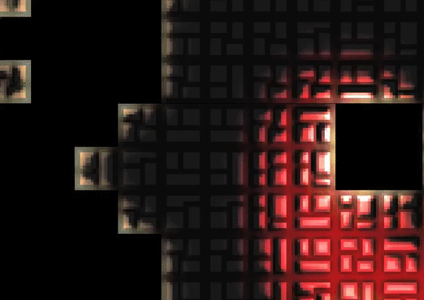
Here, for example, lightmap scene with lava:
This is not a new lighting technique and it has a minus - the lack of a vector of light direction. However, you can come up with an algorithm that would define this vector.
To begin with, we will determine what the light source is and what properties it has. I will not give complex formulas and quotes from a textbook on physics - all this is boring and not interesting. I will try to explain as I would explain to my mother.
So the farther the rays of light come, the weaker their intensity. This observation can be used to determine the direction vector of the light rays. That is, if we have two neighboring pixels and in the first of them the light value is 0.5, and in the second 0.25, then we can conclude that the vector of the light beam is directed from the first pixel to the second.
In this case, a simple formula for calculating the luminance vector is:
v [cx] [cy] .x = p [cx] [cy] .x - p [cx + 1] [cy] .x
v [cx] [cy] .y = p [cx] [cy] .y - p [cx] [cy + 1] .y
where cx, cy - coordinates of the considered pixel
However, the difference between two adjacent pixels may be extremely small, respectively, the length of the vector may also be small and not accurate, so in this case the lighting may seem "flat." I found two solutions to this problem: multiply the result by a certain factor or take pixels spaced 1 or more pixels apart. In the second case, we sacrifice lighting detail. As a result, I combined both of these methods and the final formula looks like this:
v [cx] [cy] .x = (p [cx-d / 2] [cy] .x - p [cx + d / 2] [cy] .x) * k
v [cx] [cy] .y = (p [cx] [cy-d / 2] .y - p [cx] [cy + d / 2] .y) * k
where k is the gain vector of the direction of light, d is the distance between pixels on the basis of which the direction vector is considered.
These new values can either be written to a separate light normal map or calculated on the fly during the rendering of the resulting frame simply by using a lightmap. I chose the second option.
Shader
// varying vec4 texCoord; varying vec4 nmTexCoord; varying vec2 lightMapTexCoord; // varying vec2 lightMapTexCoordX1; // varying vec2 lightMapTexCoordX2; // varying vec2 lightMapTexCoordY1; // varying vec2 lightMapTexCoordY2; // //, , . uniform vec2 fieldSize; // const float spriteSize = 16.0; // void main() { gl_Position = gl_ModelViewProjectionMatrix*gl_Vertex; texCoord = gl_MultiTexCoord0; nmTexCoord = gl_MultiTexCoord1; // . lightMapTexCoordX1 = vec2(gl_Vertex.x/(fieldSize.x-1.0/spriteSize), gl_Vertex.y/fieldSize.y); lightMapTexCoordX2 = vec2(gl_Vertex.x/(fieldSize.x+1.0/spriteSize), gl_Vertex.y/fieldSize.y); lightMapTexCoordY1 = vec2(gl_Vertex.x/fieldSize.x, gl_Vertex.y/(fieldSize.y-1.0/spriteSize)); lightMapTexCoordY2 = vec2(gl_Vertex.x/fieldSize.x, gl_Vertex.y/(fieldSize.y+1.0/spriteSize)); lightMapTexCoord = vec2(gl_Vertex.x/fieldSize.x, gl_Vertex.y/fieldSize.y); } //--------------------------------------------------------------------------------------------------------------- // varying vec4 texCoord; varying vec4 nmTexCoord; varying vec2 lightMapTexCoord; varying vec2 lightMapTexCoordX1; varying vec2 lightMapTexCoordX2; varying vec2 lightMapTexCoordY1; varying vec2 lightMapTexCoordY2; uniform sampler2D colorMap; // uniform sampler2D lightMap; uniform float ambientIntensity; // uniform float lightIntensity; // const float shadowIntensity = 8.0; // const vec3 av = vec3(0.33333); // void main() { vec4 lmc = texture2D(lightMap, lightMapTexCoord)*2,0; // . , 0.5, 1.0 (). , , . , . // x y - float x = (dot(texture2D(lightMap, lightMapTexCoordX1).rgb, av)- dot(texture2D(lightMap, lightMapTexCoordX2).rgb, av))*shadowIntensity; float y = (dot(texture2D(lightMap, lightMapTexCoordY2).rgb, av)- dot(texture2D(lightMap, lightMapTexCoordY1).rgb, av))*shadowIntensity; float br = dot(lmc.rgb, av); // - vec3 l = vec3(x, y, br); // , z , , , l = normalize(l)*br; // vec3 normal = 2.0*texture2D(colorMap, nmTexCoord.st).rgb-1.0; float a = dot(normal, l)*lightIntensity; a = max(a, 0.0); vec4 c = texture2D(colorMap, texCoord.st); c = a*min(c, lmc)+ambientIntensity*c; // float m = 0.0; // , , (. gif ). . m = max(m, cr); m = max(m, cg); m = max(m, cb); gl_FragColor = c+max(0.0, m-1.0); // . } Video demonstrating the effect: the light source is a sprite of arbitrary shape , each lava particle is a light source .
Source: https://habr.com/ru/post/183534/
All Articles