USB support in KolibriOS: what's inside? Part 3: Host Controller Support Code
 The support level of host controllers, as I wrote in the general overview , should cause higher levels when certain events occur and provide the functions necessary for higher levels to work.
For convenience, I will talk about the various elements of the support code in the order in which they receive control.
Starting USB Subsystem
Preparation: USB controllers in the list of PCI devices
The USB subsystem is started by calling
usb_init from init.inc during system boot.By the time USB is launched, a list of
pcidev_list PCI devices found has already been prepared. USB controllers are recognized among all PCI devices by class code, subclass, and interface:| Type of | Class | Subclass | Interface |
|---|---|---|---|
| Uhci | 0Ch | 03h | 00h |
| OHCI | 0Ch | 03h | 10h |
| EHCI | 0Ch | 03h | 20h |
| Xhci | 0Ch | 03h | 30h |
usb_init passes through the list of PCI devices several times, each time allocating USB controllers.')
Disable BIOS control
Some BIOSes can handle USB mice, USB keyboards and USB flash drives, providing data for operating systems that do not know about USB. Data from mice and keyboards is converted into PS / 2 format and in one way or another is brought to the operating system in the same way as if a real PS / 2 mouse and / or keyboard existed in the system. A USB flash drive seems to be a hard disk from the point of view of
int 13h — such support is found more often than mouse support, since it is necessary for booting from flash drives.The operating system can use any processor mode and independently handle any interrupts. So that the BIOS in such conditions could still get control with a predictable environment, still around 486 (starting with the special i386SL version, to be exact), Intel came up with a special System Management Mode (SMM) processor, in which the BIOS works, interrupting the operating system the system. It is impossible to get into SMM using the processor itself; The processor enters this mode when the motherboard hardware gives a special signal to the System Management Interrupt (SMI) . USB controllers embedded in the chipset, as a rule, can generate SMI instead of interruption, depending on the settings.
The first pass through the
pcidev_list list is used to tell the BIOS that USB controllers are under the control of the operating system, so the BIOS should no longer do anything with them.It is important that on this aisle all companions are processed to a pair of EHCI controller. For example, bypassing in ascending order of PCI coordinates guarantees this. In the first versions of the code, this pass was not separately allocated, and all EHCI controllers were processed first; This worked on many configurations, but during the tests it turned out that not all BIOSes were written correctly and that the wrong order could cause the system to hang inside the SMM. More specifically, the following scenario is possible:
- The BIOS detects a stop request with EHCI;
- BIOS deconfigures the controller and forgets about it;
- possession of ports passes to the partner;
- A flash drive connected to the port also goes to the companion;
- a companion signals a new device;
- since the companion is still under the control of the BIOS, she considers the device her own, finds out what kind of device it is; sees an old flash drive;
- and it turns out that the BIOS remembers the USB flash drive that it was located on the controller, which the BIOS successfully forgot about. Attempting to use the data of a forgotten controller quickly leads to a sad end.
The method of reporting the BIOS that it is time to return the controller depends on the controller. The corresponding functions are called
{u,o,e}hci_kickoff_bios . UHCI, being the chronologically first interface, does not provide a special message, so uhci_kickoff_bios simply turns off SMI generation and stops the controller. In OHCI and EHCI, the procedure for communicating with the BIOS is theoretically described in the specification, but practically ... there are some details. In both cases, the procedure is as follows: set a certain bit in a register and wait for the desired state of the other bit; if the BIOS works with the controller, the controller will generate SMI, the processor will go to the SMM and cause the BIOS, the BIOS will untie the controller, change the other bit to the desired state and exit the SMM. The detail of the procedure for OHCI is that, as it turned out during the tests , the BIOS may well leave the controller with interrupt sources enabled; if any event generates an interrupt and the interrupt is unmasked in the interrupt controller before the OHCI driver sets its handler, the system will again hang - the OHCI will generate the interrupt again and again, which cannot be processed. Therefore, ohci_kickoff_bios disables interrupts during a conversation with the BIOS and turns off all OHCI interrupt sources at the end of a conversation. In EHCI, in fact, it is impossible to immediately set the bit “the operating system has requested ownership of the controller,” you first need to check that the BIOS owns the controller; Some BIOSes “release” the controller and forget about it even before booting the system, do not clear the SMI generation bits and cannot process the request - the system will hang again due to the SMI generated again and again.Controller initialization
If, on the first pass,
usb_init does not detect USB controllers, it stops its operation. If there are USB controllers, then usb_init creates a stream allocated for USB processing and makes two more passes through the list of PCI devices, calling usb_init_controller for each USB controller, passing the pointer to the corresponding usb_hardware_func structure in usb_hardware_func . The second pass processes the EHCI, the third passes UHCI and OHCI. Here, the EHCI is processed in front of the partners, so that the HS devices are immediately under the control of the EHCI instead of signaling the companion about themselves and immediately being taken away from it.The
usb_init_controller function is in hccommon.inc . It allocates memory for a couple of structures *hci_controller / usb_controller , initializes both of them with zeros, initializes some usb_controller fields, among which should be noted the HardwareFunc , indicating usb_hardware_func . Further, it also calls the controller-specific initialization usb_hardware_func.Init . If no error occurred, then the last action of usb_init_controller registers the controller in the general list of usb_controllers_list and wakes up the USB stream so that it can update the information about the next wake-up time.The specific initialization
usb_hardware_func.Init does the following:- sets up channel groups and relationships between them, including a binary tree of interrupt channels;
- installs a controller interrupt handler
*hci_irq; - writes the correct values to the registers of the host controller, including writing the physical address of the structure
*hci_controller; - calculates the number of ports of the
usb_controller.NumPortsroot hub and provides power to all ports.
The binary tree of interrupt channels has the same structure on all controllers, I described it in the previous article . Communications between channels of other types depend on the controller.
Channel Link: UHCI
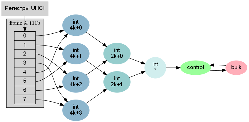
UHCI is chronologically the first controller with the simplest hardware. It has only one register-pointer
UhciBaseAddressReg pointing to the table included in the uhci_controller . Each frame iron loads the corresponding element of the table and starts following the links. The latest in the chain of periodic transmissions is the list of interrupt channels processed by each frame. From the last channel of the list, the link leads to the first channel in the list of control programs. All channels of control transmissions and transmissions of data arrays are connected in a ring. When the controller finishes processing all non-periodic channels, it returns to the beginning of the list of non-periodic channels; With this scheme, a new non-periodic transmission begins to be processed immediately, without waiting for the next frame.The obvious advantage of this scheme is the simplicity of hardware, while fully complying with the requirements of the USB specification for processing priorities. Minuses: with a large load, when the controller does not have time to process all transmissions to the end of the frame, the channels of the same type are unequal - those who are lucky enough to be at the top of the list have a significant advantage - and at low loads the controller is constantly busy reading from memory only for to make sure that there is no new job. The developers of the following controllers took into account the disadvantages of UHCI.
Channel Link: OHCI

OHCI has seven pointer registers, six of which are connected to channels. One of the
OhciHCCAReg registers points to the periodic channel table, similar to the other controllers (with corrections for isochronous transfers), the second OhciPeriodCurrentEDReg indicates the current periodic channel and is not so interesting that it is not even shown in the diagram.Control channels and channels of data arrays are collected in independent lists. Each list has two pointers: a pointer to the top of the
Ohci{Control,Bulk}HeadEDReg and a pointer to the current Ohci{Control,Bulk}CurrentEDReg . The controller can move through the three lists independently of each other; The priorities of the lists are in accordance with the requirements of USB. Each frame controller runs through the list of periodic channels, but, unlike UHCI, it does not lose its position in the other lists, therefore, within the limits of one list all channels are equal; this closes the first minus of the UHCI. The OHCI registers also have two bits “there is a new transfer in the list”, one for the list of control channels, the second for the list of channels of data arrays, the software must set the corresponding bit when adding a new transfer. When the controller starts to go through the list, it clears the bit. When the controller reaches the end of the list, it looks at the bit; if the bit is set, the controller goes to the top of the list, otherwise it stops processing the list. This closes the second minus UHCI.Links between channels: EHCI

EHCI is limited to two pointer registers. One of them,
EhciPeriodicListReg , points to a table of periodic channels, similar to other controllers. Another, EhciAsyncListReg , points to the current non-periodic channel. All non-periodic channels are closed in a ring, now it is a prerequisite, unlike UHCI, where it is one of the possible implementations. Walking along the periodic and non-periodic channels do not depend on each other, which makes all non-periodic channels equal. The requirement for the privilege of control channels to the channels of the data arrays Intel decided to ignore here. In order for the controller, in the absence of operation in non-periodic channels, not to be too keen on endless readings from memory, one of the channels in the ring is marked as the “beginning” of the ring; when the controller meets the “beginning” of the ring a second time without detecting active gears, it stops processing the ring for a while.Work with USB device
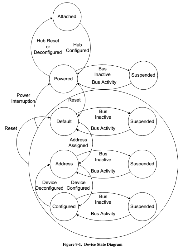
Picture from the USB specification, describing various states of the device and transitions between them:
Device connection
During initialization, the OHCI and EHCI controllers are configured to generate an interrupt when the device is connected and disconnected. Unfortunately, there is no such possibility in UHCI, therefore, if there is a UHCI controller, the USB stream periodically wakes up on its own and polls the controller ports, checking for changes in the connection status. The polling interval is
UHCI_POLL_INTERVAL timer ticks, which is 1 second for the current value.The connected USB device begins interacting with the host controller in the Powered state.
Initialization of a new USB device starts with ... a pause of 100 milliseconds. Since USB devices are connected dynamically, when connected, it is possible to bounce contacts and several consecutive connecting / disconnecting events. With each new event on the same port, the time countdown is restarted. When the Powered state lasts for 100 milliseconds in a row, the connection is considered stable and the code proceeds to the next stage of initialization
*hci_new_port .For the reason about which I will tell a bit later, the next several stages of connection processing cannot be carried out for several devices in parallel. Therefore, before the next stage, the new USB device may have to wait until the current device passes all these stages. The end of the wait is marked with
*hci_new_port.reset , which is part of the internal function *hci_new_port in case the wait turned out to be unnecessary, and simultaneously brought into the interface for higher levels of usb_hardware_func.InitiateReset .Further, the code
*hci_new_port.reset controller to activate the reset signal for the port of the new device. According to the specification, the reset should last at least 10 milliseconds. OHCI counts the time on its own, at the end of the interval it turns off the reset signal and generates an interrupt, the handler of which signals the USB stream to proceed to the next stage. In UHCI and EHCI, you need to count the time programmatically. In order not to load the processor with an idle standby cycle, the USB stream, after turning on the reset signal, schedules a wake-up timer and falls asleep. The timer in KolibriOS ticks with a frequency of 100 Hz, once every 10 milliseconds. To ensure that you get a minimum of 10 milliseconds of reset, the code waits for two countdowns of the timer. After the second tick of the timer, the code turns off the reset signal for the port of the new device, *hci_port_reset_done , and proceeds to the next stage.In USB2, the speed of the device is determined during the reset process. I recall from the previous part that EHCI can work only with HighSpeed devices, and all devices operating at one of the USB1 speeds should be directed to the USB1 companion or hub. From a programmatic point of view, after the end of the reset, EHCI either permits data transfer to the port or not. If, after resetting, the port remains prohibited, it means that the connected device does not work at USB2 speed. In this case, it remains only to inform the logic of the choice of the owner about the port forwarding to the companion; after that, the companion will see the normal connection event and process it.
After a reset, many devices are ready to be configured at higher levels. But not all. The specification requires a pause of at least 10 milliseconds after the reset, and, as tests show, some devices really need this pause. Similar to the previous step, the USB stream falls asleep by two timer counts, this time for all controllers, including OHCI.
After a reset and a subsequent pause, the device transitions from the Powered state to the Default state — one of two “half-working” states, when the device is already ready to receive and send data for the zero end point, but not yet fully initialized. In the Default state, the device responds to the zero address on the USB bus. This is the reason why it is impossible to perform a reset for two devices in parallel: otherwise, two devices would turn out, each of which would have thought that the subsequent setting relates specifically to it.
The zero end point of the device is ready for operation, it's time to open the channel. The channel structure contains the characteristics of the channel itself — for example, its type — and the device characteristics: device speed, device address on the bus, pointer to
usb_controller . The code *hci_port_init , called at this stage, delegates the work of the function *hci_new_device , rendered to the API for hubs usb_hardware_func.NewDevice . The latter prepares a pseudo-channel structure in which the characteristics of the device are correctly filled, and the values of the characteristics of the channel do not matter. With this, the host controller support code finishes independent actions and transfers control of the usb_new_device function usb_new_device the logic device level; further until the device is turned off, the host controller support code only executes requests from higher levels.Opening a channel and channeling
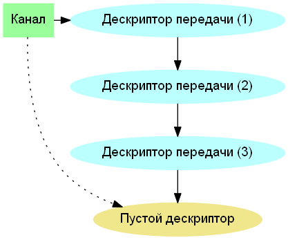
From the controller's point of view, the transmission descriptor queue (one descriptor can describe the whole transmission, or some part, depending on the controller) is organized as a simply linked list, the physical address of the first descriptor is in the channel structure, the physical address of the next descriptor is in the previous descriptor. When the controller finishes processing one descriptor, it updates the channel structure by writing the address of the next descriptor there. It follows that with a running transmission queue, the host controller support code cannot update the address of the next descriptor itself to avoid a race condition with hardware. To organize work, you need an extra empty handle at the end of the queue. An empty handle is marked as inactive for the controller. When the code wants to add a descriptor, it fills the current empty descriptor, selects the next empty descriptor, puts a reference to the new one in the old descriptor, activates the old descriptor with the last action - and all this without intersections on the record with the controller. When the controller reaches the inactive handle, it stops processing the queue, leaving a link to the inactive handle in the channel structure.
After realizing the need for an empty descriptor, opening a channel and placing programs in a queue is fairly straightforward. When opening a
usb_hardware_func.InitPipe = *hci_init_pipe you need:- copy device characteristics from an existing channel or pseudo-channel,
- fill the channel characteristics based on the transmitted data,
- register in the channel structure the physical address of an empty descriptor,
- initialize an empty handle as inactive,
- The last action is to insert the channel into the appropriate list.
usb_hardware_func.AllocTransfer = *hci_alloc_transfer , which is called twice or three times for control transfers, and activating the transfer usb_hardware_func.InsertTransfer = *hci_insert_transfer . AllocTransfer , . InsertTransfer .IOC, Interrupt on completion. IOC, . - .
OHCI - , ( IOC) : , .
ohci_controller , , . OHCI «» , .UHCI EHCI , UHCI EHCI , , , .
USB,
*hci_process_finalized_td . — , ; . — , callback- , .. , , — ( « » ). ,
usb_hardware_func.SetDeviceAddress : . , usb_hardware_func.SetEndpointPacketSize : . UHCI — , , . , . , . EHCI , , , . , : , , , , .OHCI EHCI , , . , . OHCI . EHCI Interrupt on Async Advance Doorbell : « , » . , . , .
: — OHCI EHCI, UHCI —
usb_device_disconnected , . , 100 , .1:
2: -
3: -
4:
5:
6:
Source: https://habr.com/ru/post/183284/
All Articles