USB support in KolibriOS: what's inside? Part 2: Basics of working with host controllers

Before explaining the support code of the host controllers, you need to talk about some of the principles of iron, as well as the data structures used. As I found out when writing text, one article about the whole level of support for host controllers would have turned out to be too big, so the second part of the cycle - which you are reading now - talks about what you need to know to understand the code, and the description of the actions occurring in the code I'll postpone to the next part.
Interrupts and streams
Host controllers notify the software about the events, generating interrupts. An interrupt can come and tear the processor away from the current task at any time; this imposes strict requirements on the interrupt handler. The interrupt handler cannot take any locks - after all, it is quite possible that the interrupted code has just taken possession of the lock and can no longer release it. The only exception is the spinlock variant, which prohibits interruptions at the time of blocking, but due to the globality of the spinlock effect, it is worthwhile to use it less often for very short code sections. On uniprocessor configurations, this option degenerates into a
cli / sti pair without a spinlock itself, on a multiprocessor inside cli / sti usual spinlock remains. In addition, the interrupt controller blocks the rest with the same or lower priority during the processing of one interrupt.For these two reasons, in KolibriOS, interrupt handlers from USB host controllers transfer most of the work to the dedicated USB kernel stream, and themselves are limited to saying “thank you, signal received” to the host controller. The USB stream itself has the highest priority so that the user applications that are conceived do not interfere with the processing. All functions of the upstream layers that are called from the support level of the host controller work in the context of the USB stream and, as a result, may well use synchronization primitives. A pleasant side effect is the automatic serialization of calls: neither the handler of the completion of the second transfer from the channel queue, nor the DeviceDisconnected function will be called until the handler completes the first transfer from the channel queue, which is a logical API requirement.
')
The USB stream also occasionally wakes up to handle delayed events. An example, which I will talk about in more detail later: after the device connection event, you must wait 100 milliseconds before further processing. In this case, the thread will wake up when it detects a device connection and schedules the next wake up in 100 milliseconds, no longer associated with waking up due to an interrupt.
Data structures
For the host controller support level, the following structures are important: the data structure of the controller
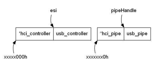
*_controller , the data structure of the channel *_pipe , the data structure of the *_pipe -isochronous transfer *_gtd . Each of them consists of two parts: host controller-specific *hci_* and common for all controllers usb_* . The host controller requires alignment of its structures. The controller data uses page alignment, i.e. 1000h bytes. Alignment of other data is different for different controllers.In KolibriOS, both parts of each structure are arranged in memory in series. The memory for both structures is allocated with one trick taking into account the required alignment. The first in memory is the part responsible for communicating with the host controller to ensure alignment. For the addressing of both parts, a single pointer is used, indicating the boundary between the parts; data on the negative displacements are
*hci_* , on non-negative data - usb_* data. The pointer to usb_controller permanently located in the esi register. The handle of the channel is a pointer to usb_pipe ; one of the usb_pipe fields is a pointer to the corresponding usb_controller .A code that allocates memory for structures must know the sizes of both structures and the required alignment. For
*_controller , a page allocator is used, automatically guaranteeing alignment to the page border. The allocator is called by the code responsible for usb_controller , the size of the structure *hci_controller is taken from usb_hardware_func.DataSize ; as I mentioned in the overview, usb_hardware_func describes things specific to the host controller and the rest of the code.For
*_pipe and *_gtd , it would be extremely wasteful to allocate a page for each instance, and using a common heap of kernels for small blocks is inconvenient due to alignment requirements. Therefore, for them, the code uses an allocator of blocks of a fixed size, which, after selecting the page, cuts it into blocks of a given size and gives them one after another. If the allocated size is multiple, for example, 16 bytes, then all allocated blocks will have an address that is a multiple of 16. Here the allocator needs separate data for each size; in order not to include them all in the usb_hardware_func structure, the latter contains AllocPipe / FreePipe allocation / release FreePipe for a pair of *_pipe and AllocTD / FreeTD structures for a pair of *_gtd structures.The host controller must know the physical addresses of all structures in order to work with them. The address of the structure
*hci_controller entered during controller initialization. The addresses of the data structures of non-isochronous transfers are compiled into a *hci_pipe linked list with the physical address of the first element inside *hci_pipe and the physical address of each next element inside *hci_gtd .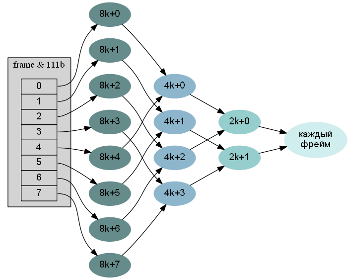
Channels are grouped into several lists. Within each list there are three links: the physical address of the next channel for hardware, the virtual addresses of the next and previous channels for software. One list consists of all channels for control transmissions. The other list consists of all channels for the transmission of data arrays.
The interrupt channel lists are organized in a binary tree as shown in the figure, where circles represent interrupt channel lists, and arrows are the physical addresses of the following elements. The host controller starts each unit of time (the frame for UHCI and OHCI, the microframe for EHCI) by taking the lower n bits of the frame number (the frame, even if it is EHCI), takes the corresponding element of the address table, which is part of
*hci_controller , and starts following links to the next item. The first list, therefore, will be processed once every 2 n milliseconds. Next, the pairs of links “stick together”: the following list leads to two links so that the next list receives the attention of the controller twice per full cycle in the address table, once every 2 n-1 milliseconds. At the end is a list, the elements of which are processed every millisecond. Such an organization of interrupt channels allows you to implement channels with a processing interval, expressed in milliseconds by a power of two. The USB specification allows the actual polling interval to be less than the requested one.In EHCI, the planning unit is the microframe, which is 8 times smaller than the frame. However, walks through the channel lists are still guided by the frame number. Therefore, in each interrupt channel there is a bit mask of 8 bits, in which each bit corresponds to one microframe inside the frame, the zero value of the bit leads to an immediate continuation of the walk through the links. In some channels of such masks there are even two, not intersecting in single bits, but more on that later.
Support for isochronous transfers is under development, so for now I will say only a few words about the hardware. In OHCI, isochronous transfers are addressed in the same way as the others: there is a bit in
ohci_pipe is responsible for the format of the transmission data structures, isochronous and the rest use a different format. In UHCI and EHCI, the data structures for isochronous channels are not as such, and the structures of isochronous transfers are inserted into the address table along with the structures of the interrupt channels. In order for the controller to understand whether the address indicates a channel or an isochronous transfer (of which there are actually two different types), two bits of the address are allocated to the type of structure that is located at this address. As a result, the number n for UHCI and EHCI is 10, but not to support polling intervals more than a second, but so that after processing an isochronous transfer fragment, the software has a second to query the next fragment. In OHCI, n = 5.Transfers and transactions
Although the USB architecture protocols below transfers are almost uninteresting, there are some things that you still need to know about them when implementing levels below the driver level.
The size of the USB bus is almost unlimited; That one device did not occupy the bus too for a long time, transfers are divided into transactions . In one transaction, the next piece of data of limited length is transmitted. The maximum transaction length is one of the characteristics of the channel. For one transfer stage (I remind you that control transfers consist of two or three stages, and the rest are from one stage) all transactions, except the last, have a maximum size; The last transaction transfers the remaining data and may be shorter than the rest.
The size of the data that one pair of
*_gtd structures can describe is also limited. If all data does not fit into one *_gtd , the transfer should be divided into several parts. The partitioning points must be chosen so that, from the device’s point of view, what is happening remains one transfer, that is, the size of all parts except the last must be divided by the maximum transaction size.UHCI is chronologically the first interface created by Intel; UHCI focuses on the simplicity of the hardware implementation. As a result, the UHCI controller knows nothing about transfers, and one
uhci_gtd structure describes one transaction. For large transfers, this leads to a large overhead of separate memory for all transactions.In OHCI and EHCI, the controller is already able to independently break long transfers into transactions, here the restrictions are weaker. In
ohci_gtd there are two fields for two data pages, at best, it turns out 2000h bytes, at worst (if the data starts with the address xxxxxFFFh ) - 1001h bytes = 4 kilobytes + 1 bytes. Five pages are already placed in ehci_gtd , which in the worst case gives a limit of 4001h bytes. If there is more data, then the transfer still needs to be split into several fragments.Split transactions appeared in USB2. The USB2 specification added a new data transfer rate of 480 megabits / s (high-speed, HS) , but still supports two speeds of USB1, 12 megabits / s (full-speed, FS) and 1.5 megabits / s (low-speed, LS ) . On one USB bus at a time, you can only communicate with one device. In USB1, the bus controlled by a single host controller was unified, and during the transaction to the LS device, it (capable of 12 megabits / s) worked at a speed of 1.5 megabits / s. In USB2, in the same way, it would be impractical to slow down the HS bus, so there is one common bus, which always runs on high-speed, and several FS / LS buses, to which FS / LS devices are connected. The hub to which the low-speed device is connected is responsible for communication between the buses; The specification names the corresponding part of the hub Transaction Translator (TT) .
While the hub is slowly communicating with a low-speed device over a low-speed bus, the high-speed bus is free, and for quite a long time. So that the received time could be used properly, the transaction on the HS-bus is split into two: the initial one ( start-split transaction ) and the final one ( complete-split transaction ).
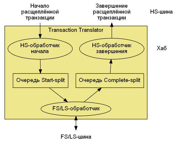
Splitting details are somewhat different for periodic transactions (interrupt transfers and isochronous transfers) and non-periodic (control transfers and data transfers). The figure above shows a diagram of what is happening inside the hub for periodic split transactions. The good news is that for non-periodic transactions the additional support actions are minimal - you need to correctly initialize the channel structure and clear the hub buffer with data when the HS bus fails, the controller itself will follow the rest. For periodic transactions everything is more complicated. This is where the second bitmask arises in the structure of the interrupt channel, which I mentioned earlier - for the FS / LS device interrupt channels, the first bitmask is responsible for the microframes into which the initial split transaction should be initiated, the second for the microframes into which the end split transaction From here, the second type of isochronous transactions appears in EHCI - the structures of ordinary and split isochronous transactions differ.
EHCI and companions
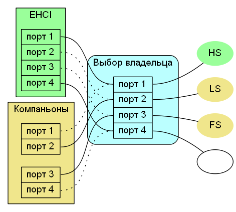
When designing a host controller for USB2, Intel decided to use, if possible, an existing base in the form of UHCI / OHCI hardware and software support. There is no Transaction Translator in the root hub of the EHCI; instead, each port can be connected to a companion controller, it can be UHCI or OHCI. There may be several companions. While the EHCI controller is not initialized, all ports are connected to companions; code that can program UHCI and OHCI will be able to work with all devices and in this configuration, of course, at USB1 speed. After initializing the EHCI controller, each port can be assigned an owner independently of the others. A non-owner controller perceives a port in the "no device" state. Ports on which there really is no device, as well as ports with HS devices are assigned to the EHCI controller; ports with low-speed devices are assigned to a companion controller.
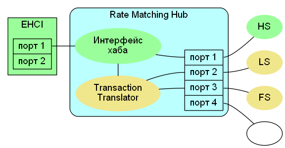
Later, Intel decided that it no longer wants to put UHCI next to the EHCI. In order not to overhaul the specification and not force everyone to rewrite the drivers, Intel did not change the controller, but on the way from the “real” ports to the controller, set up a “virtual” hub with the official name Rate Matching Hub (RMH) , and left the controller only two ports, one of which is always connected to the hub. The purpose of the second port, unfortunately, I could not figure out. From a programmatic point of view, a “virtual” hub is no different from the usual one; just when writing your implementation you should keep in mind that to access devices in some configurations you have to implement not only EHCI support, but also support for hubs.
All articles of the series
Part 1: general scheme
Part 2: Basics of working with host controllers
Part 3: Host Controller Support Code
Part 4: Channel Support Level
Part 5: logic level
Part 6: hub driver
Source: https://habr.com/ru/post/183184/
All Articles