Electricity Lessons - Transmission Lines
Before you start reading the article, try to think about the question: will the current run if you connect a very long wire to the battery (more than 300 thousand kilometers, a superconductor), if the opposite ends of the wire are not connected? How many Amperes?
After reading this article, you will understand what is the meaning of wave resistance. From the lectures on the theory of waves, I only learned that the characteristic impedance is resistance to the waves. Most students seem to understand exactly the same thing. That is nothing.
This article is a very loose translation of this book: Lessons In Electric Circuits
Articles on the topic: On Habré: Contact is, there is no signal
Washipedia Trash: The Long Line
')
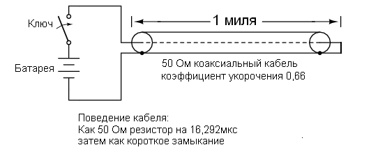
At the beginning of my electronics hobby, I often heard about the 50 Ω coaxial cable characteristic impedance. Coaxial cable is two wires. Central wire, insulator, braid, insulator. Braid completely covers the center conductor. This wire is used to transmit weak signals, and the braid protects the signal from interference.

I was puzzled by this inscription - 50 Ω. How can two insulated conductors have 50 Ω resistance with each other? I measured the resistance between the wires and saw, as expected, a break. Cable resistance from one side to the other is zero. No matter how I connected an ohmmeter, I could not get a resistance of 50 ohms.
What I didn’t understand at the time was how the cable responds to pulses. Of course, the ohmmeter works with direct current, and shows that the conductors are not connected to each other. However, the cable, due to the effect of capacitance and inductance distributed over the entire length, works like a resistor. And just as in a normal resistor, the current is proportional to the voltage. What we see as a pair of conductors is an important element of the circuit in the presence of high-frequency signals.
In this article, you will learn what a communication line is. Many of the effects of communication lines do not appear when working with direct current or at a network frequency of 50 Hz. However, in high-frequency circuits, these effects are quite significant. Practical use of transmission lines - in radio communications, in computer networks, and in low-frequency circuits for protection against voltage surges or lightning strikes.
Consider the following scheme. The circuit is closed - the lamp lights up. The circuit is open - the lamp goes out. In fact, the lamp does not light up instantly. She should at least get hot. But I want to focus not on that. Although electrons move very slowly, they interact with each other much faster — at the speed of light.

What happens if the length of the wires is 300 thousand km? Since electricity is transmitted at a finite speed, very long wires will delay.
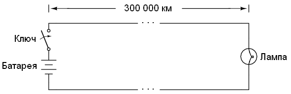
Neglecting time to warm up the lamp, and the resistance of the wires, the lamp will light about 1 second after turning on the switch. Despite the fact that the construction of superconducting transmission lines of such length will create enormous practical problems, this is theoretically possible, therefore our thought experiment is real. When the switch is turned off, the lamp will continue to receive power for another 1 second.
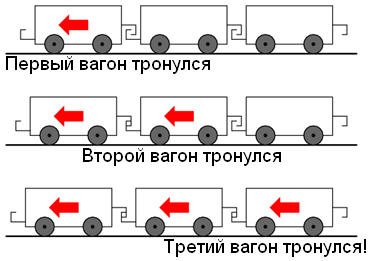
One of the ways to represent the movement of electrons in a conductor is the train cars. The cars themselves move slowly, only start moving, and the coupling wave is transmitted much faster.
Another analogy, perhaps more appropriate, is waves in water. The object begins to move horizontally along the surface. A wave will be created due to the interaction of water molecules. The wave will travel much faster than water molecules move.
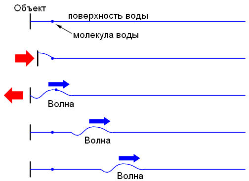
The electrons interact with the speed of light, but move much slower, like the water molecule in the figure above. With a very long circuit, the delay between pressing the switch and turning on the lamp becomes noticeable.
Suppose we have two parallel wires of infinite length, without a bulb at the end. Will the current flow when the circuit breaker is closed?
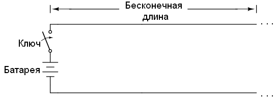
Despite the fact that our wire is a superconductor, we cannot neglect the capacity between the wires:
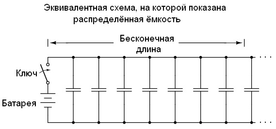
Connect the power to the wire. The charge current of a capacitor is determined by the formula: I = C (de / dt). Accordingly, an instantaneous voltage increase should generate an infinite current.
However, the current cannot be infinite, because along the wires there is an inductance that limits the growth of the current. The voltage drop in the inductance obeys the formula: E = L (dI / dt). This voltage drop limits the maximum current.
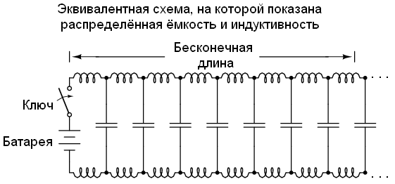
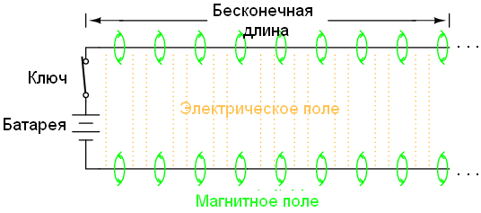
As the electrons interact with the speed of light, the wave will propagate at the same speed. Thus, the current increase in inductances, and the process of charging capacitors will look like this:

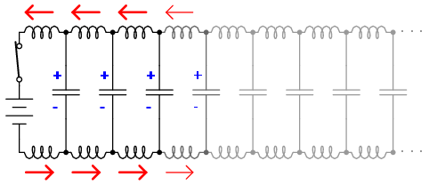
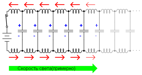
As a result of these interactions, the current through the battery will be limited. Since the wires are infinite, the distributed capacitance will never charge, and the inductance will not allow the current to increase infinitely. In other words, the wires will behave like a constant load.
The transmission line behaves like a constant load in the same way as a resistor. For a power source, there is no difference where current flows: into a resistor, or into a transmission line. Impedance (resistance) This line is called the wave resistance, and it is determined only by the geometry of the conductors. For parallel wires with air insulation, the characteristic impedance is calculated as:

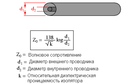
For a coaxial wire, the formula for calculating the impedance looks somewhat different:
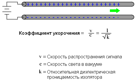
If the insulation material is not a vacuum, the speed of propagation will be less than the speed of light. The ratio of the actual speed to the speed of light is called the coefficient of shortening.
The shortening factor depends only on the properties of the insulator, and is calculated by the following formula:
The characteristic impedance is also known as the characteristic impedance.
From the formula it is clear that the characteristic impedance increases as the distance between the conductors increases. If the conductors are separated from each other, their capacity becomes less, and the distributed inductance increases (the effect of neutralizing two opposite currents is less). Less capacity, more inductance => less current => more resistance. Conversely, the convergence of the wires leads to greater capacity, less inductance => more current => less characteristic impedance.
Eliminating the effects of leakage current through a dielectric, the characteristic impedance is subject to the following formula:

Lines of infinite length are an interesting abstraction, but they are impossible. All lines have a finite length. If that piece of 50 Ohm RG-58 / U cable, which I measured with an ohmmeter a few years ago, was of infinite length, I would record a 50 Ohm resistance between the inner and outer wires. But this line was not infinite, and it was measured as open, with infinite resistance.
However, the characteristic impedance is also important when working with a wire of limited length. If a transient voltage is applied to the line, a current flows that is equal to the ratio of the voltage to the characteristic impedance. This is just Ohm’s law. But he will act not infinitely, but for a limited time.
If there is a break at the end of the line, then the current will be stopped at this point. And this abrupt cessation of current will affect the entire line. Imagine a train going down the rails with slack in the sleeves. If he bumps into a wall, he will not stop all at once: first the first, then the second car, etc.

The signal propagating from the source is called the incident wave. The propagation of the signal from the load back to the source is called the reflected wave.
As soon as the accumulation of electrons at the end of the line spreads back to the battery, the current in the line stops, and it behaves like a normal open circuit. All this happens very quickly for lines of reasonable length so that the ohmmeter does not have time to measure the resistance. It does not have time to catch that period of time when the circuit behaves like a resistor. For a kilometer cable with a shortening factor of 0.66, the signal propagates only 5.05µs. The reflected wave goes back to the source as many more, that is, in the sum of 10.1 μs.
High-speed instruments can measure this time between sending a signal and the arrival of a reflection to determine the length of the cable. This method can also be used to determine the breakage of one or both wires of a cable. Such devices are called reflectometers for cable lines. The basic principle is the same as that of ultrasonic sonars: pulse generation and time measurement until echo.
A similar phenomenon occurs in the event of a short circuit: when a wave reaches the end of the line, it is reflected back, since the voltage cannot exist between two connected wires. When the reflected wave reaches the source, the source sees that a short circuit has occurred. All this happens during the propagation of the signal there + time back.
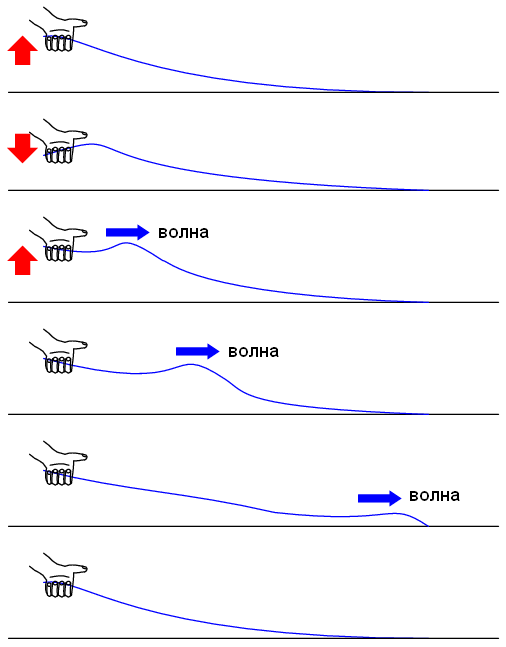
A simple experiment illustrates the phenomenon of wave reflection. Take the rope as shown in the picture and pull it. A wave will begin to spread until it is completely extinguished due to friction.
It looks like a long lossy line. The signal level will drop as you move along the line. However, if the second end is fixed on a solid wall, a reflected wave will appear:
As a rule, the destination of a transmission line is the transmission of an electrical signal from one point to another.
Reflections can be eliminated if the terminator on the line is exactly equal to the characteristic impedance. For example, an open or short-circuited line will reflect the entire signal back to the source. But if a 50 Ohm resistor is turned on at the end of the line, then all the energy will be absorbed on the resistor.
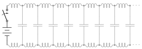
This all makes sense if we return to our hypothetical infinite line. It behaves like a constant resistor. If we limit the length of the wire, then it will behave as a resistor only for a while, and then - as a short circuit, or an open circuit. However, if we put a 50 ohm resistor at the end of the line, it will again behave like an endless line.


In essence, the resistor at the end of the line, equal to the characteristic impedance, makes the line infinite from the point of view of the source, because the resistor can dissipate energy forever just as infinite lines can absorb energy.
The reflected wave, returning back to the source, can again be reflected if the characteristic impedance of the source is not exactly equal to the characteristic impedance. This type of reflection is especially dangerous, it pretends that the source has transmitted impulse.
In DC circuits, the characteristic impedance is usually ignored. Even coaxial cable in such circuits is used only to protect against interference. This is due to short periods of propagation compared with the period of the signal. As we learned in the previous chapter, the transmission line behaves as a resistor until the reflected wave returns to the source. After this time (10.1 µs for the kilometer cable), the source sees the circuit impedance.
If the circuit transmits a low-frequency signal, the source for some time sees the wave resistance, and then the line impedance. We know that the magnitude of the signal is not equal along the entire length of the line due to the propagation at the speed of light (almost). But the phase of the low-frequency signal changes only slightly during the propagation time of the signal. So, we can assume that the voltage and the phase of the signal at all points of the line are equal.
In this case, we can assume that the line is short, because the propagation time is much less than the signal period. In contrast, a long line is one where, during propagation, the waveform has time to change into most of the phase, or even transmit several signal periods. Long lines are considered such when the phase of the signal changes by more than 90 degrees during the propagation time. Prior to this, in this book we considered only short lines.
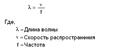
To determine the type of line (long, short), we must compare its length and signal frequency. For example, the period of a signal with a frequency of 60 Hz is equal to 16.66 ms. When propagating at the speed of light (300 thousand km / s), the signal will travel 5000 km. If the shortening coefficient is less than 1, then the speed will be less than 300 thousand km / s, and the distance is less by the same time. But even if you use the coefficient of shortening the coaxial cable (0.66), the distance will still be great - 3300km! Regardless of cable length, this is called wavelength.
A simple formula allows you to calculate the wavelength:
A long line is one where at least ¼ of the wavelength is in length. And now you can understand why all the lines before are short. For 60Hz AC power systems, the cable length must exceed 825 km in order for the signal propagation effects to become significant. Cables from the audio amplifier to the speakers must be more than 7.5 km in length to significantly affect the 10 kHz beep!
When dealing with radio frequency systems, the problem with the length of the transmission line is far from being so trivial. Consider a 100 MHz radio signal: its wavelength is 3 meters, even at the speed of light. The transmission line must be more than 75 cm in length to be considered long. With a shortening coefficient of 0.66, this critical length will be only 50 cm.
When an electrical source is connected to the load via a short transmission line, the load impedance dominates. That is, when the line is short, the characteristic impedance does not affect the behavior of the circuit. We can see this when testing coaxial cable with an ohmmeter: we see a gap. Although the line behaves like a 50Ohm resistor (RG / 58U cable) for a short time, after this time we will see a break. Since the reaction time of an ohmmeter is much longer than the signal propagation time, we see a break. This very high signal propagation speed does not allow us to detect a 50 Ohm contact resistance with an ohmmeter.
If we use a coaxial cable for transmitting direct current, the cable will be considered short, and its characteristic impedance will not affect the operation of the circuit. Please note that a short line will be called any line where the change in signal is slower than the signal propagates along the line. Almost any physical cable length can be short in terms of wave resistance and reflected waves. Using the same cable to transmit a high-frequency signal, you can estimate the length of the line in different ways.
If the source is connected to the load via long transmission lines, the characteristic impedance dominates the load impedance. In other words, the electrically long line acts as the main component in the circuit, and its properties dominate the properties of the load. With the source connected to one end of the cable and transmits the current to the load, but the current primarily goes not to the load, but to the line. This is becoming more true, the longer the line. Consider our hypothetical 50Ω endless cable. No matter what kind of load we connect to the other end, the source will only see 50 ohms. In this case, the line resistance is decisive, and the load resistance will not matter.
The most effective way to minimize the influence of the length of the transmission line is to load the line with resistance. If the load impedance is equal to the characteristic impedance, then any source will see the same impedance, regardless of the line length. Thus, the line length will only affect the signal delay. However, the complete coincidence of the load resistance and wave resistance is not always possible.
The next section deals with transmission lines, especially when the line length is equal to the fractional part of the wave.
I hope you have clarified the basic physical principles of cable operation.
Unfortunately, the next chapter is very big. The book is read in one breath, and at some point you need to stop. For the first post, I think that's enough. Thanks for attention.
Continuation here
After reading this article, you will understand what is the meaning of wave resistance. From the lectures on the theory of waves, I only learned that the characteristic impedance is resistance to the waves. Most students seem to understand exactly the same thing. That is nothing.
This article is a very loose translation of this book: Lessons In Electric Circuits
Articles on the topic: On Habré: Contact is, there is no signal
Washipedia Trash: The Long Line
')
50 ohm cable?
At the beginning of my electronics hobby, I often heard about the 50 Ω coaxial cable characteristic impedance. Coaxial cable is two wires. Central wire, insulator, braid, insulator. Braid completely covers the center conductor. This wire is used to transmit weak signals, and the braid protects the signal from interference.
I was puzzled by this inscription - 50 Ω. How can two insulated conductors have 50 Ω resistance with each other? I measured the resistance between the wires and saw, as expected, a break. Cable resistance from one side to the other is zero. No matter how I connected an ohmmeter, I could not get a resistance of 50 ohms.
What I didn’t understand at the time was how the cable responds to pulses. Of course, the ohmmeter works with direct current, and shows that the conductors are not connected to each other. However, the cable, due to the effect of capacitance and inductance distributed over the entire length, works like a resistor. And just as in a normal resistor, the current is proportional to the voltage. What we see as a pair of conductors is an important element of the circuit in the presence of high-frequency signals.
In this article, you will learn what a communication line is. Many of the effects of communication lines do not appear when working with direct current or at a network frequency of 50 Hz. However, in high-frequency circuits, these effects are quite significant. Practical use of transmission lines - in radio communications, in computer networks, and in low-frequency circuits for protection against voltage surges or lightning strikes.
Wires and speed of light
Consider the following scheme. The circuit is closed - the lamp lights up. The circuit is open - the lamp goes out. In fact, the lamp does not light up instantly. She should at least get hot. But I want to focus not on that. Although electrons move very slowly, they interact with each other much faster — at the speed of light.
What happens if the length of the wires is 300 thousand km? Since electricity is transmitted at a finite speed, very long wires will delay.
Neglecting time to warm up the lamp, and the resistance of the wires, the lamp will light about 1 second after turning on the switch. Despite the fact that the construction of superconducting transmission lines of such length will create enormous practical problems, this is theoretically possible, therefore our thought experiment is real. When the switch is turned off, the lamp will continue to receive power for another 1 second.
One of the ways to represent the movement of electrons in a conductor is the train cars. The cars themselves move slowly, only start moving, and the coupling wave is transmitted much faster.
Another analogy, perhaps more appropriate, is waves in water. The object begins to move horizontally along the surface. A wave will be created due to the interaction of water molecules. The wave will travel much faster than water molecules move.
The electrons interact with the speed of light, but move much slower, like the water molecule in the figure above. With a very long circuit, the delay between pressing the switch and turning on the lamp becomes noticeable.
Wave resistance
Suppose we have two parallel wires of infinite length, without a bulb at the end. Will the current flow when the circuit breaker is closed?
Despite the fact that our wire is a superconductor, we cannot neglect the capacity between the wires:
Connect the power to the wire. The charge current of a capacitor is determined by the formula: I = C (de / dt). Accordingly, an instantaneous voltage increase should generate an infinite current.
However, the current cannot be infinite, because along the wires there is an inductance that limits the growth of the current. The voltage drop in the inductance obeys the formula: E = L (dI / dt). This voltage drop limits the maximum current.
As the electrons interact with the speed of light, the wave will propagate at the same speed. Thus, the current increase in inductances, and the process of charging capacitors will look like this:
As a result of these interactions, the current through the battery will be limited. Since the wires are infinite, the distributed capacitance will never charge, and the inductance will not allow the current to increase infinitely. In other words, the wires will behave like a constant load.
The transmission line behaves like a constant load in the same way as a resistor. For a power source, there is no difference where current flows: into a resistor, or into a transmission line. Impedance (resistance) This line is called the wave resistance, and it is determined only by the geometry of the conductors. For parallel wires with air insulation, the characteristic impedance is calculated as:
For a coaxial wire, the formula for calculating the impedance looks somewhat different:
If the insulation material is not a vacuum, the speed of propagation will be less than the speed of light. The ratio of the actual speed to the speed of light is called the coefficient of shortening.
The shortening factor depends only on the properties of the insulator, and is calculated by the following formula:
The characteristic impedance is also known as the characteristic impedance.
From the formula it is clear that the characteristic impedance increases as the distance between the conductors increases. If the conductors are separated from each other, their capacity becomes less, and the distributed inductance increases (the effect of neutralizing two opposite currents is less). Less capacity, more inductance => less current => more resistance. Conversely, the convergence of the wires leads to greater capacity, less inductance => more current => less characteristic impedance.
Eliminating the effects of leakage current through a dielectric, the characteristic impedance is subject to the following formula:
Finite Length Transmission Lines
Lines of infinite length are an interesting abstraction, but they are impossible. All lines have a finite length. If that piece of 50 Ohm RG-58 / U cable, which I measured with an ohmmeter a few years ago, was of infinite length, I would record a 50 Ohm resistance between the inner and outer wires. But this line was not infinite, and it was measured as open, with infinite resistance.
However, the characteristic impedance is also important when working with a wire of limited length. If a transient voltage is applied to the line, a current flows that is equal to the ratio of the voltage to the characteristic impedance. This is just Ohm’s law. But he will act not infinitely, but for a limited time.
If there is a break at the end of the line, then the current will be stopped at this point. And this abrupt cessation of current will affect the entire line. Imagine a train going down the rails with slack in the sleeves. If he bumps into a wall, he will not stop all at once: first the first, then the second car, etc.
The signal propagating from the source is called the incident wave. The propagation of the signal from the load back to the source is called the reflected wave.
As soon as the accumulation of electrons at the end of the line spreads back to the battery, the current in the line stops, and it behaves like a normal open circuit. All this happens very quickly for lines of reasonable length so that the ohmmeter does not have time to measure the resistance. It does not have time to catch that period of time when the circuit behaves like a resistor. For a kilometer cable with a shortening factor of 0.66, the signal propagates only 5.05µs. The reflected wave goes back to the source as many more, that is, in the sum of 10.1 μs.
High-speed instruments can measure this time between sending a signal and the arrival of a reflection to determine the length of the cable. This method can also be used to determine the breakage of one or both wires of a cable. Such devices are called reflectometers for cable lines. The basic principle is the same as that of ultrasonic sonars: pulse generation and time measurement until echo.
A similar phenomenon occurs in the event of a short circuit: when a wave reaches the end of the line, it is reflected back, since the voltage cannot exist between two connected wires. When the reflected wave reaches the source, the source sees that a short circuit has occurred. All this happens during the propagation of the signal there + time back.
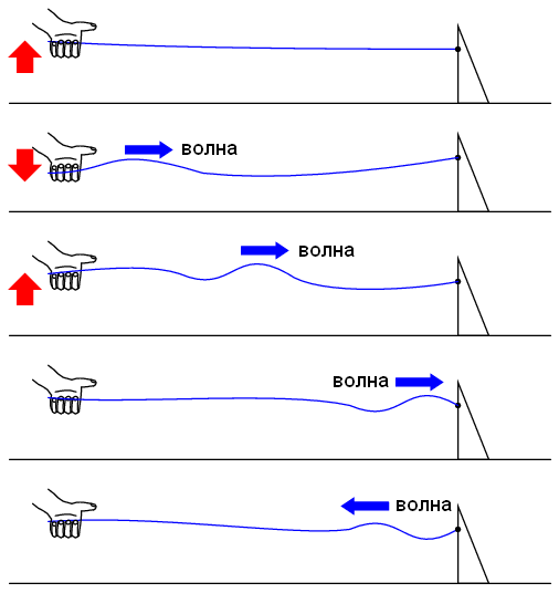
A simple experiment illustrates the phenomenon of wave reflection. Take the rope as shown in the picture and pull it. A wave will begin to spread until it is completely extinguished due to friction.
It looks like a long lossy line. The signal level will drop as you move along the line. However, if the second end is fixed on a solid wall, a reflected wave will appear:
As a rule, the destination of a transmission line is the transmission of an electrical signal from one point to another.
Reflections can be eliminated if the terminator on the line is exactly equal to the characteristic impedance. For example, an open or short-circuited line will reflect the entire signal back to the source. But if a 50 Ohm resistor is turned on at the end of the line, then all the energy will be absorbed on the resistor.
This all makes sense if we return to our hypothetical infinite line. It behaves like a constant resistor. If we limit the length of the wire, then it will behave as a resistor only for a while, and then - as a short circuit, or an open circuit. However, if we put a 50 ohm resistor at the end of the line, it will again behave like an endless line.
In essence, the resistor at the end of the line, equal to the characteristic impedance, makes the line infinite from the point of view of the source, because the resistor can dissipate energy forever just as infinite lines can absorb energy.
The reflected wave, returning back to the source, can again be reflected if the characteristic impedance of the source is not exactly equal to the characteristic impedance. This type of reflection is especially dangerous, it pretends that the source has transmitted impulse.
Short and long transmission lines
In DC circuits, the characteristic impedance is usually ignored. Even coaxial cable in such circuits is used only to protect against interference. This is due to short periods of propagation compared with the period of the signal. As we learned in the previous chapter, the transmission line behaves as a resistor until the reflected wave returns to the source. After this time (10.1 µs for the kilometer cable), the source sees the circuit impedance.
If the circuit transmits a low-frequency signal, the source for some time sees the wave resistance, and then the line impedance. We know that the magnitude of the signal is not equal along the entire length of the line due to the propagation at the speed of light (almost). But the phase of the low-frequency signal changes only slightly during the propagation time of the signal. So, we can assume that the voltage and the phase of the signal at all points of the line are equal.
In this case, we can assume that the line is short, because the propagation time is much less than the signal period. In contrast, a long line is one where, during propagation, the waveform has time to change into most of the phase, or even transmit several signal periods. Long lines are considered such when the phase of the signal changes by more than 90 degrees during the propagation time. Prior to this, in this book we considered only short lines.
To determine the type of line (long, short), we must compare its length and signal frequency. For example, the period of a signal with a frequency of 60 Hz is equal to 16.66 ms. When propagating at the speed of light (300 thousand km / s), the signal will travel 5000 km. If the shortening coefficient is less than 1, then the speed will be less than 300 thousand km / s, and the distance is less by the same time. But even if you use the coefficient of shortening the coaxial cable (0.66), the distance will still be great - 3300km! Regardless of cable length, this is called wavelength.
A simple formula allows you to calculate the wavelength:
A long line is one where at least ¼ of the wavelength is in length. And now you can understand why all the lines before are short. For 60Hz AC power systems, the cable length must exceed 825 km in order for the signal propagation effects to become significant. Cables from the audio amplifier to the speakers must be more than 7.5 km in length to significantly affect the 10 kHz beep!
When dealing with radio frequency systems, the problem with the length of the transmission line is far from being so trivial. Consider a 100 MHz radio signal: its wavelength is 3 meters, even at the speed of light. The transmission line must be more than 75 cm in length to be considered long. With a shortening coefficient of 0.66, this critical length will be only 50 cm.
When an electrical source is connected to the load via a short transmission line, the load impedance dominates. That is, when the line is short, the characteristic impedance does not affect the behavior of the circuit. We can see this when testing coaxial cable with an ohmmeter: we see a gap. Although the line behaves like a 50Ohm resistor (RG / 58U cable) for a short time, after this time we will see a break. Since the reaction time of an ohmmeter is much longer than the signal propagation time, we see a break. This very high signal propagation speed does not allow us to detect a 50 Ohm contact resistance with an ohmmeter.
If we use a coaxial cable for transmitting direct current, the cable will be considered short, and its characteristic impedance will not affect the operation of the circuit. Please note that a short line will be called any line where the change in signal is slower than the signal propagates along the line. Almost any physical cable length can be short in terms of wave resistance and reflected waves. Using the same cable to transmit a high-frequency signal, you can estimate the length of the line in different ways.
If the source is connected to the load via long transmission lines, the characteristic impedance dominates the load impedance. In other words, the electrically long line acts as the main component in the circuit, and its properties dominate the properties of the load. With the source connected to one end of the cable and transmits the current to the load, but the current primarily goes not to the load, but to the line. This is becoming more true, the longer the line. Consider our hypothetical 50Ω endless cable. No matter what kind of load we connect to the other end, the source will only see 50 ohms. In this case, the line resistance is decisive, and the load resistance will not matter.
The most effective way to minimize the influence of the length of the transmission line is to load the line with resistance. If the load impedance is equal to the characteristic impedance, then any source will see the same impedance, regardless of the line length. Thus, the line length will only affect the signal delay. However, the complete coincidence of the load resistance and wave resistance is not always possible.
The next section deals with transmission lines, especially when the line length is equal to the fractional part of the wave.
I hope you have clarified the basic physical principles of cable operation.
Unfortunately, the next chapter is very big. The book is read in one breath, and at some point you need to stop. For the first post, I think that's enough. Thanks for attention.
Continuation here
Source: https://habr.com/ru/post/183006/
All Articles