Universal Remote Control for XBMC from TP Link MR3020
About the home wireless router TP Link MR3020 with Openwrt already written on Habré . In this article I will tell you how to teach this inexpensive but useful box to control a TV, XBMC player and any other home electronics that understand IR signals from the control panel. Moreover, the MR3020 itself will learn to receive signals from any remote control.
What and how specifically to manage it is up to you, who will undertake to repeat the steps described below. I have such boxes now manage a bunch of TV-XBMC in the living room and in the kitchen. At the same time, only one remote control is used for control. In the near future - to choose in the next underground passage a console that will appeal to all households, and to purchase such items 3. Of course, the same farm can be controlled from an Android tablet (via Wi-Fi) or from a computer (via Ethernet), but this way it seems that no one in my family inspires me.
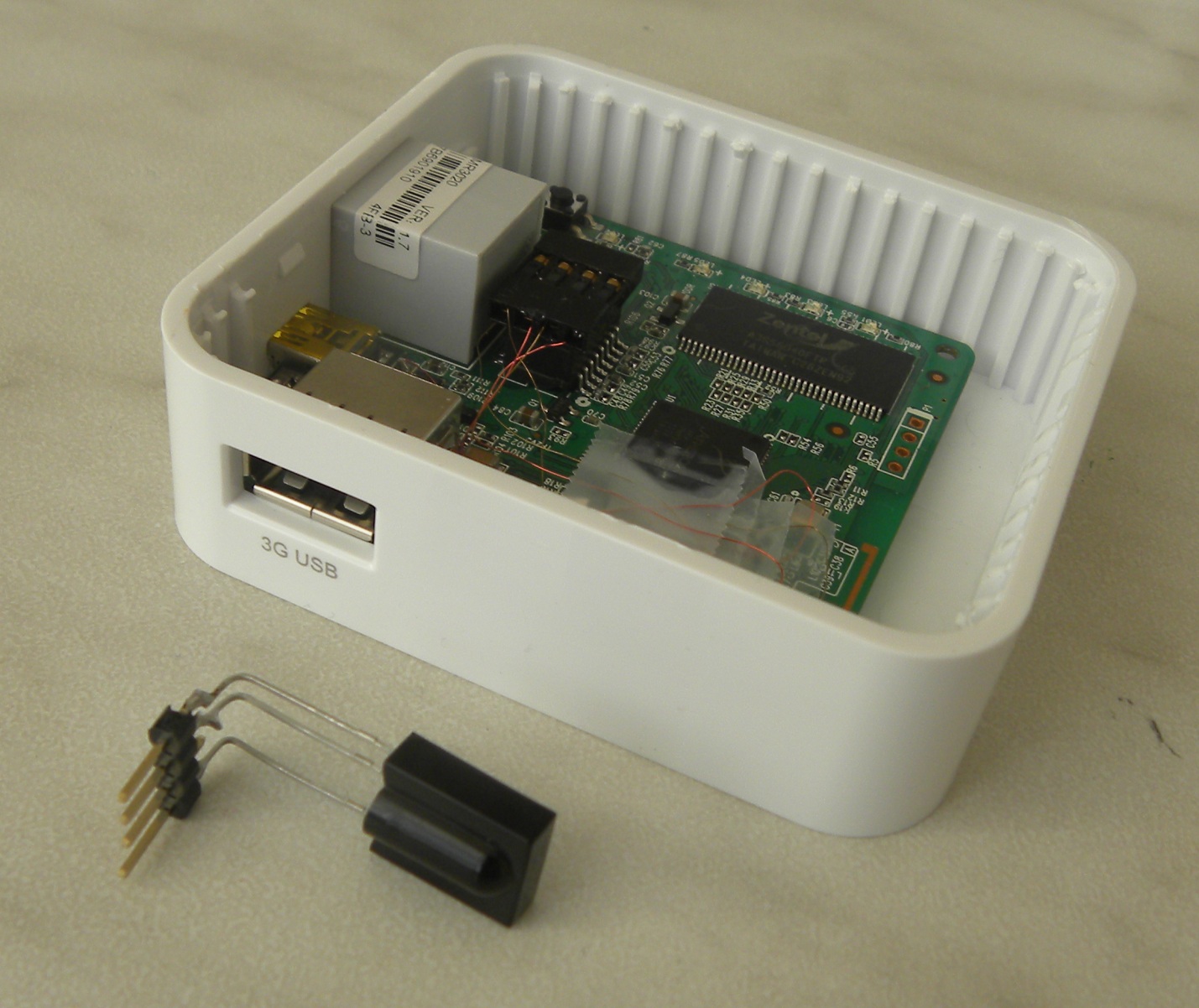
The soldered box and its accessories look like this to me:

')
In the center is a converted device. The pins of the mini-USB connector are used to connect a pair of photodetector-LED. These components are placed in the case from under a cheap Dialog microphone (native slide from the microphone is then attached to the velcro on the TV, near the native television IR receiver). For power, a new connector (normal, 2-pin) is removed.
Here's how all this strapping looks on TV:
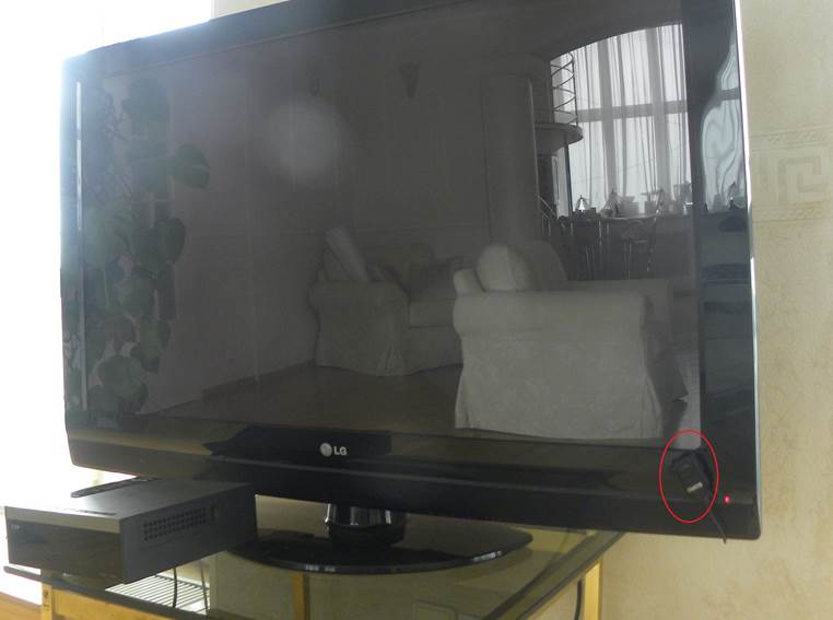
In the red circle is visible connected receiver-emitter.
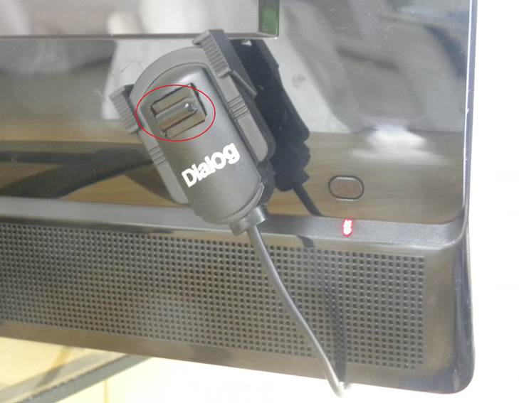
But he is near (in the circle - IR photodetector):
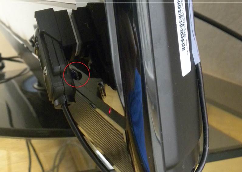
The back part of the device shines in the IR receiver of the TV (the circle is circled IR LED):
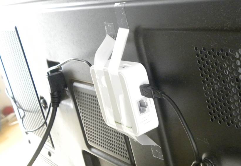
An adhesive tape router is attached to the back of the TV (be sure to choose a place that does not heat up on the TV). A little not aesthetically pleasing, but who is looking there?
Perhaps in your case, everything will look neater and prettier. But the approximate sequence of steps for assembly, I think, will be the same.
The first step is to familiarize yourself with the page about the Openwrt router . On the page there is an instruction for disassembling the device . We open the box and look for somewhere to solder.
Actually, where to solder another useful link will tell - a page in French about using GPIO 7 and 29 for i2c bus . Actually, we will use the same GPIO for connecting the IR receiver (GPIO 7) and the LED (GPIO 29). Our goal is to connect to exactly the same places as in the article (R15, R17, 5 V, land). One important detail: unlike the article, it is not necessary to unsolder the resistors R15 and R17 . So it takes much less effort, and the risk of damaging the contact tracks is minimal.
So, the second step - solder. The choice of wires for soldering is a very important matter. I used single core hairs from broken headphones. The tip of this wiring is easily tinned (heating leads to destruction of the insulation at the tip), and soldering the tinned wiring is quite simple. One piece of advice: before soldering, fix the wiring to the board with scotch tape, gently pull the wiring to the desired length, and with a toothpick, place the tip of the wiring exactly on the contact pad. Thus, the posting will be accurately fixed in its place, and soldering is reduced to a short touch of the soldering iron with a needle to the point of contact.
I recommend TSOP31238 as a receiver, and a TSAL5100 photodiode as a radiator (I took it in St. Petersburg, in “Chip and Dip” together with connectors).
Connection diagram looks like this:
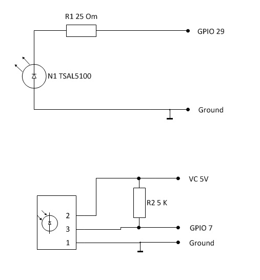
Resistor R2 (5 K) is needed in order not to solder the built-in resistor R15.
During debugging, the easiest way is to bring the necessary wiring (5 V, ground, GPIO 7, GPIO 29) to a 4-pin mother-pad, and to glue the mother herself with superglue to a suitable T1 chip (Ethernet amplifier circuits). It looks like this:
And with a connected photoreceiver - like this:

As you can see, the contact block is quite securely fixed on the board, the wiring-hairs near the contacts are fixed with scotch tape, and thus all elements of the system do not hang out and provide both reliable connection of internal elements and connection of external (IR sensor, IR receiver) as needed. So, let's say all wiring is soldered, and the LED with the photo-receiver is connected according to the diagrams.
I will not describe in detail lirc and go into the modifications for this project (those who wish can get the source code on githab). In short, this is at the heart of the lirc 0.9.0 project, but its serial driver has been slightly reworked to manage the GPIO.
We are flashing the device with the final Openwrt Attitude Adjustment firmware. The firmware is quite simple and the whole process is beautifully described, for example, here . It will be necessary to configure the router in such a way as to ensure connection to the network. The easiest way to configure is to use the built-in web interface.
The following describes the steps to install the necessary programs from a Windows computer. First of all, you need to install putty on our work computer.
Download the following files to the directory with the putty installed: lirc_0.9.0-1_ar71xx.ipk and lirctools_0.9.0-1_ar71xx.ipk
Now copy these files to the MR3020 using the following commands (replace 192.168.1.1 with the address of your router):
We go to the device using putty (ssh). We type the following commands:
Now try running lirc manually:
Try to light up any IR remote control in the IR photodetector window. If the device reacts, then lirc is ready to work as a photodetector. Press Ctrl-C and proceed to the next part.
Create a file /etc/init.d/lirc as follows:
Allow lirc execution:
Reboot the router.
First of all, you need to download or generate the lircd.conf file itself. This file contains the remote control codes for a specific device (TV, DVD, etc.). There is a chance that your console has already been digitized by someone, and the necessary file can be found on the lirc website. Suppose that the desired distance from LG is called AKB33871420. Upload its file to your home directory:
If your remote is not on the site, it's time to write it down. Prepare to press all the buttons on your remote control and launch it in putty (do not forget to change MYREMOTE to the name of your remote control, for example AKB33871420):
Next, carefully follow the instructions and write the file MYREMOTE with the codes of our remote control.
So, in the home directory there was a file for our remote control. Copy it to the lirc folder.
Once again we will light our remote control to the receiver. We carefully watch how irw responds. If everything is in order, our codes began to be recognized. Played enough? Press Ctrl-C to exit and move on. Let's try to light on the TV with our device. We direct the photodiode in the direction of the TV and give the following command:
Here MYREMOTE is the name of the remote control, and mute is the code for the mute key. The names of both parameters can be specified in the lircd.conf file.
If everything goes well, the TV will respond to the mute command. In this case, congratulations to each other - everything worked. It remains only to configure the device to automatically download the necessary components at the start (the notorious “final touch”).
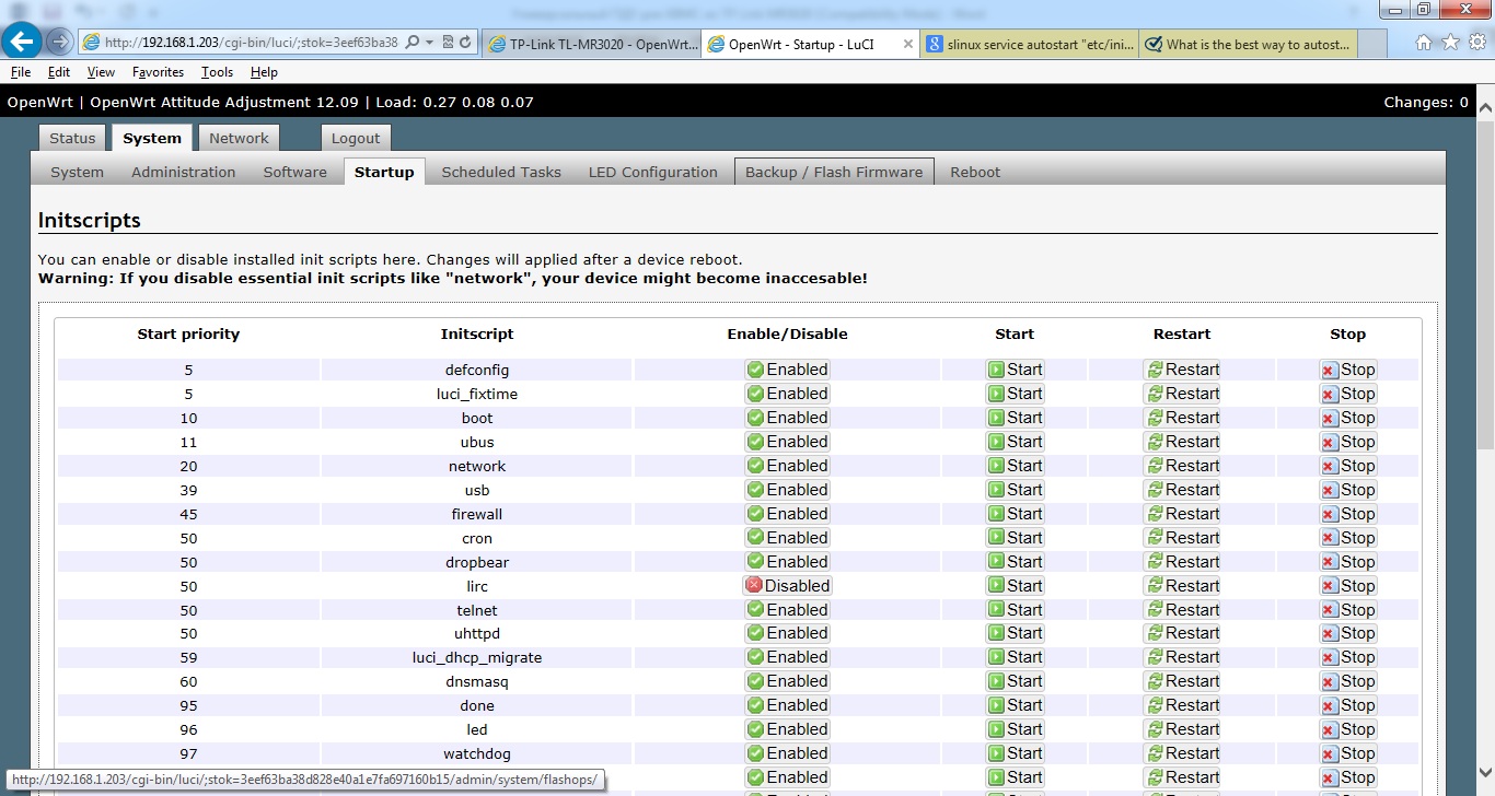
In the openwrt administrative interface, we change the lirc status from “disabled” to “ enabled ”. Now lirc will start automatically when the router boots.
The box is ready to go! Now your TP-Link MR3020 can receive and transmit IR signals.
It remains only to study irexec and create the appropriate /root/.lircrc file - and now your TV can already understand the non-native console.
If you noticed, our lircd already accepts remote convections on the standard port 8765. This will simplify the configuration of the xbmc + lirc bundle on the linux media player. If xbmc runs on Windows, we dig towards eventghost + xbmc
As a result, we get the ability to reprogram the behavior of the remote control for specific home needs, as well as the ability to control home electronics via the web (since the resulting box can receive commands not only via IR, but also via the usual WiFi / Enternet interface.
In general, and sundry, a soldering iron in hand and - go ahead!
What and how specifically to manage it is up to you, who will undertake to repeat the steps described below. I have such boxes now manage a bunch of TV-XBMC in the living room and in the kitchen. At the same time, only one remote control is used for control. In the near future - to choose in the next underground passage a console that will appeal to all households, and to purchase such items 3. Of course, the same farm can be controlled from an Android tablet (via Wi-Fi) or from a computer (via Ethernet), but this way it seems that no one in my family inspires me.
The soldered box and its accessories look like this to me:
')
In the center is a converted device. The pins of the mini-USB connector are used to connect a pair of photodetector-LED. These components are placed in the case from under a cheap Dialog microphone (native slide from the microphone is then attached to the velcro on the TV, near the native television IR receiver). For power, a new connector (normal, 2-pin) is removed.
Here's how all this strapping looks on TV:
In the red circle is visible connected receiver-emitter.
But he is near (in the circle - IR photodetector):
The back part of the device shines in the IR receiver of the TV (the circle is circled IR LED):
An adhesive tape router is attached to the back of the TV (be sure to choose a place that does not heat up on the TV). A little not aesthetically pleasing, but who is looking there?
Perhaps in your case, everything will look neater and prettier. But the approximate sequence of steps for assembly, I think, will be the same.
So, let's begin…
The first step is to familiarize yourself with the page about the Openwrt router . On the page there is an instruction for disassembling the device . We open the box and look for somewhere to solder.
Actually, where to solder another useful link will tell - a page in French about using GPIO 7 and 29 for i2c bus . Actually, we will use the same GPIO for connecting the IR receiver (GPIO 7) and the LED (GPIO 29). Our goal is to connect to exactly the same places as in the article (R15, R17, 5 V, land). One important detail: unlike the article, it is not necessary to unsolder the resistors R15 and R17 . So it takes much less effort, and the risk of damaging the contact tracks is minimal.
So, the second step - solder. The choice of wires for soldering is a very important matter. I used single core hairs from broken headphones. The tip of this wiring is easily tinned (heating leads to destruction of the insulation at the tip), and soldering the tinned wiring is quite simple. One piece of advice: before soldering, fix the wiring to the board with scotch tape, gently pull the wiring to the desired length, and with a toothpick, place the tip of the wiring exactly on the contact pad. Thus, the posting will be accurately fixed in its place, and soldering is reduced to a short touch of the soldering iron with a needle to the point of contact.
I recommend TSOP31238 as a receiver, and a TSAL5100 photodiode as a radiator (I took it in St. Petersburg, in “Chip and Dip” together with connectors).
Connection diagram looks like this:
Resistor R2 (5 K) is needed in order not to solder the built-in resistor R15.
During debugging, the easiest way is to bring the necessary wiring (5 V, ground, GPIO 7, GPIO 29) to a 4-pin mother-pad, and to glue the mother herself with superglue to a suitable T1 chip (Ethernet amplifier circuits). It looks like this:
And with a connected photoreceiver - like this:
As you can see, the contact block is quite securely fixed on the board, the wiring-hairs near the contacts are fixed with scotch tape, and thus all elements of the system do not hang out and provide both reliable connection of internal elements and connection of external (IR sensor, IR receiver) as needed. So, let's say all wiring is soldered, and the LED with the photo-receiver is connected according to the diagrams.
The last step remains - software.
I will not describe in detail lirc and go into the modifications for this project (those who wish can get the source code on githab). In short, this is at the heart of the lirc 0.9.0 project, but its serial driver has been slightly reworked to manage the GPIO.
We are flashing the device with the final Openwrt Attitude Adjustment firmware. The firmware is quite simple and the whole process is beautifully described, for example, here . It will be necessary to configure the router in such a way as to ensure connection to the network. The easiest way to configure is to use the built-in web interface.
The following describes the steps to install the necessary programs from a Windows computer. First of all, you need to install putty on our work computer.
Download the following files to the directory with the putty installed: lirc_0.9.0-1_ar71xx.ipk and lirctools_0.9.0-1_ar71xx.ipk
Now copy these files to the MR3020 using the following commands (replace 192.168.1.1 with the address of your router):
pscp.exe -scp lirc_0.9.0-1_ar71xx.ipk root@192.168.1.1:.pscp.exe -scp lirctools_0.9.0-1_ar71xx.ipk root@192.168.1.1:.We go to the device using putty (ssh). We type the following commands:
opkg install lirc_0.9.0-1_ar71xx.ipkopkg install lirctools_0.9.0-1_ar71xx.ipkNow try running lirc manually:
insmod lirc_devmkdir -p /var/run/lirclircdinsmod lirc_serial gpio_in_pin=7 gpio_out_pin=29 debug=1mode2 -d /dev/lirc0Try to light up any IR remote control in the IR photodetector window. If the device reacts, then lirc is ready to work as a photodetector. Press Ctrl-C and proceed to the next part.
Create a file /etc/init.d/lirc as follows:
#!/bin/sh /etc/rc.common# Copyright (C) 2006-2011 OpenWrt.orgSTART=50start() {insmod lirc_devmkdir -p /var/run/lircservice_start /usr/sbin/lircd --release=_END --listen=0.0.0.0:8765 --device=/dev/lirc0insmod lirc_serial gpio_in_pin=7 gpio_out_pin=0 debug=1service_start /usr/sbin/irexec -d /root/.lircrc}stop() {killall irexeckillall lircdrmmod lirc_serialrmmod lirc_dev}Allow lirc execution:
chmod +x /etc/init.d/lircReboot the router.
Now check the transmitter performance.
First of all, you need to download or generate the lircd.conf file itself. This file contains the remote control codes for a specific device (TV, DVD, etc.). There is a chance that your console has already been digitized by someone, and the necessary file can be found on the lirc website. Suppose that the desired distance from LG is called AKB33871420. Upload its file to your home directory:
wget lirc.sourceforge.net/remotes/lg/AKB33871420If your remote is not on the site, it's time to write it down. Prepare to press all the buttons on your remote control and launch it in putty (do not forget to change MYREMOTE to the name of your remote control, for example AKB33871420):
/etc/init.d/lirc startKillall lircdirrecord -d /dev/lirc0 -n MYREMOTENext, carefully follow the instructions and write the file MYREMOTE with the codes of our remote control.
So, in the home directory there was a file for our remote control. Copy it to the lirc folder.
cp MYREMOTE /etc/lircd.conf/etc/init.d/lirc stop/etc/init.d/lirc startirwOnce again we will light our remote control to the receiver. We carefully watch how irw responds. If everything is in order, our codes began to be recognized. Played enough? Press Ctrl-C to exit and move on. Let's try to light on the TV with our device. We direct the photodiode in the direction of the TV and give the following command:
irsend send_once MYREMOTE muteHere MYREMOTE is the name of the remote control, and mute is the code for the mute key. The names of both parameters can be specified in the lircd.conf file.
If everything goes well, the TV will respond to the mute command. In this case, congratulations to each other - everything worked. It remains only to configure the device to automatically download the necessary components at the start (the notorious “final touch”).
In the openwrt administrative interface, we change the lirc status from “disabled” to “ enabled ”. Now lirc will start automatically when the router boots.
The box is ready to go! Now your TP-Link MR3020 can receive and transmit IR signals.
It remains only to study irexec and create the appropriate /root/.lircrc file - and now your TV can already understand the non-native console.
If you noticed, our lircd already accepts remote convections on the standard port 8765. This will simplify the configuration of the xbmc + lirc bundle on the linux media player. If xbmc runs on Windows, we dig towards eventghost + xbmc
Conclusion
As a result, we get the ability to reprogram the behavior of the remote control for specific home needs, as well as the ability to control home electronics via the web (since the resulting box can receive commands not only via IR, but also via the usual WiFi / Enternet interface.
In general, and sundry, a soldering iron in hand and - go ahead!
Source: https://habr.com/ru/post/182832/
All Articles