HiRISE or how to photograph Mars from orbit
Encouraged by the success in popularizing Mars exploration for the Russian-speaking audience ( one and two times ), I wanted to read about technical details about how absolutely fantastic pictures are obtained (for example, one and two times ). But search on Habra gave only references to the camera, without any details. Surprisingly surprised, I googled separate descriptions of the device, the principle of operation and the interaction of devices in the MRO (Mars Reconnaissance Orbiter - Martian reconnaissance satellite) in English and a brief compilation of all this in Russian Wikipedia. Considering that the topic of Mars is still (and, probably, always) relevant, I decided for all who are interested to make a more complete description of the high-resolution camera orbiting Mars - HiRISE (High Resolution Imaging Science Experiment).
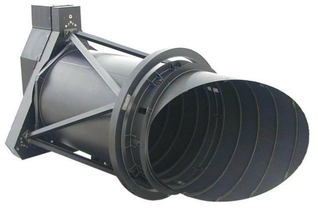
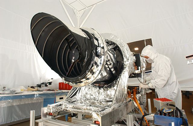
Let's start with the story. Which was born in the late 80s by the efforts of Alan Delamere from Ball Aerospace. Alan began to design a camera that could shoot remote objects with very high resolution. However, in practice, it was not until the 2000s that the University of Arizona began preparing the multi-function automatic interplanetary station MRO (Mars Reconnaissance Orbiter) to translate its ideas. Having united with the scientists of the University in 2001, NASA obtained principal agreement on the installation of such a camera in the MRO and on August 12, 2005 it was successfully installed:
')
I think there is not much point in describing the goals of the mission, the HiRISE journey to Mars, the famous family portrait of the Earth and the Moon , temporary misadventures with equipment, etc., all this can be found in the corresponding article in Wikipedia .
But what is not there is a device HiRISE and features of its equipment.
The main components of HiRISE as a whole roughly correspond to the device of any space telescope: optical system and control electronics :)
But since the camera was required to take pictures of the features of the Martian surface (both already known and not detected earlier) with high resolution and contrast, it had to have not only a wide capture band, but also a very good signal-to-noise ratio. And if we add to this the limitations on mass, budget, project deadlines, and a huge ground speed of flight (3.4 km / s), then the achievement of these shooting parameters is clearly not a trivial task.
The photodetector of the device is an astigmatic reflecting telescope with a system of 3 mirrors. HiRISE uses lightweight Zerodur optics and carbon fiber composite materials. The use of carbon fiber gives a light but stiff frame and low absorption with a low coefficient of swelling. Composite elements with a negative thermal expansion in combination with metal compounds (having a positive coefficient of expansion) avoid the deformation of the structure.
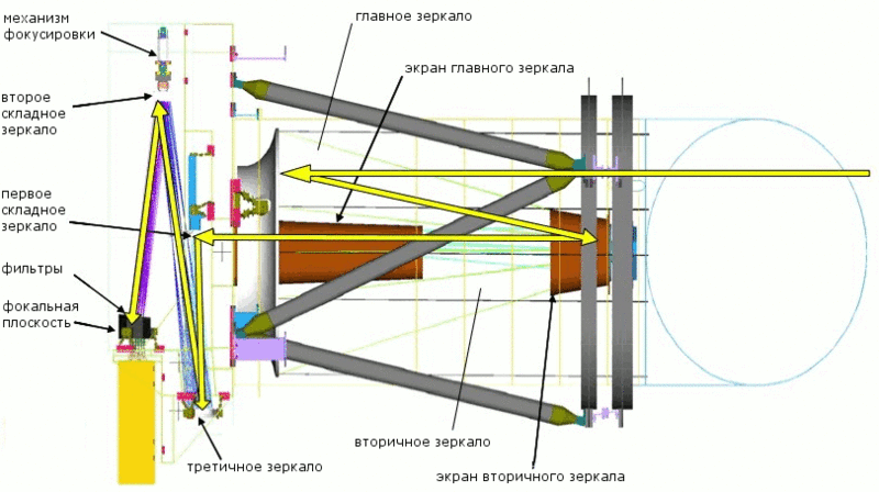
The use of a Cassegrain circuit in the lens (see picture) with wrapping optics and two mirrors was optimized to work at the level of the diffraction limit with a narrow band of coverage, which is obtained when shooting along the motion of the spacecraft (the so-called push-broom shooting, which will be discussed further ). Filters in front of the detectors divide the light flux into 3 spectral ranges: red (panchromatic), blue-green and near-infrared.
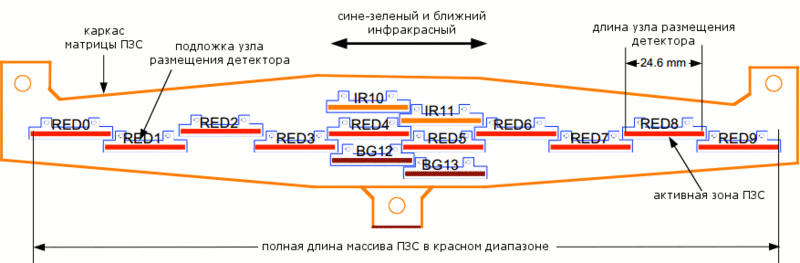
The CCDs are zigzagged to close the entire aisle area, without any gaps. The blue-green and near-infrared ranges each have 2 detectors with a total bandwidth of 4048 px, 10 for the red band there are 10 detectors with a total width of 20264 px.
The 50 cm main mirror has a double-arch design for weight reduction and increased strength. Color filters are located 30 mm from the detectors, which allows to avoid problems due to ambient light and multiple reflections of the quasi-collimated beam. Lyot's stop (Lyot stop), located between the tertiary and the second folding mirror, makes it possible to almost completely eliminate stray light.
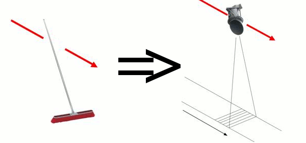
To talk about the device and the operation of the CCD matrix, first briefly talk about the features of push-broom shooting. The analogy of shooting in the direction of movement of the spacecraft with a brush turned out because of the same principle: you run the brush on the floor, gradually erasing dust, and HiRISE captures the image not entirely, but sequentially scanning the surface of Mars.
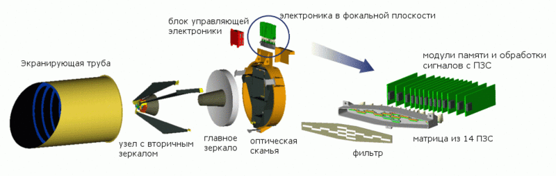
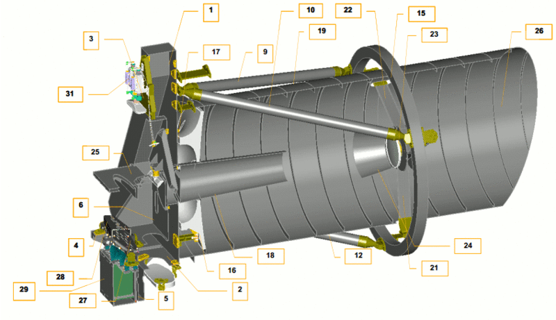
As in the case of a brush, the width of the grip, i.e. how much “dust” we manage to collect in a single pass depends on the number of detectors, while the length depends on how many rows of pixels will be combined into the final image. Here, the scientists controlling the camera from the Earth have to choose between which part of the surface they can photograph and the amount of data they can store and process in the device (and then they can also transfer them to the Earth). By the way, an important aspect in determining the amount of work is the “temperature regime” of HiRISE. To monitor its condition, there are 35 temperature sensors on the device (in the picture external sensors 7, 8, 11, 13, 14, 20, 30 and internal 32-35 are not marked, since the picture is given in section).
So, the width of the capture area depends on the number of sensors. In the focal plane of HiRISE there is a subsystem consisting of an aluminum-carbon frame, a spectral filter and memory modules and CCD signal processing.
Each CCD contains 2048 pixels with a physical size of 12 μm, located in the direction opposite to the MRO movement, and 128 integration elements with time delay integration (TDI), which are located in the direction of movement of the device. All 14 CCDs are zigzag-shaped with an overlap of 48 px, which provides a continuous capture area width of about 20000 px in the red range and about 4048 in blue-green and near infrared. Power supply of the device allows simultaneous operation of at least 10 CCDs.
Using TDI increases the exposure time and allows you to achieve both very high resolutions and a high signal-to-noise ratio (which is 200: 1 for the red range and 100: 1 for the rest). When the spacecraft flies over the surface of Mars, the TDI combines the signals passing through the CCD detectors by shifting the accumulated signal to the next row (ruler) of the CCD at the same frequency as the image moves. Here is an example of using four-phase TDI:
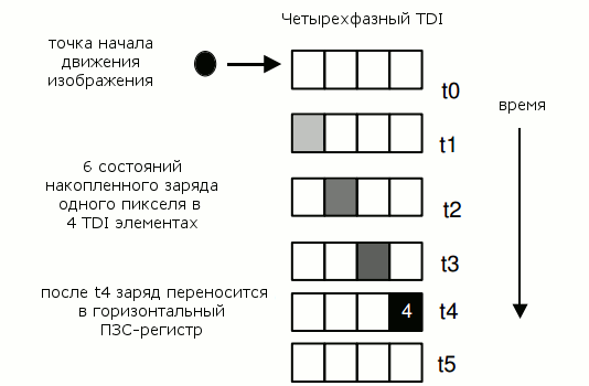
The frequency of changing lines (13,000 lines per second) corresponds to 76 microseconds per line when the vehicle is 250 km above the surface. The integration time of the pixels is chosen in such a way as to correspond to the speed relative to the ground so that the charge from one section of the image is consistently coordinated with the next element along the path of the vehicle. The photodetector can use 8,32, 64 and 128 levels of TDI (detector elements located along the shooting bar) so that the overall luminance of the image corresponds to the sensitivity of the CCD. Possible image blur due to the rotation of the planet is compensated by the position of the device on the vertical axis (“yaw”).
The electronic components of the memory module and CCD signal processing minimize the number of active and passive elements capable of “noisy” image. The conversion chain between the CCD output amplifier and the 14-bit A / D converter (delivering 80 MSa / s) is designed to create less noise than the CCD, while remaining resistant to radiation and undemanding power. Each of the 14 modules for control, signal processing, compression and data storage uses a matrix of logic elements with Xilinx Virtex 300E operational programming with additional protection from radiation. The matrix is a static RAM (SRAM), which allows you to reflash it during operation.
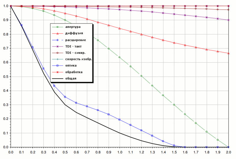
The estimated maximum signal for the red channel is 76 thousand electrons at an altitude of 300 km without the use of binning. The following picture shows a graph of the signal-to-noise ratio (SNR) as a function of the height of the vehicle and the surface albedo in all three ranges:

But the transfer function of the modulation depending on various factors (on the horizontal axis - the spatial resolution, the maximum signal frequency (Nyquist) 41.7 lp / mm).
Yes, according to the text, binning was mentioned several times. In short, this is a way to get data from the camera, in which information comes not from each pixel, but from a group of pixels forming one “superpixel”.
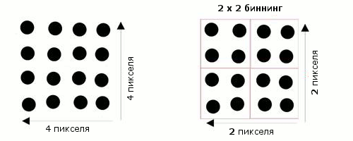
This superpixel contains light data from all four pixels, which makes it 4 times brighter than the original pixels. At the same time, the pixels themselves become 4 times smaller. Since binning is performed by HiRISE equipment, this parameter cannot be changed later. Here is an example of 4 x 4 binning:
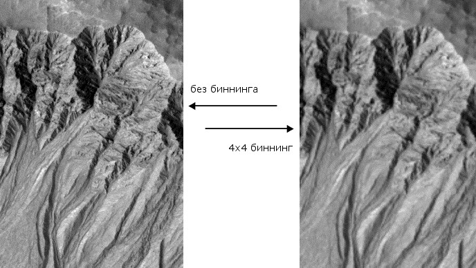
The logical question is: once binning reduces spatial resolution, why use it at all? The answer is simple: when the image is too dark, it is so grainy that you can’t see the small details anyway, which means we won’t lose anything if we set the correct exposure using binning. Another important aspect is the limited amount of local storage. And in the end, not all areas need a great deal of detail. If a resolution of 1 meter per pixel is not required, then it is quite possible to use binning and not to overload the equipment once again.
As for the organization of the shooting, then, in general, everything is standard. The coordinates of the target area, which is required to be removed, are poured onto the spacecraft during the next communication session. The device translates them into the time in which it will fly over a given area. At the appropriate moment, previously transmitted commands are executed that initialize the exposure. Commands include the following parameters: time per line, number of lines, binning, number of TDI levels, conversion table for converting 14-bit data to 8-bit. Approximately 5 seconds before exposure begins, analogue systems begin to receive power.
At a given time, all detectors are turned on and synchronized simultaneously. As soon as the last signal passes through the last detector, the power is turned off, and the collected data is sequentially read from each memory module for subsequent transmission to Earth. Each data category transmitted has its own heading, so that these data can be correctly interpreted later. Optionally, the data can be compressed without loss of quality by an embedded hardware device connected to the SSR. It takes from 4 to 48 hours to transfer 20 Mpx images, depending on the compression parameters and the distance to the Earth.
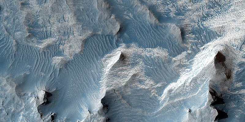
And already on Earth we can enjoy such pictures.
PS If you are interested in the topic, I can continue in the direction of forming / processing commands from the Earth and on the device itself, as well as affect the HiRISE software interface.
PPS If you find inaccuracies in the terminology or any other errors - welcome to the PM. There is also taken objective criticism of any other aspects of the article.
Dry facts
| Parameter | Value |
|---|---|
| Resolution | 25-50 cm / pixel |
| Spectral range | blue-green (400-600 nm) red (550-850 nm) near infrared (800-1000 nm) |
| Bandwidth | 6 km (red) 1.2 km (blue-green and near infrared) |
| Telescope aperture | 50 cm, f / 24 |
| Viewing angles | 1.43 ° x 0.1 ° |
| Angular resolution | 1 x 1 micro radian |
| Focal length | 9.6 m |
| Weight | TOTAL - 40 kg, including: telescope optics - 10 kg; structural elements - 13.6 kg; electronic system in the focal plane - 2.3 kg; control electronics - 3.6 kg; cables / wiring - 1.2 kg; other - 9.3 kg |
| Dimensions | telescope - 113 cm x 59 cm (diameter) control electronics - 16 x 15 x 7 cm |
| Power consumption | shooting images <125 W processing <40 W maximum average power consumption - 50 W |
| Detector Set | 2 in the blue-green range, 4048 px, signal / noise ratio = 100: 1 10 in the red range, 20264 px, signal / noise ratio = 200: 1 2 in the near-infrared range, 4048 px, signal / noise ratio = 100: 1 |
| Exposition | up to 128 time delay integration lines |
| Data compression | 14-bit analog-digital converters; compression from 14 to 8 bits in real time; 1-16 pixel binning; two-time lossless compression on SSD (more precisely, SSR - Solid State Recorder) |
| Camera memory | 28 Gbps (one full-sized uncompressed image takes 16.4 Gbps) |
| Data transfer rate | 20 Mbps |
Let's start with the story. Which was born in the late 80s by the efforts of Alan Delamere from Ball Aerospace. Alan began to design a camera that could shoot remote objects with very high resolution. However, in practice, it was not until the 2000s that the University of Arizona began preparing the multi-function automatic interplanetary station MRO (Mars Reconnaissance Orbiter) to translate its ideas. Having united with the scientists of the University in 2001, NASA obtained principal agreement on the installation of such a camera in the MRO and on August 12, 2005 it was successfully installed:
')
I think there is not much point in describing the goals of the mission, the HiRISE journey to Mars, the famous family portrait of the Earth and the Moon , temporary misadventures with equipment, etc., all this can be found in the corresponding article in Wikipedia .
But what is not there is a device HiRISE and features of its equipment.
The main components of HiRISE as a whole roughly correspond to the device of any space telescope: optical system and control electronics :)
But since the camera was required to take pictures of the features of the Martian surface (both already known and not detected earlier) with high resolution and contrast, it had to have not only a wide capture band, but also a very good signal-to-noise ratio. And if we add to this the limitations on mass, budget, project deadlines, and a huge ground speed of flight (3.4 km / s), then the achievement of these shooting parameters is clearly not a trivial task.
The photodetector of the device is an astigmatic reflecting telescope with a system of 3 mirrors. HiRISE uses lightweight Zerodur optics and carbon fiber composite materials. The use of carbon fiber gives a light but stiff frame and low absorption with a low coefficient of swelling. Composite elements with a negative thermal expansion in combination with metal compounds (having a positive coefficient of expansion) avoid the deformation of the structure.
The use of a Cassegrain circuit in the lens (see picture) with wrapping optics and two mirrors was optimized to work at the level of the diffraction limit with a narrow band of coverage, which is obtained when shooting along the motion of the spacecraft (the so-called push-broom shooting, which will be discussed further ). Filters in front of the detectors divide the light flux into 3 spectral ranges: red (panchromatic), blue-green and near-infrared.
The CCDs are zigzagged to close the entire aisle area, without any gaps. The blue-green and near-infrared ranges each have 2 detectors with a total bandwidth of 4048 px, 10 for the red band there are 10 detectors with a total width of 20264 px.
The 50 cm main mirror has a double-arch design for weight reduction and increased strength. Color filters are located 30 mm from the detectors, which allows to avoid problems due to ambient light and multiple reflections of the quasi-collimated beam. Lyot's stop (Lyot stop), located between the tertiary and the second folding mirror, makes it possible to almost completely eliminate stray light.
To talk about the device and the operation of the CCD matrix, first briefly talk about the features of push-broom shooting. The analogy of shooting in the direction of movement of the spacecraft with a brush turned out because of the same principle: you run the brush on the floor, gradually erasing dust, and HiRISE captures the image not entirely, but sequentially scanning the surface of Mars.
As in the case of a brush, the width of the grip, i.e. how much “dust” we manage to collect in a single pass depends on the number of detectors, while the length depends on how many rows of pixels will be combined into the final image. Here, the scientists controlling the camera from the Earth have to choose between which part of the surface they can photograph and the amount of data they can store and process in the device (and then they can also transfer them to the Earth). By the way, an important aspect in determining the amount of work is the “temperature regime” of HiRISE. To monitor its condition, there are 35 temperature sensors on the device (in the picture external sensors 7, 8, 11, 13, 14, 20, 30 and internal 32-35 are not marked, since the picture is given in section).
But the sensor codes for the classifier Planetary Data System
1 - MRO: OPT_BNCH_FLEXURE_TEMPERATURE
2 - MRO: OPT_BNCH_MIRROR_TEMPERATURE
3 - MRO: OPT_BNCH_FOLD_FLAT_TEMPERATURE
4 - MRO: OPT_BNCH_FPA_TEMPERATURE
5 - MRO: OPT_BNCH_FPE_TEMPERATURE
6 - MRO: OPT_BNCH_LIVING_RM_TEMPERATURE
7 - MRO: OPT_BNCH_BOX_BEAM_TEMPERATURE
8 - MRO: OPT_BNCH_COVER_TEMPERATURE
9 - MRO: MS_TRUSS_LEG_0_A_TEMPERATURE
10 - MRO: MS_TRUSS_LEG_0_B_TEMPERATURE
11 - MRO: MS_TRUSS_LEG_120_A_TEMPERATURE
12 - MRO: MS_TRUSS_LEG_120_B_TEMPERATURE
13 - MRO: MS_TRUSS_LEG_240_A_TEMPERATURE
14 - MRO: MS_TRUSS_LEG_240_B_TEMPERATURE
15 - MRO: SEC_MIRROR_MTR_RNG_TEMPERATURE
16 - MRO: PRIMARY_MIRROR_MNT_TEMPERATURE
17 - MRO: PRIMARY_MIRROR_TEMPERATURE
18 - MRO: PRIMARY_MIRROR_BAF_TEMPERATURE
19 - MRO: BARREL_BAFFLE_TEMPERATURE
20 - MRO: SPIDER_LEG_30_TEMPERATURE
21 - MRO: SPIDER_LEG_150_TEMPERATURE
22 - MRO: SPIDER_LEG_270_TEMPERATURE
23 - MRO: SEC_MIRROR_TEMPERATURE
24 - MRO: SEC_MIRROR_BAFFLE_TEMPERATURE
25 - MRO: FIELD_STOP_TEMPERATURE
26 - MRO: SUN_SHADE_TEMPERATURE
27 - MRO: FPA_POSITIVE_Y_TEMPERATURE
28 - MRO: FPA_NEGATIVE_Y_TEMPERATURE
29 - MRO: FPE_TEMPERATURE
30 - MRO: IEA_TEMPERATURE
31 - MRO: FOCUS_MOTOR_TEMPERATURE
32 - MRO: INST_CONT_BOARD_TEMPERATURE
33 - MRO: MECH_TLM_BOARD_TEMPERATURE
34 - MRO: CPMM_PWS_BOARD_TEMPERATURE
35 - MRO: IE_PWS_BOARD_TEMPERATURE
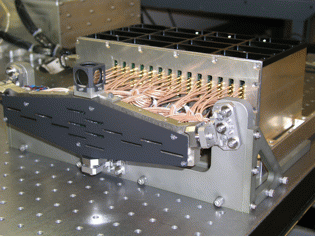
So, the width of the capture area depends on the number of sensors. In the focal plane of HiRISE there is a subsystem consisting of an aluminum-carbon frame, a spectral filter and memory modules and CCD signal processing.
Each CCD contains 2048 pixels with a physical size of 12 μm, located in the direction opposite to the MRO movement, and 128 integration elements with time delay integration (TDI), which are located in the direction of movement of the device. All 14 CCDs are zigzag-shaped with an overlap of 48 px, which provides a continuous capture area width of about 20000 px in the red range and about 4048 in blue-green and near infrared. Power supply of the device allows simultaneous operation of at least 10 CCDs.
Using TDI increases the exposure time and allows you to achieve both very high resolutions and a high signal-to-noise ratio (which is 200: 1 for the red range and 100: 1 for the rest). When the spacecraft flies over the surface of Mars, the TDI combines the signals passing through the CCD detectors by shifting the accumulated signal to the next row (ruler) of the CCD at the same frequency as the image moves. Here is an example of using four-phase TDI:
The frequency of changing lines (13,000 lines per second) corresponds to 76 microseconds per line when the vehicle is 250 km above the surface. The integration time of the pixels is chosen in such a way as to correspond to the speed relative to the ground so that the charge from one section of the image is consistently coordinated with the next element along the path of the vehicle. The photodetector can use 8,32, 64 and 128 levels of TDI (detector elements located along the shooting bar) so that the overall luminance of the image corresponds to the sensitivity of the CCD. Possible image blur due to the rotation of the planet is compensated by the position of the device on the vertical axis (“yaw”).
The electronic components of the memory module and CCD signal processing minimize the number of active and passive elements capable of “noisy” image. The conversion chain between the CCD output amplifier and the 14-bit A / D converter (delivering 80 MSa / s) is designed to create less noise than the CCD, while remaining resistant to radiation and undemanding power. Each of the 14 modules for control, signal processing, compression and data storage uses a matrix of logic elements with Xilinx Virtex 300E operational programming with additional protection from radiation. The matrix is a static RAM (SRAM), which allows you to reflash it during operation.
The estimated maximum signal for the red channel is 76 thousand electrons at an altitude of 300 km without the use of binning. The following picture shows a graph of the signal-to-noise ratio (SNR) as a function of the height of the vehicle and the surface albedo in all three ranges:
But the transfer function of the modulation depending on various factors (on the horizontal axis - the spatial resolution, the maximum signal frequency (Nyquist) 41.7 lp / mm).
Yes, according to the text, binning was mentioned several times. In short, this is a way to get data from the camera, in which information comes not from each pixel, but from a group of pixels forming one “superpixel”.
This superpixel contains light data from all four pixels, which makes it 4 times brighter than the original pixels. At the same time, the pixels themselves become 4 times smaller. Since binning is performed by HiRISE equipment, this parameter cannot be changed later. Here is an example of 4 x 4 binning:
The logical question is: once binning reduces spatial resolution, why use it at all? The answer is simple: when the image is too dark, it is so grainy that you can’t see the small details anyway, which means we won’t lose anything if we set the correct exposure using binning. Another important aspect is the limited amount of local storage. And in the end, not all areas need a great deal of detail. If a resolution of 1 meter per pixel is not required, then it is quite possible to use binning and not to overload the equipment once again.
As for the organization of the shooting, then, in general, everything is standard. The coordinates of the target area, which is required to be removed, are poured onto the spacecraft during the next communication session. The device translates them into the time in which it will fly over a given area. At the appropriate moment, previously transmitted commands are executed that initialize the exposure. Commands include the following parameters: time per line, number of lines, binning, number of TDI levels, conversion table for converting 14-bit data to 8-bit. Approximately 5 seconds before exposure begins, analogue systems begin to receive power.
At a given time, all detectors are turned on and synchronized simultaneously. As soon as the last signal passes through the last detector, the power is turned off, and the collected data is sequentially read from each memory module for subsequent transmission to Earth. Each data category transmitted has its own heading, so that these data can be correctly interpreted later. Optionally, the data can be compressed without loss of quality by an embedded hardware device connected to the SSR. It takes from 4 to 48 hours to transfer 20 Mpx images, depending on the compression parameters and the distance to the Earth.
And already on Earth we can enjoy such pictures.
And finally, some more interesting facts about HiRISE
HiRISE's philosophy is “People’s Camera”.
A team of scientists is not a group gathered in one room, but people in different parts of the Earth.
Image processing and publishing them on the web is automated (takes from several days to several weeks).
Analysis tools are based on web technologies.
A team of scientists is not a group gathered in one room, but people in different parts of the Earth.
Image processing and publishing them on the web is automated (takes from several days to several weeks).
Analysis tools are based on web technologies.
PS If you are interested in the topic, I can continue in the direction of forming / processing commands from the Earth and on the device itself, as well as affect the HiRISE software interface.
PPS If you find inaccuracies in the terminology or any other errors - welcome to the PM. There is also taken objective criticism of any other aspects of the article.
Source: https://habr.com/ru/post/182584/
All Articles