The beauty and power of the Qt Graphics View Framework by example
In my opinion, Qt Graphics Scene FrameWork is a powerful tool, unfairly deprived of attention on Habré. I will try to rectify the situation by devoting a series of articles to him. And in this pilot article, I will show you how to program with this wonderful framework using the example of a more or less real task.
And as such a task, I chose to build graphs. It has everything:
At once I will make a reservation that the code provided below demonstrates only the main chips used. The full version, if anyone is curious can take here .
The first convenience of the framework opens already at the design stage. So, the work plan, which is prompted by the architecture of our tool:
We compose:
')
Now let's start drawing the grid. It should be noted that initially it seemed that the labels should be drawn along with the coordinate lines. However, this approach goes against the declarative ideology of the framework: to describe how an item should look like in the simplest case, and then tell the scene how it should deal with it, and get the perfect picture in any conditions at the output. And in the end, the layout of the serif was moved to compose.
For now, let's do without them and draw a simple grid. Our main idea: gridItem to draw in the same scale as the data graphs, and let Qt do the translation into the displayed coordinates. If we now make the schedule a descendant of the gridItem, then we have a ready-made solution:
Implementation:
There is one subtle point: when you increase our gridItem using QTransform, the brush size also grows, so that this does not happen, you need to set QPen as a cosmetic:
The implementation of the graph is extremely simple and most of the code is taken up by finding the boundRect boundaries.
In fact, we already have a solution, it is obvious if we pay attention to the fact that GraphicsDataItem is inherited from QGraphicsObject and that signals are already declared in the class body. Those. interaction between the objects of the scene occurs in the usual way - through signals and slots.
And what do we have in the subjective result?
To evaluate the real convenience and calibrate our subjective feeling let's compare the amount of work done by us and what the respected developers of qwt did:
Documentation expanded with examples.
Video , if you can not download from the off site, then quietly located on youtube
The project .
PS The project is a demonstration, but if bugs are found, or who helps with the improvement, I will be only too happy.
PPS Just in case: the text is published under the license CC-BY 3.0
UPD totals:
And as such a task, I chose to build graphs. It has everything:
- Different types of objects: both text and various combinations of primitives
- The task of the composition: it is necessary to arrange the title, the captions to the axes, and the coordinate area itself with graphs
- The tasks of converting from one coordinate to another: from the frame of reference associated with the data into the displayed
- The interaction between the elements: at least when adding, deleting and changing the schedule update the legend.
At once I will make a reservation that the code provided below demonstrates only the main chips used. The full version, if anyone is curious can take here .
The first convenience of the framework opens already at the design stage. So, the work plan, which is prompted by the architecture of our tool:
- Let's create a scene on which we will draw graphs: compose axis labels and a coordinate area.
- Create a grid (And here we decide what we do with the graphs).
- Create an Item for the chart.
- Create a legend.
First stage. Creating a composition.
Hidden text
class GraphicsPlotNocksTube : public QGraphicsItem { public: GraphicsPlotNocksTube(QGraphicsItem *parent): QGraphicsItem(parent){} void updateNocks(const QList<QGraphicsSimpleTextItem*>& nocks); QRectF boundingRect()const {return m_boundRect;} void paint(QPainter *, const QStyleOptionGraphicsItem *, QWidget *){} inline const QFont &font(){return m_NocksFont;} private: QList<QGraphicsSimpleTextItem*> m_nocks; QFont m_NocksFont; QPen m_nockPen; QRectF m_boundRect; }; class Graphics2DPlotGrid: public QGraphicsItem { public: Graphics2DPlotGrid(QGraphicsItem * parent); QRectF boundingRect() const; const QRectF & rect() const; void setRange(int axisNumber, double min, double max); void setMainGrid(int axisNumber, double zero, double step); void setSecondaryGrid(int axisNumber, double zero, double step); void setMainGridPen(const QPen & pen); void setSecondaryGridPen(const QPen &pen); inline QPen mainGridPen(){return m_mainPen;} inline QPen secondaryGridPen(){return m_secondaryPen;} void paint(QPainter *painter, const QStyleOptionGraphicsItem *option, QWidget *widget); public: struct AxisGuideLines { AxisGuideLines(): showLines(true){} QVector<QLineF> lines; bool showLines; }; AxisGuideLines abscissMainLines; AxisGuideLines abscissSecondaryLines; AxisGuideLines ordinateMainLines; AxisGuideLines ordinateSecondaryLines; private: void paintAxeGuidLines(const AxisGuideLines& axe, QPainter *painter, const QPen &linePen); QPen m_mainPen; QPen m_secondaryPen; QRectF m_rect; }; void Graphics2DPlotGrid::paint(QPainter *painter, const QStyleOptionGraphicsItem *option, QWidget *widget) { Q_UNUSED(option) Q_UNUSED(widget) paintAxeGuidLines(abscissSecondaryLines, painter, m_secondaryPen); paintAxeGuidLines(abscissMainLines, painter, m_mainPen); paintAxeGuidLines(ordinateSecondaryLines, painter, m_secondaryPen); paintAxeGuidLines(ordinateMainLines, painter, m_mainPen); painter->setPen(m_mainPen); painter->drawRect(m_rect); } class GraphicsPlotItemPrivate { Q_DECLARE_PUBLIC(GraphicsPlotItem) GraphicsPlotItem* q_ptr; GraphicsPlotItemPrivate(GraphicsPlotItem* parent); void compose(); void calculateAndSetTransForm(); void autoSetRange(); void autoSetGrid(); void calculateOrdinateGrid(); void calculateAbscissGrid(); void setAxisRange(int axisNumber, double min, double max); Graphics2DPlotGrid * gridItem; QGraphicsSimpleTextItem * abscissText; QGraphicsSimpleTextItem * ordinateText; QGraphicsSimpleTextItem *titleText; QFont titleFont; QFont ordinaateFont; QFont abscissFont; QRectF rect; QRectF m_sceneDataRect; GraphicsPlotLegend *m_legend; GraphicsPlotNocksTube* ordinateMainNocks; GraphicsPlotNocksTube* ordinateSecondaryNocks; GraphicsPlotNocksTube* abscissSecondaryNocks; GraphicsPlotNocksTube* abscissMainNocks; struct Range{ double min; double max; }; struct AxisGuideLines { AxisGuideLines():baseValue(0.0), step(0.0){} double baseValue; double step; }; AxisGuideLines abscissMainLines; AxisGuideLines abscissSecondaryLines; AxisGuideLines ordinateMainLines; AxisGuideLines ordinateSecondaryLines; Range abscissRange; Range ordinateRange; bool isAutoGrid; bool isAutoSecondaryGrid; public: void range(int axisNumber, double *min, double *max); }; We compose:
void GraphicsPlotItemPrivate::compose() { titleText->setFont(titleFont); abscissText->setFont(abscissFont); if(titleText->boundingRect().width() > rect.width()){ //TODO case when titleText too long } //Composite by height qreal dataHeight = rect.height() - 2*titleText->boundingRect().height() - 2*(abscissText->boundingRect().height()); if(dataHeight < 0.5*rect.height()){ //TODO decrease font size } titleText->setPos((rect.width()-titleText->boundingRect().width())/2.0, rect.y()); //Compose by width qreal dataWidth = rect.width()-2*ordinateText->boundingRect().height(); if(dataWidth< 0.5*rect.width()){ //TODO decrease font size } ordinateMainNocks->setPos(-ordinateMainNocks->boundingRect().width(), -5*ordinateMainNocks->font().pointSizeF()/4.0); m_sceneDataRect.setRect(rect.width()-dataWidth, 2*titleText->boundingRect().height() , dataWidth, dataHeight); abscissText->setPos( (dataWidth - abscissText->boundingRect().width())/2.0 + m_sceneDataRect.y(), rect.bottom() - abscissText->boundingRect().height()); ordinateText->setPos(0, (dataHeight - ordinateText->boundingRect().width())/2.0 + m_sceneDataRect.y()); calculateAndSetTransForm(); q_ptr->update() } ')
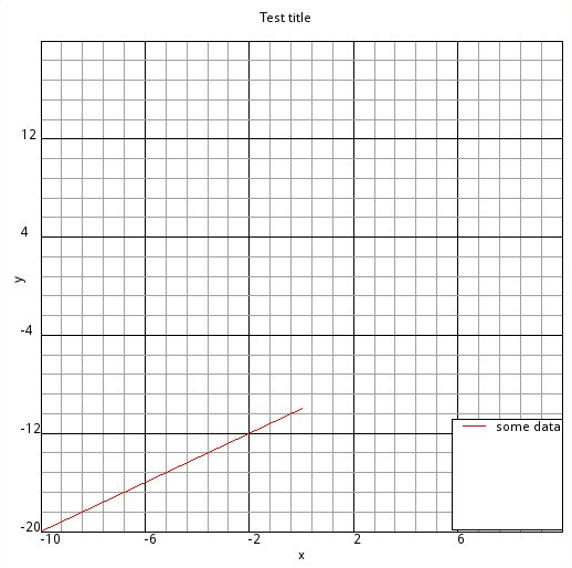
Creating a grid
Now let's start drawing the grid. It should be noted that initially it seemed that the labels should be drawn along with the coordinate lines. However, this approach goes against the declarative ideology of the framework: to describe how an item should look like in the simplest case, and then tell the scene how it should deal with it, and get the perfect picture in any conditions at the output. And in the end, the layout of the serif was moved to compose.
For now, let's do without them and draw a simple grid. Our main idea: gridItem to draw in the same scale as the data graphs, and let Qt do the translation into the displayed coordinates. If we now make the schedule a descendant of the gridItem, then we have a ready-made solution:
- We just need to draw the lines of the graph in the data scale. They themselves will be displayed in the desired area, and if you add
this solves the problem of cropping the graphicsgridItem->setFlag(QGraphicsItem::ItemClipsChildrenToShape) - All scene events (such as keyboard events or mouse events will automatically be transferred to the data scale, which simplifies their processing.
Implementation:
void Graphics2DPlotGrid::paint(QPainter *painter, const QStyleOptionGraphicsItem *option, QWidget *widget) { Q_UNUSED(option) Q_UNUSED(widget) paintAxeGuidLines(abscissSecondaryLines, painter, m_secondaryPen); paintAxeGuidLines(abscissMainLines, painter, m_mainPen); paintAxeGuidLines(ordinateSecondaryLines, painter, m_secondaryPen); paintAxeGuidLines(ordinateMainLines, painter, m_mainPen); painter->setPen(m_mainPen); painter->drawRect(m_rect); } void Graphics2DPlotGrid::paintAxeGuidLines(const AxisGuideLines& axe, QPainter *painter, const QPen &linePen) { if(axe.showLines){ painter->setPen(linePen); painter->drawLines(axe.lines); } } void GraphicsPlotItemPrivate::calculateAndSetTransForm() { double scaleX = m_sceneDataRect.width()/gridItem->rect().width(); double scaleY = m_sceneDataRect.height()/gridItem->rect().height(); QTransform transform = QTransform::fromTranslate( - gridItem->rect().x()*scaleX + m_sceneDataRect.x(), - gridItem->rect().y()*scaleY +m_sceneDataRect.y()); transform.scale(scaleX, -scaleY); gridItem->setTransform(transform); ordinateMainNocks->setTransform(transform); // ordinateSecondaryNocks->setTransform(transform); abscissMainNocks->setTransform(transform); // abscissSecondaryNocks->setTransform(transform); } calculate the grid
void GraphicsPlotItemPrivate::calculateOrdinateGrid() { const QRectF r = gridItem->boundingRect(); if(fabs(r.width()) < std::numeric_limits<float>::min()*5.0 || fabs(r.height()) < std::numeric_limits<float>::min()*5.0) return; QList<QGraphicsSimpleTextItem*> nocksList; auto calculteLine = [&] (AxisGuideLines* guides, QVector<QLineF> *lines) { int k; double minValue; int count; nocksList.clear(); if(fabs(guides->step) > std::numeric_limits<double>::min()*5.0 ) { k = (ordinateRange.min - guides->baseValue)/guides->step; minValue = k*guides->step+guides->baseValue; count = (ordinateRange.max - minValue)/guides->step; //TODO , if( count >0){ lines->resize(count); nocksList.reserve(count); double guidCoordinate; for(int i = 0; i< count; i++){ guidCoordinate = minValue+i*guides->step; lines->operator[](i) = QLineF(abscissRange.max, guidCoordinate, abscissRange.min, guidCoordinate); nocksList.append(new QGraphicsSimpleTextItem(QString::number(guidCoordinate))); nocksList.last()->setPos(abscissRange.min, guidCoordinate); } } else lines->clear(); } else lines->clear(); }; calculteLine(&ordinateMainLines, &(gridItem->ordinateMainLines.lines)); ordinateMainNocks->updateNocks(nocksList); calculteLine(&ordinateSecondaryLines, &(gridItem->ordinateSecondaryLines.lines)); ordinateSecondaryNocks->updateNocks(nocksList); } There is one subtle point: when you increase our gridItem using QTransform, the brush size also grows, so that this does not happen, you need to set QPen as a cosmetic:
m_secondaryPen.setCosmetic(true); m_mainPen.setCosmetic(true); Item Graphics
Class declaration
class GraphicsDataItem: public QGraphicsObject { Q_OBJECT public: GraphicsDataItem(QGraphicsItem *parent =0); ~GraphicsDataItem(); void setPen(const QPen& pen); QPen pen(); void setBrush(const QBrush & brush); QBrush brush(); void ordinateRange(double *min, double *max); void abscissRange(double *min, double *max); void setTitle(const QString & title); QString title(); inline int type() const {return GraphicsPlot::DataType;} Q_SIGNALS: void dataItemChange(); void penItemChange(); void titleChange(); protected: void setOrdinateRange(double min, double max); void setAbscissRange(double min, double max); private: Q_DECLARE_PRIVATE(GraphicsDataItem) GraphicsDataItemPrivate *d_ptr; }; class Graphics2DGraphItem: public GraphicsDataItem { Q_OBJECT public: Graphics2DGraphItem(QGraphicsItem *parent =0); Graphics2DGraphItem(double *absciss, double *ordinate, int length, QGraphicsItem *parent =0); ~Graphics2DGraphItem(); void setData(double *absciss, double *ordinate, int length); void setData(QList<double> absciss, QList<double> ordinate); void setData(QVector<double> absciss, QVector<double> ordinate); QRectF boundingRect() const; void paint(QPainter *painter, const QStyleOptionGraphicsItem *option, QWidget *widget); private: Q_DECLARE_PRIVATE(Graphics2DGraphItem) Graphics2DGraphItemPrivate *d_ptr; }; The implementation of the graph is extremely simple and most of the code is taken up by finding the boundRect boundaries.
class Graphics2DGraphItemPrivate { Q_DECLARE_PUBLIC(Graphics2DGraphItem) Graphics2DGraphItem *q_ptr; Graphics2DGraphItemPrivate(Graphics2DGraphItem *parent):q_ptr(parent){} QVector<QLineF> m_lines; template<typename T> void setData(T absciss, T ordinate, qint32 length) { q_ptr->prepareGeometryChange(); --length; m_lines.resize(length); Range ordinateRange; ordinateRange.min = ordinate[0]; ordinateRange.max = ordinate[0]; Range abscissRange; abscissRange.min = absciss[0]; abscissRange.max = absciss[0]; for(int i =0; i < length; ++i) { if(ordinate[i+1] > ordinateRange.max) ordinateRange.max = ordinate[i+1]; else if(ordinate[i+1] < ordinateRange.min ) ordinateRange.min = ordinate[i+1]; if(absciss[i+1] > abscissRange.max) abscissRange.max = absciss[i+1]; else if(absciss[i+1] < abscissRange.min ) abscissRange.min = absciss[i+1]; m_lines[i].setLine(absciss[i], ordinate[i], absciss[i+1], ordinate[i+1]); } m_boundRect.setRect(abscissRange.min, ordinateRange.min, abscissRange.max - abscissRange.min, ordinateRange.max - abscissRange.min); q_ptr->setOrdinateRange(ordinateRange.min, ordinateRange.max); q_ptr->setAbscissRange(abscissRange.min, abscissRange.max); q_ptr->update(); QMetaObject::invokeMethod(q_ptr, "dataItemChange"); } QRect m_boundRect; }; QRectF Graphics2DGraphItem::boundingRect() const { return d_ptr->m_boundRect; } void Graphics2DGraphItem::paint(QPainter *painter, const QStyleOptionGraphicsItem *option, QWidget *widget) { Q_UNUSED(option) Q_UNUSED(widget) painter->setBrush(brush()); painter->setPen(pen()); painter->drawLines(d_ptr->m_lines); } Legend and class interaction
In fact, we already have a solution, it is obvious if we pay attention to the fact that GraphicsDataItem is inherited from QGraphicsObject and that signals are already declared in the class body. Those. interaction between the objects of the scene occurs in the usual way - through signals and slots.
Subjective result
And what do we have in the subjective result?
- Trouble-free development of architecture, if you follow the logic of the framework.
- All elements are written in declarative style and the main code refers to the essence and to a large extent to the dancing around.
- Prostate create item-s to display data
Qwt comparison and calibration.
To evaluate the real convenience and calibrate our subjective feeling let's compare the amount of work done by us and what the respected developers of qwt did:
- The first thing that catches your eye is the huge listings in drawItem. Ours much shorter. We do not need to worry about optimizing the rendering of each member. We do it once and in one place - when we set the viewport ..
- A lot of papers are invested in QwtLegendData, QwtLegendLabel, QwtPainter, QwtPainterCommand, QwtPlotDirectPainter, etc. We did not do all this and the reasons for why we should implement all this in our situation are not clear.
- We don’t need to write our own transformation and recalculation classes from one system to another, and we don’t need to manually transform coordinates.
- We have achieved much more abstraction of iems with data.
- Our class hierarchy is an order of magnitude simpler. And with further expansion there are no reasons why it should become more difficult.
Links
Documentation expanded with examples.
Video , if you can not download from the off site, then quietly located on youtube
The project .
PS The project is a demonstration, but if bugs are found, or who helps with the improvement, I will be only too happy.
PPS Just in case: the text is published under the license CC-BY 3.0
UPD totals:
Source: https://habr.com/ru/post/182142/
All Articles