Wireless Arduino Network
The micro controller on the Arduino platform is an excellent platform for hobby projects of varying degrees of complexity and utility. I will not argue that the Arduino platform is the best choice for professional solutions (I would rather agree with the opposite), but for my amateur "crafts" in the field of home automation this is the best option. Those. the controller is good on its own, but if it also ceases to be “on its own”, but will be able to “communicate” with its own kind, while not overgrowing with additional wires, its usefulness and applicability can grow many times over. So, let's start building our home SkyNet ...
The basis of our network will take the budget radio modules operating at a frequency of 433.90MHz. The cost of one such module is about $ 2.5, so the costs are small in order to organize communication with the outside world. Of course, you can also use ready-made ethernet modules for communication and even create a symbiosis with wireless routers based on alternative firmware, but in many cases it is easier and cheaper to do everything on such radio modules.
Transmitter:

')
Receiver:
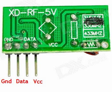
The quality of work and range of communication of these modules leaves much to be desired, and I would not believe the optimistic statements of sellers about the range of "> 500m". At best, 100 meters in open areas, well, much less in the presence of concrete partitions. However, for an apartment or a small suburban area they will be enough. You can use higher-quality (and, accordingly, more expensive) radio modules, so the article can be considered as an ideological concept applicable to many possible variants of implementation.
Important point: in this manual I will not consider the option of creating a network with quality control of data transfer. If the comparison with ethernet protocols can be considered appropriate, then we will not build a network for transmitting TCP packets, but rather, UDP.
Each of the modules is connected to the controller in an elementary manner - the power is supplied via the Vcc / Gnd and the Data pin is connected to the free digital input on the micro controller. To improve the quality of reception / transmission, it is recommended to additionally connect an antenna in the form of a wire of 10-15 cm in size. By the way, the communication distance also depends on the power supplied to the power supply module - if they are powered from 12V, the communication range and reliability of communication increases significantly.
Receiver and transmitter connected to the Arduino UNO R3 micro controller:
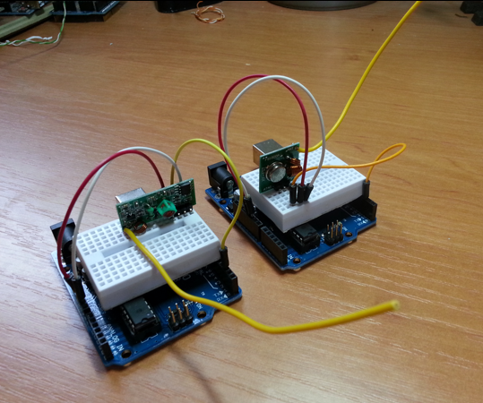
Thus, we made two devices: the first is a transmitter that will “broadcast” some information on the air; the second is the receiver, which, accordingly, will air "listen". Further, the matter is that the transmission and reception would be meaningful and useful for us.
What is good about the Arduino platform is the presence of a huge number of ready-made libraries for working with various devices. You can, of course, work with radio modules without any libraries, but then you need to develop your own communication protocol with checksums and other things. Fortunately, there is a wonderful VirtualWire library that supports data (and similar) radio modules. With the help of this library it is very easy to organize the transmission and reception of small packets of information.
Usage principle: on the transmitter we form a data set for sending (in the form of a string of characters or byte codes), and on the receiver, when we receive the "correct" data packet, we display them. The easiest way to see this is with examples that come with the library itself.
Transmitter code using VirtualWire (from library use examples):
Receiver code:
The next step will be to reach a new level of abstraction, namely the development of a typical package structure, which all our devices will exchange. This will allow in the future to connect to our network new equipment that can use signals from existing devices.
I will give the data structure that seemed optimal to me with the available hardware capabilities. So, here is a list of the main parameters that are broadcast with each package:
device_id - identifier of the device that sent the packet. Data type: unsigned int (length 2 bytes, value range from 0 to 65535) - as it seems to me, it is quite enough for a home network.
destination_id is the device identifier to whom the packet is intended. The data type is the same as device_id. It is important to note that packets will still be received by all receivers, but already the program at the receiver itself can be used to “cut off” packets that are not intended for the device. It is also possible to accept as a rule that the value “0” in this field means a broadcast packet.
packet_id is the packet identifier. Type the same unsigned int. According to the plan, when sending, a packet is “marked” with a random number, which can be used to resend the same packet several times at some intervals - due to the unreliability of the protocol, this makes sense, but the receiving device must filter repeated commands in order not to execute one and the same action in response to the data packet.
command - type of command. Data type is byte (1 byte length, value range from 0 to 255). This is the so-called “team class”, and in fact information that we are sending for data. For example, we can create our own table of commands, relegating number 10 for the command to control the opening / closing, and the command for transmitting data on temperature number 15. The main thing is that we have a constant table. And you can do more cunning - to look at possible commands in the same ZWave protocol and use their table in them so that everything is “as in adults” and you do not have to worry about the safety of this valuable information.
data - the actual data. The data type is int (length is 2 bytes, value range is from -32,768 to 32,767. In this field we transmit data directly as a single number. Not enough? Well, it seemed to me sufficient. The temperature can be transferred (for example, it is multiplied by 100), status A motion sensor is easy, a command for a receiver with a relay is simpler. Text data cannot be sent to an external display, but such a goal was not set, and for my current and future devices, it’s enough for my eyes and a couple of dozen numbers to describe everything possible commands.
As a result, we have a packet length of 9 bytes. The short package is, in fact, very good - firstly, there is less chance that it will “break” on the way; secondly, less time for shipment, which reduces the likelihood of sharing of the air by several devices. By the way, the latter circumstance will require "sparingly", i.e. do not often send information. In this case, it is desirable that when periodically sending readings the interval between sessions varied somewhat. But all this should already be provided for in the integration of a specific device. Be that as it may, I would not advise too much on the universality of the structure to the detriment of the minimum size of the packet of transmitted data.
So, we have decided on the package structure, now we need to implement the exchange. This is where another useful library called EasyTransfer comes to our rescue . Actually, it works “on top of” VirtualWire, allowing you to describe the data structure at the receiver / transmitter and to exchange not the set of byte codes, but the entire structure.
In our case, the data structure will be as follows:
It is extremely important that the structure on the receiver and the transmission be one-to-one, otherwise we will receive incorrect information. Actually, it is therefore important to determine in advance the structure of the package.
A few words about the device_id field. It can be set manually for each device, but I went along a simpler path - when I first start, I generate these values randomly and write them to an energy-independent EEPROM. The probability that different devices get the same identifiers from the range of values of the unsigned int field is extremely small and, again, in my case, the risk is quite justified.
Let's apply the gained knowledge to write an example implementation on our exchange protocol. The transmitter will send the value of the internal counter, and the receiver will display it.
Transmitter Code:
In our case, the receiver will simply listen to the broadcast and show all commands sent by the transmitters. For each device that accepts commands, the code will need to be modified, adding, if necessary, filters by destination device and command class.
Receiver code:
Hooray! Our Skynet is on the air! You can already do a lot of useful things, but there is no limit to perfection ... Moving on
The next stage is the embedding of our entire “farm” into a more complex management environment of the Smart Home. In this case, the MajorDoMo platform is used , but integration with any other system can be organized in the same way.
Actually, the principle of integration in the organization of the "bridge" between the computer and our radio network. Below I give an example of the creation of a “listening bridge”, the task of which is to “listen” to the broadcast and broadcast all received packets to the MajorDoMo environment. The latter, in turn, will already be engaged in their processing - to react with some actions or just to display the received data in various interfaces.
In the script control panel, create a message receiving script called easyRF .
Script code:
After adding this code, you can immediately call via http-link:
(instead of 192.168.0.17 address of your server)
The next step is to transfer received data from the Arduino to the MajorDoMo system. There are options - you can add an ethernet module to the Arduino receiver and immediately send http requests over the network, or you can connect a micro controller via USB and use the ArduinoGW program, which “listens” to the COM port even if there is a key sequence corresponding to sending http -query itself redirects it to the network.
We use the second method, since It does not require additional equipment. In this case, the receiver code will look like this:
That's all! We create devices, add radio modules and set up the interaction of everything and everyone.
As I wrote above, this article can be considered as a concept of an idea, which can be developed in many directions, and without even changing the initial structure of the package.
I will cite a few thoughts that came to mind:
* Creating nodes of "reliable" exchange (using the same device and the receiver and transmitter, and organizing the exchange of packages with the control of delivery, to control the delivery of a separate class of commands)
* We use more expensive and reliable radio modules
* We implement the procedure of “binding” of one device to another without the need to change the code (transfer to the mode of “binding” of two devices and write to the EEPROM of a paired device)
This is all. Thanks for attention!
Low cost radio modules
The basis of our network will take the budget radio modules operating at a frequency of 433.90MHz. The cost of one such module is about $ 2.5, so the costs are small in order to organize communication with the outside world. Of course, you can also use ready-made ethernet modules for communication and even create a symbiosis with wireless routers based on alternative firmware, but in many cases it is easier and cheaper to do everything on such radio modules.
Transmitter:
')
Receiver:
The quality of work and range of communication of these modules leaves much to be desired, and I would not believe the optimistic statements of sellers about the range of "> 500m". At best, 100 meters in open areas, well, much less in the presence of concrete partitions. However, for an apartment or a small suburban area they will be enough. You can use higher-quality (and, accordingly, more expensive) radio modules, so the article can be considered as an ideological concept applicable to many possible variants of implementation.
Important point: in this manual I will not consider the option of creating a network with quality control of data transfer. If the comparison with ethernet protocols can be considered appropriate, then we will not build a network for transmitting TCP packets, but rather, UDP.
Each of the modules is connected to the controller in an elementary manner - the power is supplied via the Vcc / Gnd and the Data pin is connected to the free digital input on the micro controller. To improve the quality of reception / transmission, it is recommended to additionally connect an antenna in the form of a wire of 10-15 cm in size. By the way, the communication distance also depends on the power supplied to the power supply module - if they are powered from 12V, the communication range and reliability of communication increases significantly.
Receiver and transmitter connected to the Arduino UNO R3 micro controller:
Thus, we made two devices: the first is a transmitter that will “broadcast” some information on the air; the second is the receiver, which, accordingly, will air "listen". Further, the matter is that the transmission and reception would be meaningful and useful for us.
VirtualWire Library
What is good about the Arduino platform is the presence of a huge number of ready-made libraries for working with various devices. You can, of course, work with radio modules without any libraries, but then you need to develop your own communication protocol with checksums and other things. Fortunately, there is a wonderful VirtualWire library that supports data (and similar) radio modules. With the help of this library it is very easy to organize the transmission and reception of small packets of information.
Usage principle: on the transmitter we form a data set for sending (in the form of a string of characters or byte codes), and on the receiver, when we receive the "correct" data packet, we display them. The easiest way to see this is with examples that come with the library itself.
Transmitter code using VirtualWire (from library use examples):
View code
// transmitter.pde // // Simple example of how to use VirtualWire to transmit messages // Implements a simplex (one-way) transmitter with an TX-C1 module #include <VirtualWire.h> void setup() { Serial.begin(9600); // Debugging only Serial.println("setup"); // Initialise the IO and ISR vw_set_ptt_inverted(true); // Required for DR3100 vw_setup(2000); // Bits per sec } void loop() { const char *msg = "hello"; digitalWrite(13, true); // Flash a light to show transmitting vw_send((uint8_t *)msg, strlen(msg)); vw_wait_tx(); // Wait until the whole message is gone digitalWrite(13, false); delay(200); } Receiver code:
View code
// receiver.pde // // Simple example of how to use VirtualWire to receive messages // Implements a simplex (one-way) receiver with an Rx-B1 module #include <VirtualWire.h> void setup() { Serial.begin(9600); // Debugging only Serial.println("setup"); // Initialise the IO and ISR vw_set_ptt_inverted(true); // Required for DR3100 vw_setup(2000); // Bits per sec vw_rx_start(); // Start the receiver PLL running } void loop() { uint8_t buf[VW_MAX_MESSAGE_LEN]; uint8_t buflen = VW_MAX_MESSAGE_LEN; if (vw_get_message(buf, &buflen)) // Non-blocking { int i; digitalWrite(13, true); // Flash a light to show received good message // Message with a good checksum received, dump it. Serial.print("Got: "); for (i = 0; i < buflen; i++) { Serial.print(buf[i], HEX); Serial.print(" "); } Serial.println(""); digitalWrite(13, false); } } Communication protocol
The next step will be to reach a new level of abstraction, namely the development of a typical package structure, which all our devices will exchange. This will allow in the future to connect to our network new equipment that can use signals from existing devices.
I will give the data structure that seemed optimal to me with the available hardware capabilities. So, here is a list of the main parameters that are broadcast with each package:
device_id - identifier of the device that sent the packet. Data type: unsigned int (length 2 bytes, value range from 0 to 65535) - as it seems to me, it is quite enough for a home network.
destination_id is the device identifier to whom the packet is intended. The data type is the same as device_id. It is important to note that packets will still be received by all receivers, but already the program at the receiver itself can be used to “cut off” packets that are not intended for the device. It is also possible to accept as a rule that the value “0” in this field means a broadcast packet.
packet_id is the packet identifier. Type the same unsigned int. According to the plan, when sending, a packet is “marked” with a random number, which can be used to resend the same packet several times at some intervals - due to the unreliability of the protocol, this makes sense, but the receiving device must filter repeated commands in order not to execute one and the same action in response to the data packet.
command - type of command. Data type is byte (1 byte length, value range from 0 to 255). This is the so-called “team class”, and in fact information that we are sending for data. For example, we can create our own table of commands, relegating number 10 for the command to control the opening / closing, and the command for transmitting data on temperature number 15. The main thing is that we have a constant table. And you can do more cunning - to look at possible commands in the same ZWave protocol and use their table in them so that everything is “as in adults” and you do not have to worry about the safety of this valuable information.
data - the actual data. The data type is int (length is 2 bytes, value range is from -32,768 to 32,767. In this field we transmit data directly as a single number. Not enough? Well, it seemed to me sufficient. The temperature can be transferred (for example, it is multiplied by 100), status A motion sensor is easy, a command for a receiver with a relay is simpler. Text data cannot be sent to an external display, but such a goal was not set, and for my current and future devices, it’s enough for my eyes and a couple of dozen numbers to describe everything possible commands.
As a result, we have a packet length of 9 bytes. The short package is, in fact, very good - firstly, there is less chance that it will “break” on the way; secondly, less time for shipment, which reduces the likelihood of sharing of the air by several devices. By the way, the latter circumstance will require "sparingly", i.e. do not often send information. In this case, it is desirable that when periodically sending readings the interval between sessions varied somewhat. But all this should already be provided for in the integration of a specific device. Be that as it may, I would not advise too much on the universality of the structure to the detriment of the minimum size of the packet of transmitted data.
So, we have decided on the package structure, now we need to implement the exchange. This is where another useful library called EasyTransfer comes to our rescue . Actually, it works “on top of” VirtualWire, allowing you to describe the data structure at the receiver / transmitter and to exchange not the set of byte codes, but the entire structure.
In our case, the data structure will be as follows:
struct SEND_DATA_STRUCTURE{ unsigned int device_id; unsigned int destination_id; unsigned int packet_id; byte command; int data; }; It is extremely important that the structure on the receiver and the transmission be one-to-one, otherwise we will receive incorrect information. Actually, it is therefore important to determine in advance the structure of the package.
A few words about the device_id field. It can be set manually for each device, but I went along a simpler path - when I first start, I generate these values randomly and write them to an energy-independent EEPROM. The probability that different devices get the same identifiers from the range of values of the unsigned int field is extremely small and, again, in my case, the risk is quite justified.
Let's apply the gained knowledge to write an example implementation on our exchange protocol. The transmitter will send the value of the internal counter, and the receiver will display it.
Transmitter Code:
View code
#include <VirtualWire.h> #include <EasyTransferVirtualWire.h> #include <EEPROM.h> // - const int led_pin = 13; const int transmit_pin = 2; unsigned int unique_device_id = 0; unsigned int count = 1; //create object EasyTransferVirtualWire ET; struct SEND_DATA_STRUCTURE{ // . // , 26 ( VirtualWire) unsigned int device_id; unsigned int destination_id; unsigned int packet_id; byte command; int data; }; // SEND_DATA_STRUCTURE mydata; // unsigned int EEPROM void EEPROMWriteInt(int p_address, unsigned int p_value) { byte lowByte = ((p_value >> 0) & 0xFF); byte highByte = ((p_value >> 8) & 0xFF); EEPROM.write(p_address, lowByte); EEPROM.write(p_address + 1, highByte); } unsigned int EEPROMReadInt(int p_address) { byte lowByte = EEPROM.read(p_address); byte highByte = EEPROM.read(p_address + 1); return ((lowByte << 0) & 0xFF) + ((highByte << 8) & 0xFF00); } void setup() { // pinMode(led_pin, OUTPUT); ET.begin(details(mydata)); vw_set_tx_pin(transmit_pin); // , data- vw_setup(2000); // Serial.begin(9600); randomSeed(analogRead(0)); // / Device ID Serial.print("Getting Device ID... "); unique_device_id=EEPROMReadInt(0); if (unique_device_id<10000 || unique_device_id>60000) { Serial.print("N/A, updating... "); unique_device_id=random(10000, 60000); EEPROMWriteInt(0, unique_device_id); } Serial.println(unique_device_id); } void loop() { mydata.device_id = unique_device_id; mydata.destination_id = 0; mydata.packet_id = random(65535); mydata.command = 0; mydata.data = count; digitalWrite(led_pin, HIGH); // Serial.print("Transmitting packet "); Serial.print(mydata.packet_id); Serial.print(" device id "); Serial.print(mydata.device_id); Serial.print(" data: "); Serial.print(mydata.data); Serial.print(" ... "); ET.sendData(); // digitalWrite(led_pin, LOW); Serial.println("DONE"); delay(1000); count = count + 1; } In our case, the receiver will simply listen to the broadcast and show all commands sent by the transmitters. For each device that accepts commands, the code will need to be modified, adding, if necessary, filters by destination device and command class.
Receiver code:
View code
#include <VirtualWire.h> #include <EasyTransferVirtualWire.h> #include <EEPROM.h> const int led_pin = 13; const int receive_pin = 2; unsigned int unique_device_id = 0; //create object EasyTransferVirtualWire ET; char buf[120]; struct SEND_DATA_STRUCTURE{ // . // , 26 ( VirtualWire) unsigned int device_id; unsigned int destination_id; unsigned int packet_id; byte command; int data; }; // SEND_DATA_STRUCTURE mydata; // unsigned int EEPROM void EEPROMWriteInt(int p_address, unsigned int p_value) { byte lowByte = ((p_value >> 0) & 0xFF); byte highByte = ((p_value >> 8) & 0xFF); EEPROM.write(p_address, lowByte); EEPROM.write(p_address + 1, highByte); } unsigned int EEPROMReadInt(int p_address) { byte lowByte = EEPROM.read(p_address); byte highByte = EEPROM.read(p_address + 1); return ((lowByte << 0) & 0xFF) + ((highByte << 8) & 0xFF00); } void setup() { pinMode(led_pin, OUTPUT); Serial.begin(9600); // Debugging only ET.begin(details(mydata)); // Initialise the IO and ISR vw_set_rx_pin(receive_pin); vw_setup(2000); // vw_rx_start(); // // Device ID Serial.print("Getting Device ID... "); unique_device_id=EEPROMReadInt(0); if (unique_device_id<10000 || unique_device_id>60000) { Serial.print("N/A, updating... "); unique_device_id=random(10000, 60000); EEPROMWriteInt(0, unique_device_id); } Serial.println(unique_device_id); } void loop() { if(ET.receiveData()) // , { digitalWrite(led_pin, HIGH); Serial.print("Got: "); Serial.print("Device ID: "); Serial.print(mydata.device_id); Serial.print(" Destination ID: "); Serial.print(mydata.destination_id); Serial.print(" Packet ID: "); Serial.print(mydata.packet_id); Serial.print(" Command: "); Serial.print(mydata.command); Serial.print(" Data: "); Serial.print(mydata.data); Serial.println(); digitalWrite(led_pin, LOW); } } Hooray! Our Skynet is on the air! You can already do a lot of useful things, but there is no limit to perfection ... Moving on
Integration into MajorDoMo
The next stage is the embedding of our entire “farm” into a more complex management environment of the Smart Home. In this case, the MajorDoMo platform is used , but integration with any other system can be organized in the same way.
Actually, the principle of integration in the organization of the "bridge" between the computer and our radio network. Below I give an example of the creation of a “listening bridge”, the task of which is to “listen” to the broadcast and broadcast all received packets to the MajorDoMo environment. The latter, in turn, will already be engaged in their processing - to react with some actions or just to display the received data in various interfaces.
In the script control panel, create a message receiving script called easyRF .
Script code:
$device_id=$params['did']; $destination_id=$params['dest']; $packet_id=$params['pid']; $command_id=$params['c']; $data=$params['d']; say(" $device_id $packet_id $command_id $data"); After adding this code, you can immediately call via http-link:
192.168.0.17/objects/?script=easyRF
(instead of 192.168.0.17 address of your server)
The next step is to transfer received data from the Arduino to the MajorDoMo system. There are options - you can add an ethernet module to the Arduino receiver and immediately send http requests over the network, or you can connect a micro controller via USB and use the ArduinoGW program, which “listens” to the COM port even if there is a key sequence corresponding to sending http -query itself redirects it to the network.
We use the second method, since It does not require additional equipment. In this case, the receiver code will look like this:
View code
#include <VirtualWire.h> #include <EasyTransferVirtualWire.h> #include <EEPROM.h> const int led_pin = 13; const int receive_pin = 2; unsigned int unique_device_id = 0; //create object EasyTransferVirtualWire ET; char buf[120]; struct SEND_DATA_STRUCTURE{ // . // , 26 ( VirtualWire) unsigned int device_id; unsigned int destination_id; unsigned int packet_id; byte command; int data; }; // SEND_DATA_STRUCTURE mydata; // unsigned int EEPROM void EEPROMWriteInt(int p_address, unsigned int p_value) { byte lowByte = ((p_value >> 0) & 0xFF); byte highByte = ((p_value >> 8) & 0xFF); EEPROM.write(p_address, lowByte); EEPROM.write(p_address + 1, highByte); } unsigned int EEPROMReadInt(int p_address) { byte lowByte = EEPROM.read(p_address); byte highByte = EEPROM.read(p_address + 1); return ((lowByte << 0) & 0xFF) + ((highByte << 8) & 0xFF00); } void setup() { pinMode(led_pin, OUTPUT); Serial.begin(9600); // Debugging only ET.begin(details(mydata)); // Initialise the IO and ISR vw_set_rx_pin(receive_pin); vw_setup(2000); // Bits per sec vw_rx_start(); // Start the receiver PLL running // Device ID Serial.print("Getting Device ID... "); unique_device_id=EEPROMReadInt(0); if (unique_device_id<10000 || unique_device_id>60000) { Serial.print("N/A, updating... "); unique_device_id=random(10000, 60000); EEPROMWriteInt(0, unique_device_id); } Serial.println(unique_device_id); } void loop() { if(ET.receiveData()) // , { digitalWrite(led_pin, HIGH); Serial.print("Got: "); Serial.print("Device ID: "); Serial.print(mydata.device_id); Serial.print(" Destination ID: "); Serial.print(mydata.destination_id); Serial.print(" Packet ID: "); Serial.print(mydata.packet_id); Serial.print(" Command: "); Serial.print(mydata.command); Serial.print(" Data: "); Serial.print(mydata.data); Serial.println(); digitalWrite(led_pin, LOW); sprintf(buf, "GET /objects/?script=easyRF&did=%u&dest=%u&pid=%u&c=%u&d=%i HTTP/1.0", (int)mydata.device_id, (int)mydata.destination_id, (int)mydata.packet_id, (int)mydata.command, (int)mydata.data); Serial.println(buf); // HTTP- ( ethernet-shield- Serial.println(); } } That's all! We create devices, add radio modules and set up the interaction of everything and everyone.
Further development
As I wrote above, this article can be considered as a concept of an idea, which can be developed in many directions, and without even changing the initial structure of the package.
I will cite a few thoughts that came to mind:
* Creating nodes of "reliable" exchange (using the same device and the receiver and transmitter, and organizing the exchange of packages with the control of delivery, to control the delivery of a separate class of commands)
* We use more expensive and reliable radio modules
* We implement the procedure of “binding” of one device to another without the need to change the code (transfer to the mode of “binding” of two devices and write to the EEPROM of a paired device)
This is all. Thanks for attention!
Source: https://habr.com/ru/post/182068/
All Articles