Arduino: Automatic staircase lighting
Continuing to explore the capabilities of the Arduino platform, I decided to highlight the stairs of the country house.

First of all, I studied similar projects on the Internet, and found Rimidalw excellent work . After analyzing the experience of others and gaining confidence, I began to implement my project.
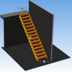
"Automatic lighting of the stairs at night"
1) Assemble the control circuit
2) Make a printed circuit board and case
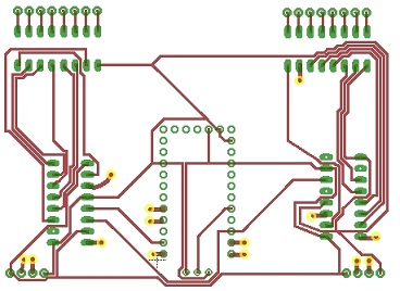
I learned how to design quickly, I tried many CAD programs, EAGLE turned out to be the most convenient. And one of the ways of making was explained and demonstrated by a friend who is fond of this topic. FILES (brd, sch)
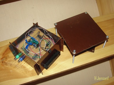
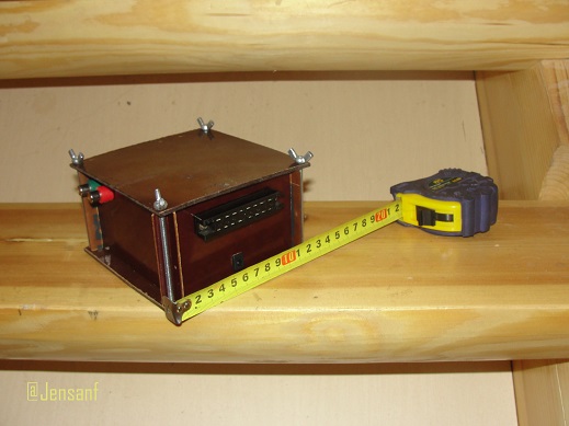
The entire device is made with a separate unit with connectors, so that in case of a breakdown or upgrade, you can change the control module or the working body.
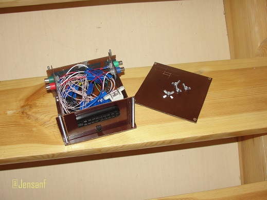
')
A box made from getinaksa. The connectors are torn off unnecessary devices and glued to cold welding.
3) Write a program
4) Make installation on the stairs
The most time-consuming and tedious stage of work , it was necessary to lay a 40m cable and solder about 80 conductors.
Control equipment placed under the stairs.

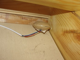
The wires are removed in the cable channels.
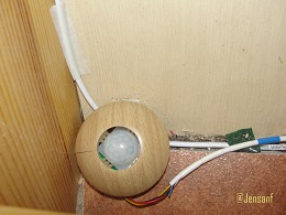
The sensors are hidden under the first steps above and below, their placement was experimentally, the main task is to limit the viewing angle so as not to include the stairs in vain.
The phototransistor is installed in the center of the staircase, where the light is the worst, so the staircase works perfectly even in cloudy weather.
LED strips are glued on the back sides of the steps so as not to hit the eyes when climbing up. Since the tapes were of different companies and IP, I had to alternate them across the step, which was even original.
It took 3 days to complete the installation of all the equipment, there are still flaws in the design :
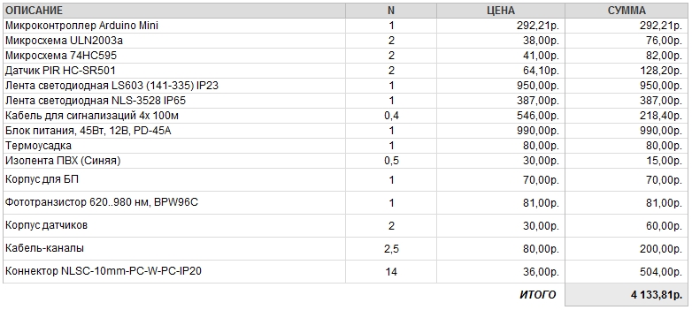
5) Calculate costs
6) Conclusion:
It turned out even better than I imagined. In general, the project can be refined indefinitely, but at the beta-version stage it works stably and reliably.
Naturally, this device does not open America, but certainly COOL, when an idea is born from the head into the world and begins to work. Good luck and inexhaustible creative inspiration to all!
7) If I started a project now, would I do it differently?
First of all, I studied similar projects on the Internet, and found Rimidalw excellent work . After analyzing the experience of others and gaining confidence, I began to implement my project.
Purpose:
"Automatic lighting of the stairs at night"
Tasks:
1) Assemble the control circuit
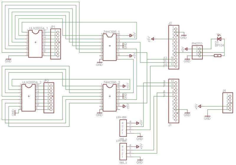
- The brain of the whole structure is the Arduino Mini
- The sensors are two PIR-sensors
- To increase the pins, the 74HC595 chip
- LED strips are controlled by IC ULN2003A
- Light Sensor Phototransistor
- Power supply with two outputs +12 and +5
2) Make a printed circuit board and case
I learned how to design quickly, I tried many CAD programs, EAGLE turned out to be the most convenient. And one of the ways of making was explained and demonstrated by a friend who is fond of this topic. FILES (brd, sch)
The entire device is made with a separate unit with connectors, so that in case of a breakdown or upgrade, you can change the control module or the working body.
')
A box made from getinaksa. The connectors are torn off unnecessary devices and glued to cold welding.
3) Write a program
The code is hidden HERE >>
Since there was no access stairs, I had to experiment on models from micro-bulbs, unfortunately she did not live up to the stage of writing the article.
int DS_Pin = 11; //pin 14 DS/SDI on the 75HC595 int ST_Pin = 8; //pin 12 ST_CP/RCLK on the 75HC595 int SH_Pin = 12; //pin 11 SH_CP/SRCLK on the 75HC595 const int PIR1 = 5;// - const int PIR2 = 6;// - int sensorPin = A0;// // ****** int OverTime =15000; // () const int N=14; //- int Qck_tm = 300; // int Wt_tm = 2000; // int L=30; // // ****** int a1,a2; // long pM=0; // millis() long pM1=0; // millis() long pM10=0; // millis() unsigned int sensorValue = 0; // int registers[N+1]; // boolean b2=false; // boolean b3=false; // void setup(){ pinMode(PIR1, INPUT); pinMode(PIR2, INPUT); pinMode(DS_Pin, OUTPUT); pinMode(ST_Pin, OUTPUT); pinMode(SH_Pin, OUTPUT); Serial.begin(9600); clearRegisters(); writeRegisters(); } // void clearRegisters(){ for(int i = N; i >= 0; i--){ registers[i] = LOW; } } // void writeRegisters(){ digitalWrite(ST_Pin, LOW); for(int i = N; i >= 0; i--){ digitalWrite(SH_Pin, LOW); int val = registers[i]; digitalWrite(DS_Pin, val); digitalWrite(SH_Pin, HIGH); } digitalWrite(ST_Pin, HIGH); } // void setRegister(int index, int value){ registers[index] = value; } // void LightON(boolean a){ b2=true; if(a) for (int k=0;k<=N;) { a1=digitalRead(PIR1); if ( a1==HIGH && millis() - pM1 > 1000) { pM1 = millis(); } if (millis() - pM > Qck_tm) { pM = millis(); setRegister(k, HIGH); writeRegisters(); k++; } } else for (int k=N;k>=0;) { a2=digitalRead(PIR2); if ( a2 == HIGH && millis() - pM1 > 1000) { pM1 = millis(); } if (millis() - pM > Qck_tm) { pM = millis(); setRegister(k, HIGH); writeRegisters(); k--; } } } // void LightOFF(boolean a){ b2=false; if(a){ int k=0; while(k<=N) { a1=digitalRead(PIR1); if (a1== HIGH){ LightON(true); break; } if (millis() - pM > Qck_tm){ pM = millis(); setRegister(k, LOW); writeRegisters(); k++; }}} else { int k=N; while(k>=0) { a2=digitalRead(PIR2); if (a2 == HIGH){ LightON(false); break; } if (millis() - pM > Qck_tm){ pM = millis(); setRegister(k, LOW); writeRegisters(); k--; }}} } void loop(){ sensorValue = analogRead(sensorPin); // Serial.println(sensorValue, DEC); if (sensorValue < L){ a1=digitalRead(PIR1); if ( a1 == HIGH && a2== LOW)// { pM=millis(); LightON(true); while (b2) { a2=digitalRead(PIR2); if (a2 == HIGH && millis() - pM10 > 1000 || (millis() - pM > OverTime)) { pM10 = millis(); LightOFF(true); }}} a2=digitalRead(PIR2); if (a2 == HIGH && a1 == LOW) { pM=millis(); LightON(false); while (b2) { a1=digitalRead(PIR1); if (a1== HIGH && millis() - pM10 > 1000 || (millis() - pM > OverTime)) { pM10 = millis(); LightOFF(false); }}}}} Since there was no access stairs, I had to experiment on models from micro-bulbs, unfortunately she did not live up to the stage of writing the article.
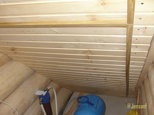
4) Make installation on the stairs
The most time-consuming and tedious stage of work , it was necessary to lay a 40m cable and solder about 80 conductors.
Control equipment placed under the stairs.
The wires are removed in the cable channels.
The sensors are hidden under the first steps above and below, their placement was experimentally, the main task is to limit the viewing angle so as not to include the stairs in vain.
The phototransistor is installed in the center of the staircase, where the light is the worst, so the staircase works perfectly even in cloudy weather.
LED strips are glued on the back sides of the steps so as not to hit the eyes when climbing up. Since the tapes were of different companies and IP, I had to alternate them across the step, which was even original.
It took 3 days to complete the installation of all the equipment, there are still flaws in the design :
- The sensors are glued to double-sided tape, I want to secure them more reliably.
- Better disguise the conductors under the steps
- Move power and control units to close them with a curtain
5) Calculate costs
***VIDEO***
6) Conclusion:
It turned out even better than I imagined. In general, the project can be refined indefinitely, but at the beta-version stage it works stably and reliably.
Naturally, this device does not open America, but certainly COOL, when an idea is born from the head into the world and begins to work. Good luck and inexhaustible creative inspiration to all!
7) If I started a project now, would I do it differently?
- The connectors should be installed on the board, the device will become more compact, and the soldering will be two times smaller.
- The ULN2003A chip is replaced with a normal LED driver, or with a transistor chip, so that the PWM (smooth start) feature can appear.
- To use a less sophisticated power supply , the usual LED for 12V is quite suitable. Arduino feed through stabilizer at 5V.
- And, of course, ideally, use four sensors , or two range finders along the stairs to accurately determine the number of people and their behavior on the stairs.
Source: https://habr.com/ru/post/181336/
All Articles