Making radio control for the aircraft
After reading this post I caught fire and I had the idea to rivet my airplane. He took the finished drawings , ordered the Chinese motors, batteries and propellers. But radio control decided to do it yourself, firstly - it is more interesting, and secondly - you have to take something with yourself while the parcel with the other parts will go, well, and thirdly - there is an opportunity to originate and add all sorts of buns.
Careful, pictures!
How and what to manage
Normal people take the receiver, stick servos into it, adjust the speed control, move the levers on the console and enjoy life without asking how they work and without going into details. In our case, this will not work. The first task was to find out how the servos are controlled. Everything turns out to be quite simple, the drive has three wires: + power, - power and signal. On the signal wire of the rectangular pulses of variable duty cycle. To understand what it is we look at the picture:
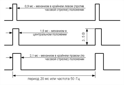
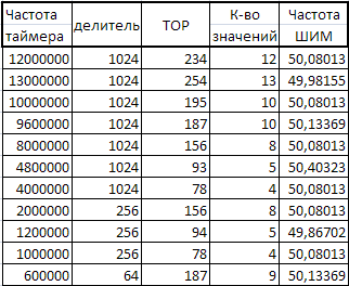
So, if we want to set the drive to the extreme left position, we need to send pulses with a duration of 0.9 ms with an interval of 20 ms, if to the far right - a duration of 2.1 ms, the interval is the same, well, with average positions, the same. As it turned out, the speed controllers are controlled in a similar way. Those who are in the subject will say that this is a normal PWM , which is implemented on any microcontroller - a trifling matter. So I decided so, I bought a servo at a local store and riveted on it a so-called servo tester on ATtiny13. And it turned out that PWM is not quite simple, but with pitfalls. As can be seen from the above diagram, the duty cycle (the ratio of the pulse duration to the period duration) is from 5% to 10% (later I take the pulses of 1.0 ms and 2.0 ms for the extreme positions) for the 256-digit PWM counter ATtiny13 this corresponds to values from 25 to 50. But this is assuming that it takes 20ms to fill the counter, but in fact it will not work and for the frequency 9.6 MHz and the prescaler 1024 it is necessary to limit the counter to 187 (TOR), in which case we will have a frequency of 50.134 Hz. In most (if not all) servos, there is no accurate reference frequency generator and therefore the frequency of the control signal may float a little. If you leave the TOR of the 255 counter, then the frequency of the control signal will be 36.76 Hz - on some drives it will work (possibly with glitches), but not at all. So, now we have a 187-digit counter, for it 5-10% correspond to values from 10 to 20 - only 10 values, it will work out a bit discretely. If you are thinking of playing with the clock frequency and the prescaler below, I quote a comparative tablet for 8-bit PWM:
But after all, most microcontrollers have a 16-bit (and more) timer for generating PWM. Here, the problem with discreteness disappears immediately and the frequency can be precisely set. For a long time I will not paint, I immediately give a sign:

')
I do not think that for the Chinese servos there is a significant difference of 600 and 1200 values, so the issue with positioning accuracy can be considered closed.
Multichannel control
With one servos figured out, but for the aircraft they need at least three and another speed controller. The solution to the forehead is to take a microcontroller with four channels of 16-bit PWM, but such a controller will be expensive and most likely take a lot of space on the board. The second option is to cut software PWM, but taking CPU time is not an option either. If you look at the signal diagrams again, then 80% of the time it does not carry any information, so it would be more rational to set the impulse itself to 1-2 ms for PWM. Why does the porosity vary within such narrow limits, because it would be easier to form and read pulses with a porosity of at least 10-90%? Why do you need that uninformative piece of the signal that takes 80% of the time? I suspected that perhaps these 80% might take impulses for other actuators, and then this signal is divided into several different ones. That is, in a period of 20ms, 10 pulses of 1-2ms duration can fit, then this signal is somehow divided into 10 different pulses with a duration of just 20ms for some demultiplexer. No sooner said than done, I drew such a scheme in PROTEUS:
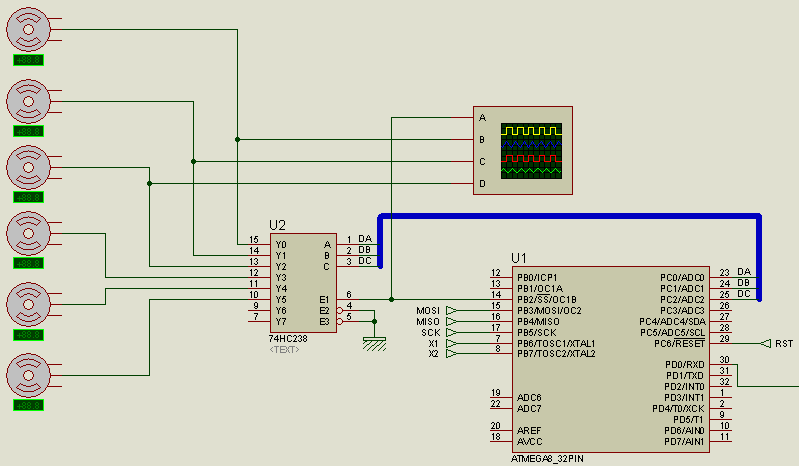
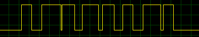
In the role of the demultiplexer - 74HC238, to its input E, pulses are output from the output of the microcontroller. These pulses are PWM with a period of 2ms (500Hz) and a duty cycle of 50-100%. Each pulse has its own duty cycle, indicating the state of each channel. Here is the signal at the input E:
In order for 74HC238 to know which output to feed the current signal, we use the PORTC microcontroller and the inputs A, B, C of the demultiplexer. As a result, the outputs we get the following signals:

The output signals are the correct frequency (50Hz) and duty cycle (5-10%). So, you need to generate a PWM frequency of 500 Hz and a filling of 50-100%, here is a label for setting the prescaler and the TOR of a 16-bit counter:
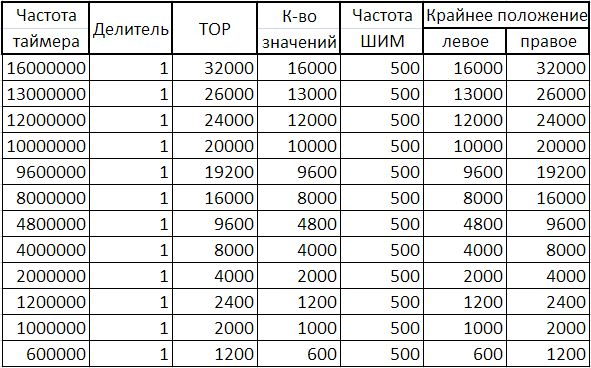
Interestingly, the possible number of PWM values is exactly 1000 times lower than the frequency of the timer.
Software implementation
For ATmega8 with a clock frequency of 16 MHz in AtmelStudio6 everything is implemented as follows: first, define the counter values for the extreme positions of the servos:
#define LOW 16000U #define HIGH 32000U Then we initialize the PWM generator on the timer / counter1:
OCR1A = HIGH; // TCCR1A = 0<<COM1A1 | 0<<COM1A0 | 1<<COM1B1 | 0<<COM1B0 | 0<<FOC1A | 0<<FOC1B | 1<<WGM11 | 1<<WGM10; // Fast PWM OC1B , OCR1A TCCR1B = 0<<ICNC1 | 0<<ICES1 | 1<<WGM13 | 1<<WGM12 | 0<<CS12 | 0<<CS11 | 1<<CS10; // 1 TIMSK = 1<<OCIE1A | 1<<OCIE1B | 0<<TOIE1; // It remains to implement interrupts:
ISR(TIMER1_COMPA_vect) // , { //c_num- , , channels - if (c_num <= 7) { OCR1B = channels[c_num]; } else { OCR1B = 0; // 8 9 } } ISR(TIMER1_COMPB_vect, ISR_NOBLOCK)// { if (c_num <= 7) { PORTC = c_num; // 0-7 PORTC } // 0 9 if (c_num >= 9) { c_num = 0; } else { c_num++; } } Globally enable interrupts and is done by stuffing the channels values from LOW to HIGH to channels by changing values.
Implementation in the gland
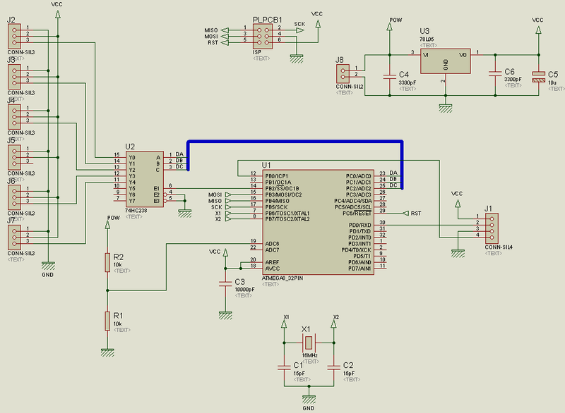
Well, with the theory figured out, it's time to implement it all. The ATmega8A microcontroller is selected as the brain of the system, clocked from quartz at 16 MHz (not because I wanted 16,000 servo positions, but because I had such rolls). The control signal for the MC will come through the UART. The result is such a schema:
After some time, this shawl appeared:
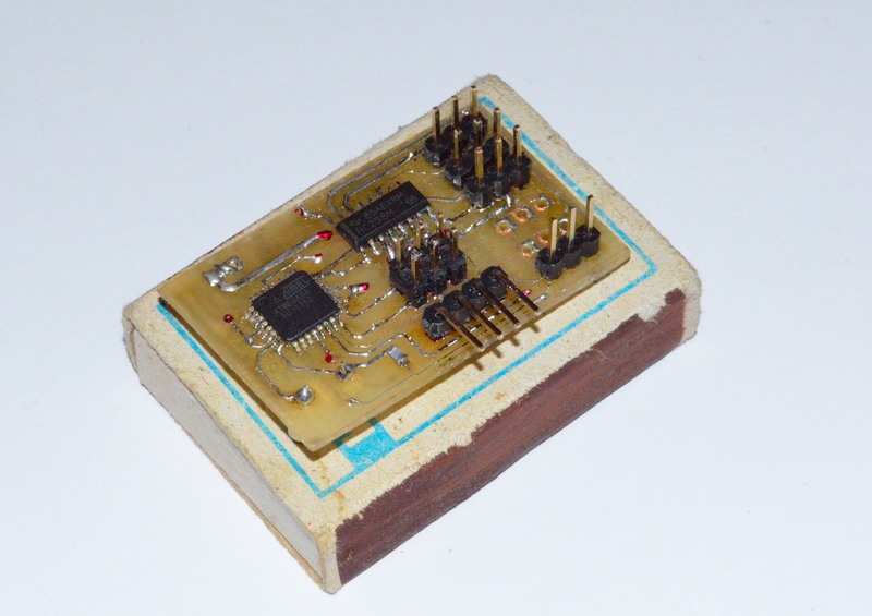

I didn’t solder two three-pin connectors because I don’t need them, but they are not soldered in a row because I don’t have any metallization of holes, and I could replace the tracks in the lower connector from two sides with a wire, but I don’t have a software problem to output a signal to any connector . Also there is no 78L05 because in my engine controller there is an in-built stabilizer (WEIGHT).
To receive data, the HM-R868 radio module is connected to the board:
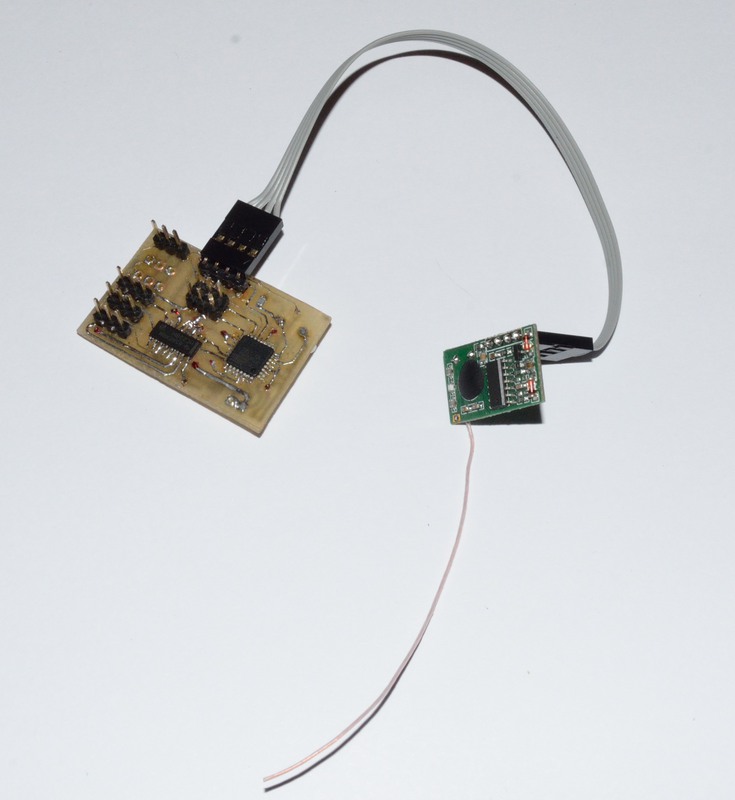
Initially I thought to stick it directly into the board, but this design did not fit into the airplane, I had to do it through a loop. If you change the firmware, the contacts of the programming connector can be used to turn on / off any systems (side lights, etc.)
The fee cost about 20 UAH = $ 2.50, the receiver - 30 UAH = $ 3.75.
Transmitting part
The aircraft part is there, it remains to deal with ground equipment. As it was written earlier, data is transmitted via UART, one byte per channel. Initially, I connected my system with a wire through an adapter to a computer and sent commands via a terminal. In order for the decoder to determine the beginning of the parcel, and in the future, allocate the parcels addressed to him, first the byte identifier is sent, then 8 bytes of the channels determining the state. Later he began to use radio modules, when the transmitter was turned off, all the motors began to twitch wildly. In order to filter out the signal from the noise, the tenth byte sends the XOR of all 9 previous bytes. It helped, but weakly, added another check for a timeout between bytes, if it is exceeded - the whole package is ignored and the reception begins anew, by waiting for the byte-identifier. With the addition of the checksum in the form of XOR, sending commands from the terminal became stressful, so I quickly riveted this program with sliders:

The number in the lower left corner is the checksum. By moving the sliders on the computer, the rudders on the plane were moving! In general, I debugged all this and began to think about the remote control, I bought these joysticks for it:

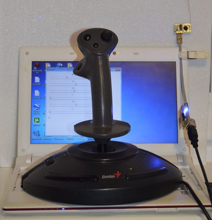
But then a thought came to me. At one time, I dragged myself from all kinds of flight simulators: “Il-2 Sturmovik”, “Lock On”, “MSFSX”, “Ka-50 Black Shark” and others. Accordingly, I had a Genius F-23 joystick and I decided to fasten it to above prog with sliders. Googled how to implement it, found this post and it turned out! To control the airplane with the help of a full-fledged joystick, it seems to me, much cooler than a small stick on the remote. In general, everything together is shown on the first photo - this is a netbook, joystick, converter on the FT232, and the HM-T868 transmitter connected to it. The converter is connected with a 2m cable from the printer, which allows you to fix it on some tree or something like that.
Start!
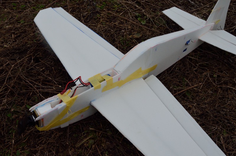
So, there is a plane, there is a radio control - Let's go! (C) The first flight was made over the asphalt, the result is a fuselage broken in half and a half-dug out engine. The second flight was made over a softer surface:
The subsequent flights of 10 were also not particularly successful. I think the main reason is the strong discreteness of the joystick - by the roll it gave only 16 values (instead of the possible 256), with the pitch axis it is not better. But as a result of the tests, the aircraft was significantly damaged and beyond repair:
- check the veracity of this version is not yet possible. The attempt to level the aircraft, recorded on video, speaks in favor of this version - it flies inclined, and then abruptly collapses in the opposite direction (and should smoothly). Here is a more visual video:
The range of the equipment - about 80m, then also catches further, but through time.
Well, that's all, thank you for your attention. I hope this information will be useful for someone. I will be glad to answer all the questions.
The archive scheme and layout of the board for Proteus.
Source: https://habr.com/ru/post/180759/
All Articles