Low automation, or how to send two bytes
Something about me
I do industrial automation. Literally from head to ass, i.e. from the field level (sensors / actuators) to the top (PLC programming / SCADA development). It so happened that most of all I was doing the setup, but the last year was mostly development. In addition, for me, software and hardware are divided into Siemens and everything else.
about the project
The essence of the project is to update the automation systems at a fairly large number of pumping stations (water and sewage). In addition to the update itself, the task was to collect and transmit the current values of a number of parameters to a common control room for centralized archiving and monitoring. Geographically, all this economy is located in the Lower Galilee, in Israel.
At the time of the start of work, automation tools at different stations were a very diverse zoo: from ET-200S CPU controllers at more recent stations to relay logic for older ones. Currently, Siemens, Twido (Schneider), Koyo, GE Fanuc controllers are working at different stations.
It turned out that this project is formally implemented by Schneider Electric, our company is a subcontractor. This determined the choice of SCADA for control room (Vijeo Citect) and controllers for stations where their replacement is required.
Features and Difficulties
And there are not so many of them. The main and almost the only one is how to transfer technological information from stations that are sufficiently distant from each other to the control center. For this purpose, a system from Realiteq was used. The idea is quite simple: the company sells its devices (Motorola internals), which have a ModBus interface (it is possible to use RS-232, 485, Ethernet), a cellular terminal and are configured using a special utility. Further, these terminals receive Modbus data and transmit their server to the company. For this, the company takes a monthly fee, the exact size of which is unknown to me. To get this data and use it in SCADA, you need to install another utility, the OPC server, which requests data from the company’s server via the Internet and sends it via the OPC protocol.
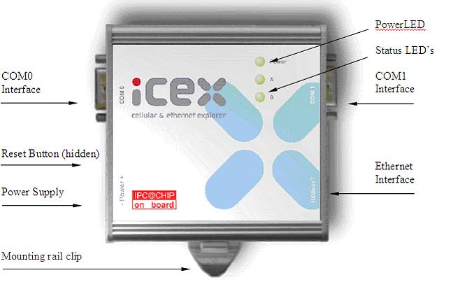
The configuration stored in the module itself is minimal. This is the project name, the node name in the project (there may be several nodes), settings for connecting to the controller and setting up the cellular terminal.
Here is the terminal itself:
')
All data settings exchanged by the terminal in the PLC are made through the web interface or through a special utility. "Access to the body" is no longer required, only the Internet is needed. This is the web interface:
In addition to data collection, the web interface has minimal SCADA functionality, i.e. You can implement the simplest pictures.
And this is how the water station looks on the operator’s screen in the Citect system:
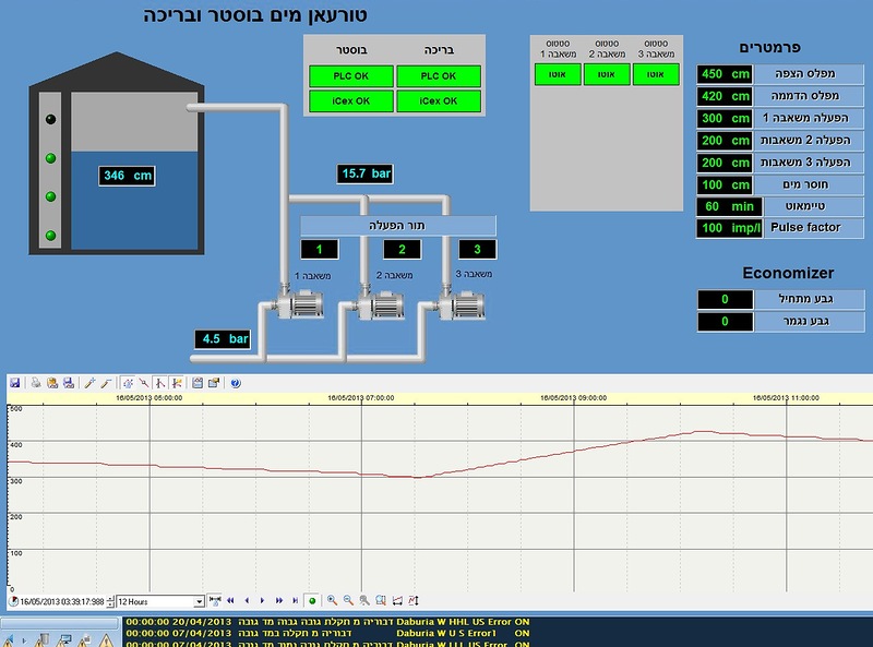
Naturally, all the Hebrew inscriptions do not forget where the project is located :) In a nutshell, on this screen we see the water level in the tank, the status of the float level sensors (top, bottom and two intermediate ones on the left on the tank), the state of all three pumps (gray - off, green - in operation, red - malfunction), turn-on sequence (number in the box above each pump), water pressure at the inlet and outlet of the pumping station, level setpoints (full / empty capacity alarm, level of pump shutdown, first level pump, the level of inclusion of the backup pump). Below is a graph of the level change in the last 12 hours; the story is stored for 3 years
Additional difficulties with water stations
In general, the algorithm of the water pumping station operation is almost the same as that of the sewage plant: turn on the pump at one level in the tank, turn off the pump at another level. The difference lies in the fact that at the sewer station capacity and pumps are in the same place, and at the water-pressure station - far enough from each other. Strictly speaking, due to the remoteness of the pumping and expendable capacity - these are two different stations, each with its own controller.
The need for pressure stations is due to the fact that some localities are located on the slopes of the mountains, and the pressure in the central water supply system is insufficient to raise the water to the desired height. Therefore, on the uplands, consumable tanks were built (the principle is similar to water towers), and below - pumping tanks, which raise the pressure and fill these tanks as needed.
Let's return to our project. This territorial remoteness also creates the main complexity. The capacity together with the level sensor is located too far from the pump room and at various times attempts were made to ensure communication over the radio channel, but at the time of the implementation of our project this system did not work for reasons unknown to me.
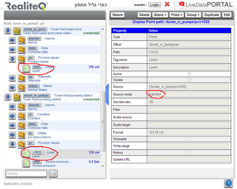
But the data collection system that we use allows us not only to receive data, but also to transfer them between different stations within the project. Thus, the controller's tasks on the consumable capacity are minimal: to receive a signal from the level sensor (4..20 mA), convert it to engineering units and transfer it up to the pumping unit using the Modbus protocol. This Modbus register is the very 2 bytes in the header, without which the pumping station cannot operate. In the first screenshot, I circled in red the source register and the register-receiver in the second controller.
In fact, this controller transmits a little more information. During operation, it is possible that at the pump we see: the level has decreased, it is time to fill the tank. And turn on the pump. The pump is running, the tank is filling up, and at some point the connection is lost. The level in the tank grows, and the pump controller does not receive information. And the capacity overflows.
To prevent this, we transfer one more value from the tank to the pump room. This is a counter whose value increases every minute. Just once a minute, the pump controller saves the resulting value and compares it with the previous four. If they all match, it means that already 5 minutes we have a loss of communication.
At the pump room, at each pump start-up, a timer starts at the same time as they, the setpoint of which can be changed. If the timer has finished counting and the controller “sees” the loss of communication - the pumps stop. Thus implemented protection.
The status of the project today
In total, the project is scheduled to update the automation and connect 12 stations to the control room. Currently, 8 of them are finished, the hardware has been updated as necessary, if necessary, changes have been made to the controller programs and information is regularly received at the dispatch console.
And, for dessert, a general view of the village, where the pumping and expendable capacity are located:

Source: https://habr.com/ru/post/180273/
All Articles