Sphere from two triangles
 The story of this demo is this: once a friend of mine made a map generator for his game of planets and wanted the maps created in this way to be shown as a rotating sphere. However, at the same time, he did not want to use 3D graphics, but instead generated a lot of frames with this very sphere, which was rotated at different angles. The amount of memory used was ... let's say, redundant, well, and the speed of frame generation (as well as the quality of their execution) suffered greatly. A little thought, I was able to help him optimize this process, but in general I had a fair feeling that this was a task for OpenGL, and not for 2D graphics at all.
And so, once, when insomnia tormented me, I decided to try to combine these two approaches: draw a rotating sphere (with a map of the planet stretched on it) through OpenGL, but at the same time leaving it flat.
And I must say that I did it. But first things first.
Process math
To begin with, we will define our own task. For each point on the screen, we have two screen coordinates in the Cartesian coordinate system, and we need to find for it spherical coordinates (in fact, latitude and longitude), which in fact are the texture coordinates for the map of the planet.
')
So. The transition from a spherical coordinate system to a Cartesian one is given by a system of equations (taken from Wikipedia ):
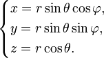
and the reverse transition - such equations:
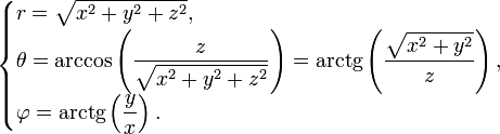
We can easily get the Z coordinate from X and Y , knowing the radius, and we can take the radius to be one.
In the future, we will agree that we will slightly change the above equations by swapping the concepts of Y (we will have a screen vertical) and Z (this will be the depth of the scene).
Technical part
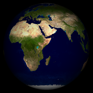
The implementation of the idea will require us to use quad (I already wrote about how to use it, so I will not repeat, especially since the link to the full source code of the project is given below), as well as two textures: the actual map of the planet (I used the texture of Earth 2048x1024) and texture coordinates maps. The code for generating the second texture accurately repeats the math conversion from Cartesian coordinates to spherical:
int texSize = 1024; double r = texSize * 0.5; int[] pixels = new int[texSize * texSize]; for (int row = 0, idx = 0; row < texSize; row++) { double y = (r - row) / r; double sin_theta = Math.sqrt(1 - y*y); double theta = Math.acos(y); long v = Math.round(255 * theta / Math.PI); for (int col = 0; col < texSize; col++) { double x = (r - col) / r; long u = 0, a = 0; if (x >= -sin_theta && x <= sin_theta) { double z = Math.sqrt(1 - y*y - x*x); double phi = Math.atan2(z, x); u = Math.round(255 * phi / (2 * Math.PI)); a = Math.round(255 * z); } pixels[idx++] = (int) ((a << 24) + (v << 8) + u); } } GLES20.glGenTextures(1, genbuf, 0); offsetTex = genbuf[0]; if (offsetTex != 0) { GLES20.glBindTexture(GLES20.GL_TEXTURE_2D, offsetTex); GLES20.glTexParameteri(GLES20.GL_TEXTURE_2D, GLES20.GL_TEXTURE_MIN_FILTER, GLES20.GL_NEAREST); GLES20.glTexParameteri(GLES20.GL_TEXTURE_2D, GLES20.GL_TEXTURE_MAG_FILTER, GLES20.GL_NEAREST); GLES20.glTexParameteri(GLES20.GL_TEXTURE_2D, GLES20.GL_TEXTURE_WRAP_S, GLES20.GL_NONE); GLES20.glTexParameteri(GLES20.GL_TEXTURE_2D, GLES20.GL_TEXTURE_WRAP_T, GLES20.GL_NONE); GLES20.glTexImage2D(GLES20.GL_TEXTURE_2D, 0, GLES20.GL_RGBA, texSize, texSize, 0, GLES20.GL_RGBA, GLES20.GL_UNSIGNED_BYTE, IntBuffer.wrap(pixels)); } Note that the X and Y coordinates are moved from the range [0..texSize] to the range [-1..1], and the texture coordinates U and V are transferred from the radians to the range [0..255], and then written down in red and the green components of a 32-bit texture. The alpha channel is used to preserve the “depth” ( Z coordinates), while the blue remains unused. Disabling bilinear filtering is also not accidental: at this stage, it does not give any effect (neighboring points have the same values anyway, with rather sharp jumps), but in what I'm going to show next, it will be is harmful. But more on that below.
 Both textures are fed to the input of a simple pixel shader (hereinafter, the images are clickable):
 private final String quadFS = "precision mediump float;\n" + "uniform sampler2D uTexture0;\n" + "uniform sampler2D uTexture1;\n" + "varying vec4 TexCoord0;\n" + "void main() {\n" + " vec4 vTex = texture2D(uTexture0, TexCoord0.xy);\n" + " vec3 vCol = texture2D(uTexture1, vTex.xy).rgb;\n" + " gl_FragColor = vec4(vCol, (vTex.w > 0.0 ? 1.0 : 0.0));\n" + "}\n"; The scene rendering code I do not cite, because everything is quite trivial in it (and, again, it can be viewed in its full source), and the shader itself is rather primitive. The most curious thing in it, perhaps, is that the alpha channel is only being tested for positivity, whereas it would be possible to use it for the lighting effect.
It turned out pretty well, but somehow flat, plus I would like to add the actual rotation of the planet around its axis.
 We include one more parameter in the shader (we will change it depending on the time in the range [0..1]), plus add “depth” (multiply the color by the value from the alpha channel):
 private final String quadFS = "precision mediump float;\n" + "uniform sampler2D uTexture0;\n" + "uniform sampler2D uTexture1;\n" + "uniform float uOffset;\n" + "varying vec4 TexCoord0;\n" + "void main() {\n" + " vec4 vTex = texture2D(uTexture0, TexCoord0.xy);\n" + " vTex.x += uOffset;\n" + " vec3 vCol = texture2D(uTexture1, vTex.xy).rgb;\n" + " gl_FragColor = vec4(vCol * vTex.w, (vTex.w > 0.0 ? 1.0 : 0.0));\n" + "}\n"; Well, there are no complaints to the sphere itself, but the picture looks somehow ... eight-bit or something. And no wonder: we wrote texture coordinates in the range [0..255] (the maximum available to us in normal color components), which means our texture can be no more than 256 points in height (and 512 in width, taking into account the rotation). Not enough, you need at least 10-bit precision.
Increase resolution
Immediately I warn you: the code described here can work crookedly on any devices, although I managed to achieve normal rendering on all devices that I could hold in my hands. In any case, the one described here is the usual hack.
So, we still have two of the three color components, i.e. 16 bits out of 24. Well, let's pack the data in such a way that each texture coordinate has a size of 12 bits, which allows us to work with textures up to 4096 pixels in height! To do this, change literally three lines in the program:
... long v = Math.round(4095 * theta / Math.PI); ... u = Math.round(4095 * phi / (2 * Math.PI)); ... pixels[idx++] = (int) ((a << 24) + (v << 12) + ((u & 15) << 8) + (u >> 4)); ... and write a new shader that takes into account the 12-bit addressing scheme (it is in this place that bilinear filtering is disabled!):

private final String quadFS = "precision mediump float;\n" + "uniform sampler2D uTexture0;\n" + "uniform sampler2D uTexture1;\n" + "uniform float uOffset;\n" + "varying vec4 TexCoord0;\n" + "void main() {\n" + " vec4 vTex = texture2D(uTexture0, TexCoord0.xy);\n" + " vec3 vOff = vTex.xyz * 255.0 + vec3(0.5, 0.5, 0.5);\n" + " float hiY = floor(vOff.y / 16.0);\n" + " float loY = vOff.y - 16.0 * hiY;\n" + " vec2 vCoord = vec2(\n" + " (vOff.x * 16.0 + loY) / 4095.0 + uOffset,\n" + " (vOff.z * 16.0 + hiY) / 4095.0);\n" + " vec3 vCol = texture2D(uTexture1, vCoord).rgb;\n" + " gl_FragColor = vec4(vCol * vTex.w, (vTex.w > 0.0 ? 1.0 : 0.0));\n" + "}\n"; Well, it's a completely different thing! With minor changes (adding scaling by pinching and rotating with a finger), I showed this program to my friends and colleagues, and at the same time asked how many, in their opinion, there are triangles in this scene. The results varied, and the question itself was suspicious of a trick (in this case, the respondents joked "one", which was not far from the truth), but the correct answer was consistently surprising. And all, as one, they asked: why can the sphere be twisted around one axis, but not tilted? .. Hmm.
Incline
And the fact is that the slope in this scheme is much more difficult to implement. In fact, the task is not intractable, and I even coped with it, but it was not without nuances.
In essence, the task is to take the offset coordinate V , whereas the U coordinate does not change: this is because we add rotation around the X axis. The plan is as follows: convert the texture coordinates to screen ones (in the range [-1..1]), apply the rotation matrix around the horizontal axis to them (for this we write the sine and cosine of the tilt angle to the new uTilt constant), and then use the new Y coordinate for sampling in our patterned texture. The “rotated” Z coordinate is also useful to us, with its help we will mirror the longitude for the back side of the ball). The screen coordinate Z will have to be calculated explicitly, in order not to make two texture samples from one texture, at the same time this will increase its accuracy.

private final String quadFS = "precision mediump float;\n" + "uniform sampler2D uTexture0;\n" + "uniform sampler2D uTexture1;\n" + "uniform float uOffset;\n" + "uniform vec2 uTilt;\n" + "varying vec4 TexCoord0;\n" + "void main() {\n" + " float sx = 2.0 * TexCoord0.x - 1.0;\n" + " float sy = 2.0 * TexCoord0.y - 1.0;\n" + " float z2 = 1.0 - sx * sx - sy * sy;\n" + " if (z2 > 0.0) {;\n" + " float sz = sqrt(z2);\n" + " float y = (sy * uTilt.y - sz * uTilt.x + 1.0) * 0.5;\n" + " float z = (sy * uTilt.x + sz * uTilt.y);\n" + " vec4 vTex = texture2D(uTexture0, vec2(TexCoord0.x, y));\n" + " vec3 vOff = vTex.xyz * 255.0 + vec3(0.5, 0.5, 0.5);\n" + " float hiY = floor(vOff.y / 16.0);\n" + " float loY = vOff.y - 16.0 * hiY;\n" + " vec2 vCoord = vec2(\n" + " (vOff.x * 16.0 + loY) / 4095.0,\n" + " (vOff.z * 16.0 + hiY) / 4095.0);\n" + " if (z < 0.0) { vCoord.x = 1.0 - vCoord.x; }\n" + " vCoord.x += uOffset;\n" + " vec3 vCol = texture2D(uTexture1, vCoord).rgb;\n" + " gl_FragColor = vec4(vCol * sz, 1.0);\n" + " } else {\n" + " gl_FragColor = vec4(0.0, 0.0, 0.0, 0.0);\n" + " }\n" + "}\n"; Hooray, the slope was a success! That's just a strange noise on the border of the hemispheres a little confused. Obviously, the problem lies in the lack of accuracy of addressing at the boundary points (the points on the circle itself correspond to a too large range of coordinates, one texel spreads out to a rather noticeable interval). In the end, I managed to defeat it using two generated textures instead of one.
As a result, you can zoom in and turn the ball almost the same as in Google Earth. With the difference that here - only two triangles.
And finally, the promised. The source code for the project is available on GitHub .
You can also download the finished .apk file .
By the way, the source for my past posts are available there .
Update: It seems that I still managed to achieve accurate texturing on all devices, it required a bit to change the order of bits, and also slightly correct the rounding of the colors of the template texture. Now even forcibly compressed textures should work more or less normally. The code on GitHub is updated, new .apk-files are uploaded.
Update 2: Still, the artifact on the border of the hemispheres was defeated. Sources and ready .apk updated.
In addition, I added another bonus: the WebGL version of this demo is available here .
Source: https://habr.com/ru/post/180245/
All Articles