A little more about SDH and PDH
After listening to the second release of the LinkMiAp podcast published on habrahabr.ru , I had a desire to supplement and correct a little what was said in the first part of the issue devoted to SDH / PDH. But since all my thoughts did not fit into the framework of the usual commentary, I used the May holidays to write this post.
The Kotelnikov theorem (the Nyquist – Shannon theorem) answers the question: - How often do you need to take readings from an analog signal in order to be able to restore it according to these indications?
An analog signal has such a property as a spectrum (the frequency range in which the signal is located), for example, a medium-statistical person hears sound in the range from 20 Hz to 20 kHz. In order to digitize the entire audible spectrum of human sounds without loss, according to Kotelnikov's theorem, the signal level should be measured with a frequency twice as high as the upper frequency of the spectrum , that is, 40 kHz. It is natural to digitize the entire audible spectrum - great luxury,
')
Even in the era of analog systems with frequency multiplexing of channels, it turned out that in order to maintain speech intelligibility, it is enough to leave the range from 300 Hz to 3400 Hz (standard PM channel ) from the audio signal. Moreover, the spectrum can be cut even more, but although a person will be able to understand the speech, it will no longer be possible to recognize the speaker’s voice. Thus, the developers of systems with frequency multiplexing of channels spread channels in frequency, allocating a 4 kHz band to each channel to provide a guard interval between channels. So, the first channel in K-60 systems was located in the range of 252-248 kHz, the second channel in the range of 248-244 kHz, and so on, up to 12 kHz. Modern DWDM systems work on the same principle, but with an optical signal.
Developers of digital systems also decided to use channels with a width of 4 kHz for compatibility with the analog compression systems existing at that time. Well, according to Kotelnikov's theorem, such a signal must be read at a frequency of 8 kHz.
The signal level is encoded by an eight-bit code, and quantization does not occur evenly, and the smaller the level, the more accurately the signal is measured, since the human ear can better distinguish the same difference between two small levels than between two large ones.
To betray 8 bits with a frequency of 8000 Hz, a speed of 8000x8 = 64000 bps is needed - this will be the Main Digital Channel (BCC) . 32 such channels form the E1 stream.
In addition to E1, it is rather difficult to meet other levels of the pleo-ohron hierarchy in Russia today. The exception may be sometimes encountered optical modems on four or eight E1 streams that they have inside, E2 or STM-1, I do not know. But these modems, as a rule, are installed in pairs and work with each other without configuration requiring high knowledge.
If we present the transmission system as a kind of conveyor, on which at one end one worker puts the boxes with books, and at the other end the second worker removes these boxes. So in order for there to be no congestion or downtime, these workers must work synchronously, that is, remove and install the boxes at the same speed, and this requirement is fulfilled in PDH systems. But the authorities decided to increase the productivity of the conveyor and increased its speed four times, this does not affect the work of these two workers, since the boxes from the conveyor should be removed at the same speed with which they are put there, but now there is room on the conveyor. And the authorities put three more workers at the beginning of the conveyor and three at the end. Each of the four workers at the loading should work synchronously with their partner at unloading, and again with this there is no problem. But besides this, the workers during the loading should not interfere with each other, they should put the boxes at the same speed, that is, synchronously and that's the problem with the PDH systems. This problem is solved by allocating additional space on the conveyor, the conveyor moves a little faster than necessary, and each worker has the opportunity to work on loading, without much adjusting to the rest of the workers exposing the boxes to the conveyor.
As a result, it is impossible to snatch one book out of the box in the middle of the conveyor or put the book in the box to a specific place, since it is impossible to determine where this place is at a particular moment in time, eight more workers need to be installed so that they remove the box, remove the book from one of them put this book on an empty seat, and then returned boxes to the place.
Another problem of PDH systems was the incompatibility of hierarchies developed in the USA, Japan, and Europe. But when developing the next generation of systems (SDH), we managed to get rid of these shortcomings, and how to be led increased speed.
In addition to the zero time slot (T0), there is another service channel in the cycle, usually it is located on the 16th place (T16), a little less often on the last 31st channel (T31), some equipment allows you to put it in general at any place, for example SHDSL can cut the cycle (reduce the transmission rate, reducing the number of time slots transmitted) depending on the cable parameters and in order not to cut the service time slot, it is transferred to the beginning of the cycle. This time slot slots the “Control and Interaction Signals” (WMS), more simply the service information is exchanged between the PBX (DSS1, OKS7, etc.), as well as some manufacturers use this channel for remote monitoring of PDH multiplexers.
How multiframe synchronization works is best explained by the example of the 2VSK signaling (2 Dedicated Signal Channels), for the time being it is rather outdated and it is rather difficult to find it in real life, but it is rather simple.
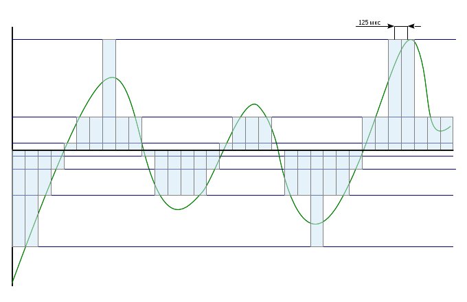
16 cycles (frames) in a row form a superframe (multi frame).
In the 16th time slot of the 1st cycle (not zero) in the first four bits, the signaling information is transmitted (channel seizure, hang up, dialing) for the 1st cycle slot slot. In the second four bits of the signal information for the 17th time slot.
In the 16th time slot of the 2nd cycle, in the first four bits, the signal information for the 2nd time slot of the cycle is transmitted, in the second four bits, the signal information for the 18th time slot, and so on.

The picture shows the 10th superframe cycle, so bits B0-B3 contain signal information for the 10th time slot, and bits B4-B7 for the 26th time slot.
The 16th time slot of the 0th cycle contains information to provide frame-synchronization, similar to how information on frame synchronization is transmitted to T0.
When an IP network runs on top of an E1 stream, IP packet headers are not transferred to a separate time slot, but are transmitted along with useful information, therefore, an unstructured E1 stream is used for data transmission: without frame-synchronization, without a signaling time slot, and 31 time slots are allocated for the payload instead of 30.
But the transmission system, through which the E1 stream is transmitted, may attempt to track the presence of frame-to-frame synchronization and issue an alarm message, in which case the control of the super-frame can simply be turned off.
There is, but only for the equipment management system, these addresses do not affect the payload.
Each multiplexer contains a special cross connect table, which indicates which VC container or time slot is connected to which port or how the transit is performed.

Remote control and monitoring is organized on a separate channel, in SDH systems these are Bytes D (Data Communication Channel - DCC), in PDH systems this channel was not originally provided, therefore manufacturers usually use the 16th E1 time slot. This separation has several advantages: firstly, it is enough to disable the control channel at the interfaces with other operators or clients and the control system will be completely inaccessible from outside; secondly, in case of equipment reboot for some reason, the connection is restored even before the multiplexer is fully loaded, since the brains of the equipment and the module responsible for switching are independent of each other.
Addressing within the control channel can be very different, each manufacturer implements a control system in its own way, including, you can see the IP network over DCC. Such a zoo of implementations is another reason to disable D bytes in the headers at the interfaces of equipment from different manufacturers, since incomprehensible information on the control channel may introduce hardware into a stupor.
Here we should mention the attempt to standardize the communication network management system - the Telecommunication Management Network (TMN) , but this standard has the same relation to real life as the 7-level OSI network model.
In most applications, the PDH and SDH systems are used for the organization of point-to-point connections, but much equipment operating at the PDH level can organize so-called group channels. In essence, this is a regular, permanent conference, that is, the simple addition of information from several channels. But there is one problem. In order to add information, equipment needs to know what type of information is being formed, most of the equipment can add voice from different channels, but problems arise with something more exotic, for example RS-485.
When STM-1 is combined in STM-4, the usual multiplexing of STM-1 bytes occurs as shown in the figure, while the distance between the bytes of the same STM-1 remains the same.

In the first variant, the transfer of information is organized in two directions at once, at the receiving end the equipment receives information from the main direction, and in the event of a major accident from the backup. Such a switching scheme can be organized at the level of both virtual containers (VC) and the level of the entire path.
Some manufacturers implement this type of backup even at the level of individual time slots (BCC), but since the BCC is not able to report a channel failure, this information is taken from the next level. That is, in the event of an E1 flow crash, only one time slot from this flow can be switched to the backup direction.
In the second case, a ring is organized, each multiplexer transmits and receives in two directions. In the ring, a node is selected, which plays the role of a ring controller - this is a network element that by default breaks the ring, thus excluding the signal turn-around (returning the signal back to the ring). The ring controller over the service channel sends a special signal to one side and waits for it on the other hand, in case the signal does not return, the controller closes the ring through itself.
Switching time to reserve is a fraction of a second. If you know that the switch will happen now and specially listen to the voice of the speaker at the other end, then you can hear not a big click, and if the subscriber does not know what is happening on the network, then he will most likely not notice anything.
Here it should be said that in the event of a power failure, some manufacturers implement electrical signal transit between the equipment's outputs in pairs. For example: there is a multiplexer with four E1 outputs (1E1, 2E1, 3E1, 4E1), in the case of loss of power to the multiplexer, the relay contacts close the flows connected to outputs 1E1-2E1 and 3E1-4E1. Thus, the multiplexer can preserve the integrity of the ring even in the event of a power outage.
Well, first of all, the packet-switched network has not yet won. At the moment, equipment with dynamic circuit switching (PBX) is actively being replaced by packet-switched equipment. But on highways, equipment with static circuit switching reigns, and taking into account the advantages that will be described below, it will be very difficult to force out their packet-switched networks, at least in their current implementation.
If you imagine a packet-switched network as a highway, where the traffic controller stands at the intersections and tells you where to go on the basis of the packet header, or if there is no traffic controller, copies of cars are created that are moving in all directions at once. That circuit-switched network will be similar to a network of pipelines connecting, as a rule, no more than two subscribers.
From here you can understand the main drawbacks of the circuit-switched network: if at the moment the pipeline is not used by the subscriber, then no one else can use the idle pipe anyway; it is also not possible to dynamically change the diameter of the pipe; Yes, and pipe there are only certain standard diameters.
All of the above is at the same time an advantage of circuit-switched networks: no one can climb into your pipe, either to overhear your traffic, or to clog your pipe with its traffic, that is, you always have guaranteed and secure bandwidth regardless of other clients connected to the same equipment without any add-ons (lanes for public transport - VLAN); pipes have no intersections - all multiplexers and regenerators for traffic look like pumping stations, and at intersections, unlike pumping stations, even if there are no traffic jams, there is still a delay for header analysis, in circuit-switched systems there is no need to analyze the header to find out where to send information, it is already known in advance.
The same circuit-switched equipment that processes similar volumes of traffic is simpler in its device and, accordingly, more reliable: the switch operation logic is arranged, so that no traffic can lead to overload of the multiplexer. Well, as mentioned above, the switching speed of circuit-switched equipment to the reserve is significantly higher.
The only significant drawback of multiplexers at the moment is the price. Manufacturers of this equipment are focused on large players in the telecommunications market, for which the cost of equipment is not the most important parameter.
As a rule, in all optical equipment, for the safety of service personnel, manufacturers implement the function of automatic laser quenching. When the optical signal at the input disappears, the multiplexer turns off the output optical signal (laser) and periodically (usually once a minute) turns it on to check if the line has recovered.
Therefore, if you accidentally looked into the output of the multiplexer, and this did not affect your vision, you should not look there a second time.
If an extra minute break is a lot for the operator, and for SDH systems it is really a lot, then this function is disabled.
About the Kotelnikov theorem
The Kotelnikov theorem (the Nyquist – Shannon theorem) answers the question: - How often do you need to take readings from an analog signal in order to be able to restore it according to these indications?
An analog signal has such a property as a spectrum (the frequency range in which the signal is located), for example, a medium-statistical person hears sound in the range from 20 Hz to 20 kHz. In order to digitize the entire audible spectrum of human sounds without loss, according to Kotelnikov's theorem, the signal level should be measured with a frequency twice as high as the upper frequency of the spectrum , that is, 40 kHz. It is natural to digitize the entire audible spectrum - great luxury,
')
Even in the era of analog systems with frequency multiplexing of channels, it turned out that in order to maintain speech intelligibility, it is enough to leave the range from 300 Hz to 3400 Hz (standard PM channel ) from the audio signal. Moreover, the spectrum can be cut even more, but although a person will be able to understand the speech, it will no longer be possible to recognize the speaker’s voice. Thus, the developers of systems with frequency multiplexing of channels spread channels in frequency, allocating a 4 kHz band to each channel to provide a guard interval between channels. So, the first channel in K-60 systems was located in the range of 252-248 kHz, the second channel in the range of 248-244 kHz, and so on, up to 12 kHz. Modern DWDM systems work on the same principle, but with an optical signal.
Developers of digital systems also decided to use channels with a width of 4 kHz for compatibility with the analog compression systems existing at that time. Well, according to Kotelnikov's theorem, such a signal must be read at a frequency of 8 kHz.
The signal level is encoded by an eight-bit code, and quantization does not occur evenly, and the smaller the level, the more accurately the signal is measured, since the human ear can better distinguish the same difference between two small levels than between two large ones.
To betray 8 bits with a frequency of 8000 Hz, a speed of 8000x8 = 64000 bps is needed - this will be the Main Digital Channel (BCC) . 32 such channels form the E1 stream.
In addition to E1, it is rather difficult to meet other levels of the pleo-ohron hierarchy in Russia today. The exception may be sometimes encountered optical modems on four or eight E1 streams that they have inside, E2 or STM-1, I do not know. But these modems, as a rule, are installed in pairs and work with each other without configuration requiring high knowledge.
Why are PDH (PDH) systems called plesochronous (almost synchronous)?
If we present the transmission system as a kind of conveyor, on which at one end one worker puts the boxes with books, and at the other end the second worker removes these boxes. So in order for there to be no congestion or downtime, these workers must work synchronously, that is, remove and install the boxes at the same speed, and this requirement is fulfilled in PDH systems. But the authorities decided to increase the productivity of the conveyor and increased its speed four times, this does not affect the work of these two workers, since the boxes from the conveyor should be removed at the same speed with which they are put there, but now there is room on the conveyor. And the authorities put three more workers at the beginning of the conveyor and three at the end. Each of the four workers at the loading should work synchronously with their partner at unloading, and again with this there is no problem. But besides this, the workers during the loading should not interfere with each other, they should put the boxes at the same speed, that is, synchronously and that's the problem with the PDH systems. This problem is solved by allocating additional space on the conveyor, the conveyor moves a little faster than necessary, and each worker has the opportunity to work on loading, without much adjusting to the rest of the workers exposing the boxes to the conveyor.
As a result, it is impossible to snatch one book out of the box in the middle of the conveyor or put the book in the box to a specific place, since it is impossible to determine where this place is at a particular moment in time, eight more workers need to be installed so that they remove the box, remove the book from one of them put this book on an empty seat, and then returned boxes to the place.
Another problem of PDH systems was the incompatibility of hierarchies developed in the USA, Japan, and Europe. But when developing the next generation of systems (SDH), we managed to get rid of these shortcomings, and how to be led increased speed.
Why does the transmission system issue an over-cycle synchronization crash if IP packets are sent down the E1 stream?
In addition to the zero time slot (T0), there is another service channel in the cycle, usually it is located on the 16th place (T16), a little less often on the last 31st channel (T31), some equipment allows you to put it in general at any place, for example SHDSL can cut the cycle (reduce the transmission rate, reducing the number of time slots transmitted) depending on the cable parameters and in order not to cut the service time slot, it is transferred to the beginning of the cycle. This time slot slots the “Control and Interaction Signals” (WMS), more simply the service information is exchanged between the PBX (DSS1, OKS7, etc.), as well as some manufacturers use this channel for remote monitoring of PDH multiplexers.
How multiframe synchronization works is best explained by the example of the 2VSK signaling (2 Dedicated Signal Channels), for the time being it is rather outdated and it is rather difficult to find it in real life, but it is rather simple.
16 cycles (frames) in a row form a superframe (multi frame).
In the 16th time slot of the 1st cycle (not zero) in the first four bits, the signaling information is transmitted (channel seizure, hang up, dialing) for the 1st cycle slot slot. In the second four bits of the signal information for the 17th time slot.
In the 16th time slot of the 2nd cycle, in the first four bits, the signal information for the 2nd time slot of the cycle is transmitted, in the second four bits, the signal information for the 18th time slot, and so on.
The picture shows the 10th superframe cycle, so bits B0-B3 contain signal information for the 10th time slot, and bits B4-B7 for the 26th time slot.
The 16th time slot of the 0th cycle contains information to provide frame-synchronization, similar to how information on frame synchronization is transmitted to T0.
When an IP network runs on top of an E1 stream, IP packet headers are not transferred to a separate time slot, but are transmitted along with useful information, therefore, an unstructured E1 stream is used for data transmission: without frame-synchronization, without a signaling time slot, and 31 time slots are allocated for the payload instead of 30.
But the transmission system, through which the E1 stream is transmitted, may attempt to track the presence of frame-to-frame synchronization and issue an alarm message, in which case the control of the super-frame can simply be turned off.
Does the equipment have PDH and SDH addresses?
There is, but only for the equipment management system, these addresses do not affect the payload.
Each multiplexer contains a special cross connect table, which indicates which VC container or time slot is connected to which port or how the transit is performed.
Remote control and monitoring is organized on a separate channel, in SDH systems these are Bytes D (Data Communication Channel - DCC), in PDH systems this channel was not originally provided, therefore manufacturers usually use the 16th E1 time slot. This separation has several advantages: firstly, it is enough to disable the control channel at the interfaces with other operators or clients and the control system will be completely inaccessible from outside; secondly, in case of equipment reboot for some reason, the connection is restored even before the multiplexer is fully loaded, since the brains of the equipment and the module responsible for switching are independent of each other.
Addressing within the control channel can be very different, each manufacturer implements a control system in its own way, including, you can see the IP network over DCC. Such a zoo of implementations is another reason to disable D bytes in the headers at the interfaces of equipment from different manufacturers, since incomprehensible information on the control channel may introduce hardware into a stupor.
Here we should mention the attempt to standardize the communication network management system - the Telecommunication Management Network (TMN) , but this standard has the same relation to real life as the 7-level OSI network model.
Can PDH and SDH systems organize point-to-point channels only?
In most applications, the PDH and SDH systems are used for the organization of point-to-point connections, but much equipment operating at the PDH level can organize so-called group channels. In essence, this is a regular, permanent conference, that is, the simple addition of information from several channels. But there is one problem. In order to add information, equipment needs to know what type of information is being formed, most of the equipment can add voice from different channels, but problems arise with something more exotic, for example RS-485.
How are the four STM-1 merged into one STM-4?
When STM-1 is combined in STM-4, the usual multiplexing of STM-1 bytes occurs as shown in the figure, while the distance between the bytes of the same STM-1 remains the same.
How does redundancy work in PDH and SDH systems?
In the first variant, the transfer of information is organized in two directions at once, at the receiving end the equipment receives information from the main direction, and in the event of a major accident from the backup. Such a switching scheme can be organized at the level of both virtual containers (VC) and the level of the entire path.
Some manufacturers implement this type of backup even at the level of individual time slots (BCC), but since the BCC is not able to report a channel failure, this information is taken from the next level. That is, in the event of an E1 flow crash, only one time slot from this flow can be switched to the backup direction.
In the second case, a ring is organized, each multiplexer transmits and receives in two directions. In the ring, a node is selected, which plays the role of a ring controller - this is a network element that by default breaks the ring, thus excluding the signal turn-around (returning the signal back to the ring). The ring controller over the service channel sends a special signal to one side and waits for it on the other hand, in case the signal does not return, the controller closes the ring through itself.
Switching time to reserve is a fraction of a second. If you know that the switch will happen now and specially listen to the voice of the speaker at the other end, then you can hear not a big click, and if the subscriber does not know what is happening on the network, then he will most likely not notice anything.
Here it should be said that in the event of a power failure, some manufacturers implement electrical signal transit between the equipment's outputs in pairs. For example: there is a multiplexer with four E1 outputs (1E1, 2E1, 3E1, 4E1), in the case of loss of power to the multiplexer, the relay contacts close the flows connected to outputs 1E1-2E1 and 3E1-4E1. Thus, the multiplexer can preserve the integrity of the ring even in the event of a power outage.
Why all the things described above are needed in the age of victory of packet-switched networks?
Well, first of all, the packet-switched network has not yet won. At the moment, equipment with dynamic circuit switching (PBX) is actively being replaced by packet-switched equipment. But on highways, equipment with static circuit switching reigns, and taking into account the advantages that will be described below, it will be very difficult to force out their packet-switched networks, at least in their current implementation.
If you imagine a packet-switched network as a highway, where the traffic controller stands at the intersections and tells you where to go on the basis of the packet header, or if there is no traffic controller, copies of cars are created that are moving in all directions at once. That circuit-switched network will be similar to a network of pipelines connecting, as a rule, no more than two subscribers.
From here you can understand the main drawbacks of the circuit-switched network: if at the moment the pipeline is not used by the subscriber, then no one else can use the idle pipe anyway; it is also not possible to dynamically change the diameter of the pipe; Yes, and pipe there are only certain standard diameters.
All of the above is at the same time an advantage of circuit-switched networks: no one can climb into your pipe, either to overhear your traffic, or to clog your pipe with its traffic, that is, you always have guaranteed and secure bandwidth regardless of other clients connected to the same equipment without any add-ons (lanes for public transport - VLAN); pipes have no intersections - all multiplexers and regenerators for traffic look like pumping stations, and at intersections, unlike pumping stations, even if there are no traffic jams, there is still a delay for header analysis, in circuit-switched systems there is no need to analyze the header to find out where to send information, it is already known in advance.
The same circuit-switched equipment that processes similar volumes of traffic is simpler in its device and, accordingly, more reliable: the switch operation logic is arranged, so that no traffic can lead to overload of the multiplexer. Well, as mentioned above, the switching speed of circuit-switched equipment to the reserve is significantly higher.
The only significant drawback of multiplexers at the moment is the price. Manufacturers of this equipment are focused on large players in the telecommunications market, for which the cost of equipment is not the most important parameter.
And in conclusion about the eyes and lasers.
As a rule, in all optical equipment, for the safety of service personnel, manufacturers implement the function of automatic laser quenching. When the optical signal at the input disappears, the multiplexer turns off the output optical signal (laser) and periodically (usually once a minute) turns it on to check if the line has recovered.
Therefore, if you accidentally looked into the output of the multiplexer, and this did not affect your vision, you should not look there a second time.
If an extra minute break is a lot for the operator, and for SDH systems it is really a lot, then this function is disabled.
Source: https://habr.com/ru/post/178825/
All Articles