6 buttons

Formulation of the problem
Good day, Habrayuzer!
')
A couple of weeks ago, the representative of the kickboxing federation in our region set me the task of doing something that would reduce the time of the competition by 30% using the method of automation, cybernization, mechanization and other “talk”. He is a simple man, direct, and strong, so that I could not refuse. The task has been accepted.
Having studied the rules of the battles, and recalling past competitions, it was found that 20-30% of the competitions take the following items:
- referee's referee notes after three rounds
- handing over notes to the head judge
- scoring
- summing up of the battle
On average about 3-5 minutes
The task arose in the following: it is necessary to promptly transmit information about the points to the head judge, that is, to “program 6 buttons”.
Decision making
To solve the problem, the following hardware options were considered:
- Manipulators Mouse on each referee table and transfer of information from them
- A joystick on every table and the transfer of information to the head judge
The first solution to the technical part of the task was noted off immediately, since I had difficulty imagining how a USB mouse would behave at a distance of 15–20 meters from the chief judge’s computer.
The second option seemed more real to me.
I placed the data collection center on the ARDUINO controller.
Execution
Stage 1 General scheme

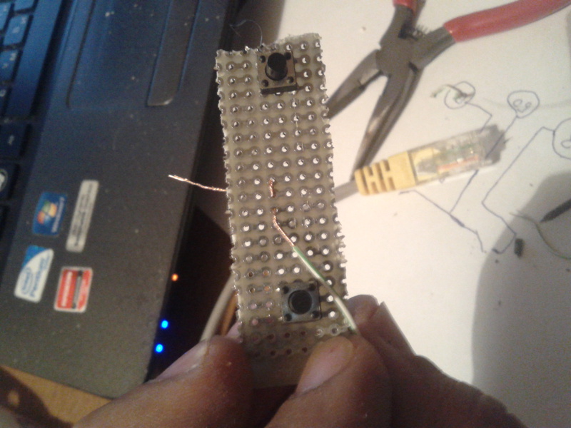
On the tables of the side judges there are referee consoles, which have 2 buttons: red and blue. Information about pressing these buttons is collected by the Arduino controller and transmitted to the program installed on the laptop.
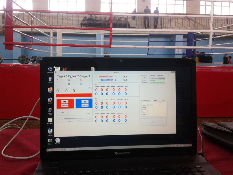
The program analyzes keystrokes and provides information on the outcome of the battle and points scored by the fighter.
The main judge, based on the results of the battle, announces the winner.
Stage 2 wiring diagram

With the scheme, everything is simple, I put each separate button on a separate input of the microcontroller. Resistors used 2.4 kΩ. I didn’t use the shift register because I don’t know how to work with it, and under the current task there are more than enough PINs.
Manufacturing
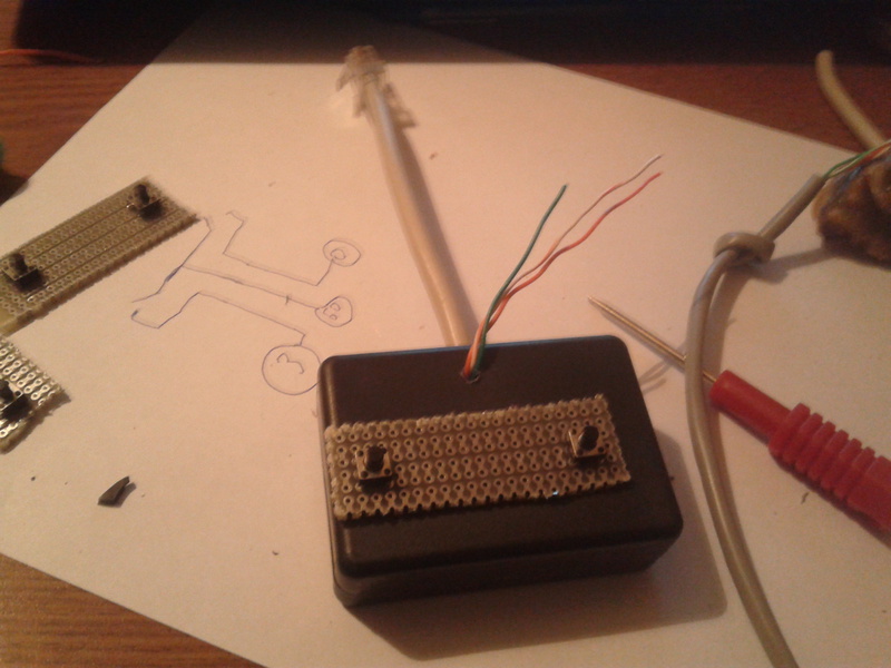
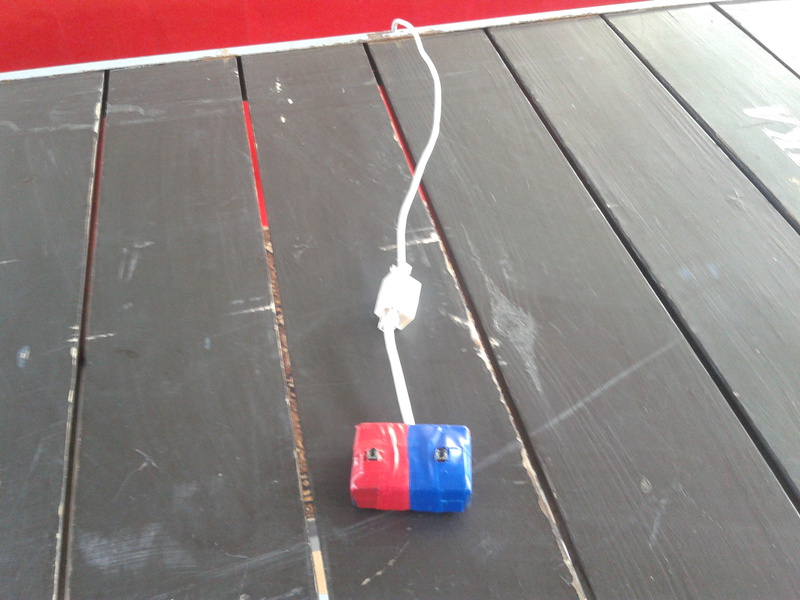
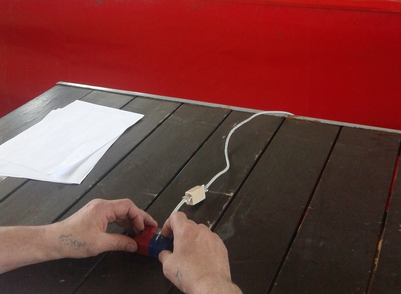
Stage 3 Manufacturing Consoles
The composition of the console:
- Box
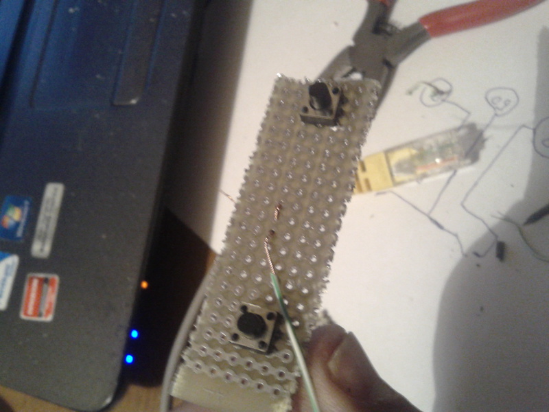
- Piece of circuit board
- Buttons
- Pieces of wire
- Red and blue electrical tape
- Rj45 connector


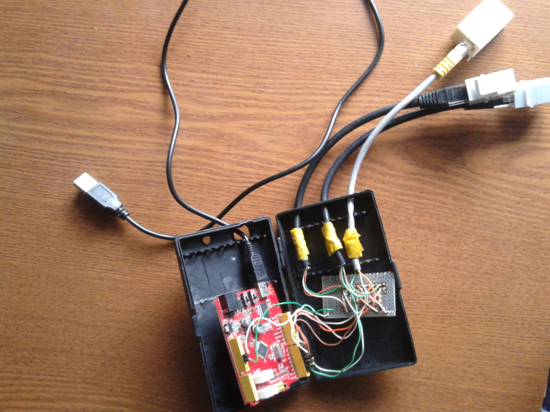
Stage 4 Manufacturing Controller
The composition of the controller:
- Screwdriver case
- Arduino
- circuit board
- Pieces of wire
- Insulating tape
- Pachkordy RJ-45
- USB wire
Programming
Stage 5 program for the controller
In the program for the controller, everything is taken from examples. We are waiting for pressing the buttons, considering the rattle of contacts and the helmet all COM-port:
Controller sketch
#include <Bounce.h> #define BUTTON7 7 #define BUTTON6 6 #define BUTTON5 5 #define BUTTON4 4 #define BUTTON3 3 #define BUTTON2 2 #define LED 13 int state7 = 0; int prevstate7 = 0; int state6 = 0; int prevstate6 = 0; int state5 = 0; int prevstate5 = 0; int state4 = 0; int prevstate4 = 0; int state3 = 0; int prevstate3 = 0; int state2 = 0; int prevstate2 = 0; Bounce bouncer7 = Bounce( BUTTON7,5 ); Bounce bouncer6 = Bounce( BUTTON6,5 ); Bounce bouncer5 = Bounce( BUTTON5,5 ); Bounce bouncer4 = Bounce( BUTTON4,5 ); Bounce bouncer3 = Bounce( BUTTON3,5 ); Bounce bouncer2 = Bounce( BUTTON2,5 ); void setup() { Serial.begin(115200); pinMode(BUTTON7,INPUT); pinMode(BUTTON6,INPUT); pinMode(LED,OUTPUT); } void loop() { // 7 bouncer7.update ( ); int value7 = bouncer7.read(); if ( value7 == HIGH) { digitalWrite(LED, HIGH ); state7 = 1; } else { digitalWrite(LED, LOW ); state7 = 0; } if(state7 != prevstate7){ if(state7 == 1){ Serial.println("7"); } } prevstate7 = state7; // 7 // 6 bouncer6.update ( ); int value6 = bouncer6.read(); if ( value6 == HIGH) { digitalWrite(LED, HIGH ); state6 = 1; } else { digitalWrite(LED, LOW ); state6 = 0; } if(state6 != prevstate6){ if(state6 == 1){ Serial.println("6"); } } prevstate6 = state6; // 6 // 5 bouncer5.update ( ); int value5 = bouncer5.read(); if ( value5 == HIGH) { digitalWrite(LED, HIGH ); state5 = 1; } else { digitalWrite(LED, LOW ); state5 = 0; } if(state5 != prevstate5){ if(state5 == 1){ Serial.println("5"); } } prevstate5 = state5; // 5 // 4 bouncer4.update ( ); int value4 = bouncer4.read(); if ( value4 == HIGH) { digitalWrite(LED, HIGH ); state4 = 1; } else { digitalWrite(LED, LOW ); state4 = 0; } if(state4 != prevstate4){ if(state4 == 1){ Serial.println("4"); } } prevstate4 = state4; // 4 // 3 bouncer3.update ( ); int value3 = bouncer3.read(); if ( value3 == HIGH) { digitalWrite(LED, HIGH ); state3 = 1; } else { digitalWrite(LED, LOW ); state3 = 0; } if(state3 != prevstate3){ if(state3 == 1){ Serial.println("3"); } } prevstate3 = state3; // 3 // 2 bouncer2.update ( ); int value2 = bouncer2.read(); if ( value2 == HIGH) { digitalWrite(LED, HIGH ); state2 = 1; } else { digitalWrite(LED, LOW ); state2 = 0; } if(state2 != prevstate2){ if(state2 == 1){ Serial.println("2"); } } prevstate2 = state2; // 2 } Stage 6 program to control the conduct of battle
First of all, I immediately share the code Download the source code .
All code is written Delphi XE3 as taught him at school. And a small narrative:
- Using the ComPort 4.11 component, we connect to the com port and listen to it.
- depending on the settings of the battle, we listen to the port and output the results in labelX.caption
- at the end of the battle we display the result
The program was written overnight, so beauty is out of the question.
Preparing for the competition
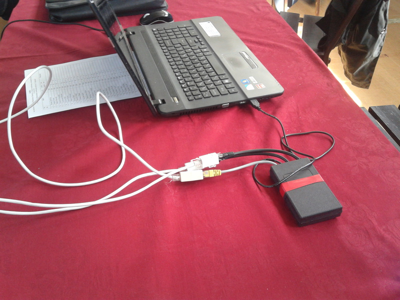
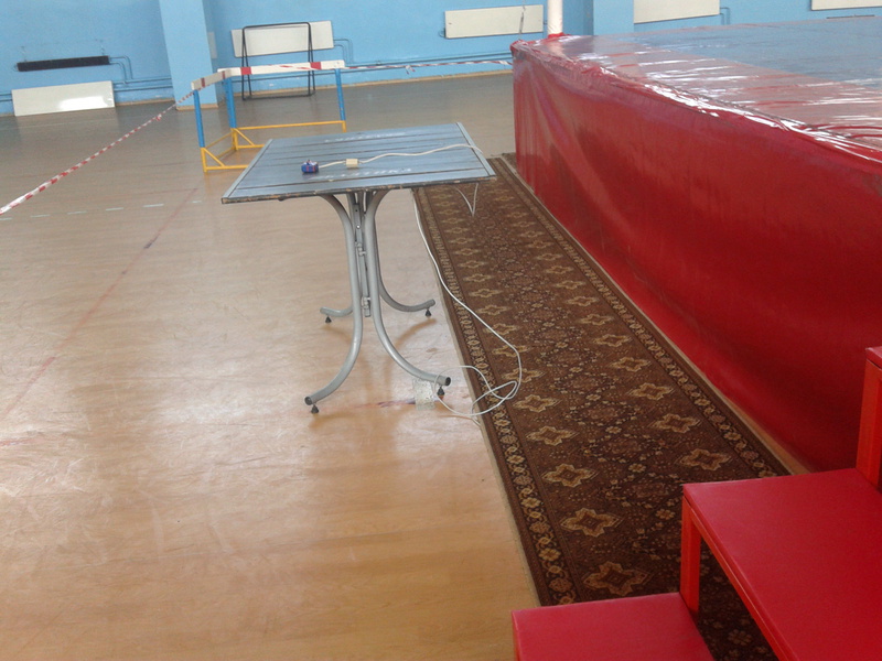
Cabling from the central unit to the side judges
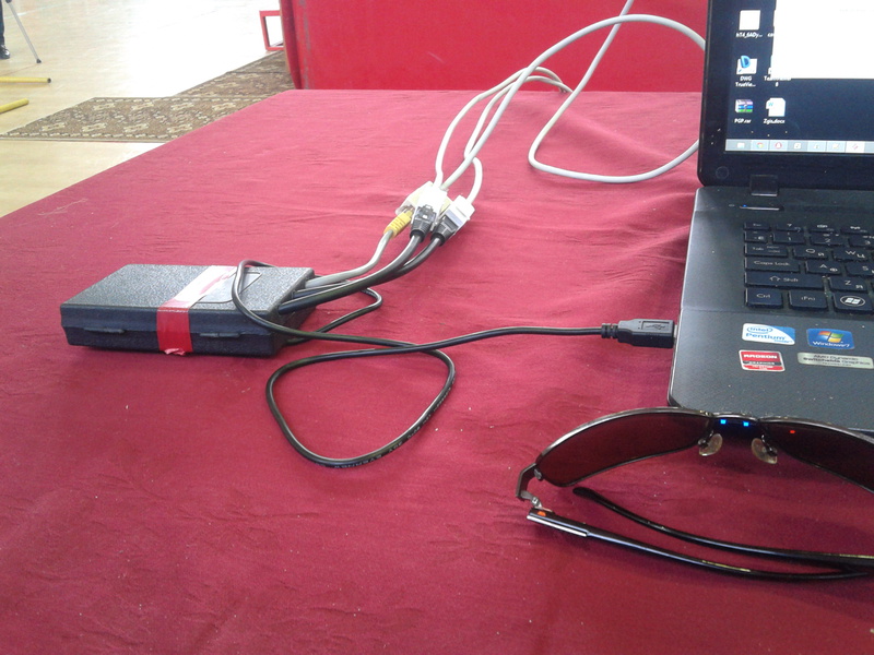


Job judge
How the program works
Results of the competition
According to the results of the two day competitions, a full set of awards was won; more than 150 fights were held.
Thanks to the time saved, the athletes left their cities 4 hours earlier than planned.

findings
- Equipment worked with a bang, without a single failure
- The length of the wires from the central unit to the buttons was 20 meters, while testing the buttons on a 100 meter cable
- The program needs to rework the interface, which is what I do for the preparation of boxing competitions.
- The program requires additions associated with the conclusion on the scoreboard and sound effects
- Using a standard network cable to connect buttons and connectors significantly reduced the cost of the entire structure.
Thanks for attention.
UPD-1: By buttons.
specifically chose these buttons for the following reasons:
1. Feedback is tactile. click when pressed
2. buttons do not have a free wheeling
3. buttons with a free stroke are not pleasant they work before you feel a click
4. users of the system are people with muscles, not lovers of buttons
5. LED feedback is useless because the judge’s gaze is directed to the ring, not to the hands.
UPD-2: the budget of this assembly is unlikely to have exceeded 3,000 rubles
UPD-3 At the request of the source on github
Source: https://habr.com/ru/post/178633/
All Articles