Designing your own computer. Part 1
Introductory part. "Napoleonic plans"
Almost a year ago, I had the idea to understand how a computer works, how it works. And of course, there was a great desire to create your own on elementary logic elements (to be more precise, on transistors).
Then I had only a small idea of his work: I knew that all digital electronics was built on logical elements (for me it was like a postulate), but I couldn’t figure out how the program was being performed, the numbers are summed up, why interrupts ... This list questions can go on and on, but now is not about that.
Define the characteristics of the developed computer:
- Type of Logic: Binary Logic
- Data bus width: 32 bits
- Address bus width: 24 bits (16,777,216 32-bit numbers can be addressed)
- Execution of basic arithmetic, logical, bitwise operations on data, as well as operations on memory cells (mov, xchg)
- The implementation of the memory allocation function (4 assembler instructions are provided)
- Processing data directly and using pointers
Software
For the design of logic circuits, there are many programs. But for large-scale design and debugging, my requirements satisfied only two programs (probably my requirements are too harsh):
Actually requirements:
- Intuitive interface
- Creating large size schemes
- The ability to create modular schemes (scheme in the scheme)
- A variety of basic logic elements with the ability to edit their parameters
- The presence of the element "RAM" and \ or "ROM"
- Ability to load a binary file into RAM \ ROM and save a dump of RAM into a binary file
- Existence of extensive element base for input / output of information and debugging of circuits (buttons, constants, probes, clock generator ...)
In this and all subsequent posts when publishing logic circuits, I will use Logisim due to the fact that I recently switched to Ubuntu, although the entire project is done on Logic Circuit.
Action plan

Since practice without theory does not exist, a theoretical basis is needed to create something. Therefore, today
- A key element of all digital electronics is the transistor;
- Logical elements, their types;
- Technologies for building electronic circuits or building logic elements on transistors;
- The laws of de Morgan or how to reduce the number of valves;
The key element of all digital electronics is the transistor
The base element for the integrated circuit is the transistor.
For the definition of Wikipedia,
A transistor is a radio-electronic component made from a semiconductor material, which allows an input signal to control the current in an electrical circuit.Logic elements consist of transistors. Triggers, adders, logical blocks, and counters are created from logical elements. By combining all this in the right way, you can create your own computer (or ).
')
Logical elements, their types
Logic elements - devices designed to process information in digital form.
A logical function of any complexity can be defined using the following logical elements:
- Element is NOT (inverter). The output will be “1” if and only if the input is “0”;
- Element And (conjunction). The output will be “1” if and only if all inputs have a “1”;
- Element OR (disjunction). The output will be "1", when at least one input will be "1";
- Element of addition modulo 2 (exclusive OR). The output will be “1” if and only if the input has an odd number of “1”;
- Repeater;
- Managing Repeater. Used to connect multiple outputs to one output.
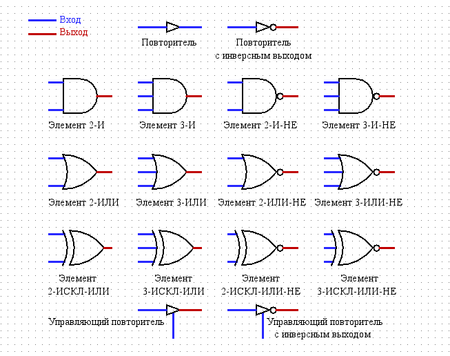
Logic elements in Logisim:
Technologies for building electronic circuits or building logic elements on transistors
The original idea was to build a computer not on the 7400 series chips, but on transistors. And I began to search for the construction of electronic circuits. There are the following:
- Resistor-transistor logic (RTL);
- Diode-transistor logic (DTL);
- Emitter-related logic (ECL);
- Integral-injection logic (IIL, I2L, I3L, I2L);
- CMOS (K-MOS; complementary metal oxide semiconductor).
Then I read for each advantage \ disadvantages, and among them I chose resistor-transistor logic . The choice was obvious due to the fact that this logic has a constructive simplicity and low cost. And also to this logic there is a huge choice of bipolar SMD transistors and SMD resistors. I took the transistors BC847C npn and BC857C pnp.
Having closed my eyes to all the flaws, I plunged for a whole month into recounts of logic elements on transistors. I made several test circuits on a breadboard, using BC547C transistors. I was pleased with the results of the theoretical and practical parts.
Layout:


The last stage is left - designing a synchronous T-flip-flop circuit on 847 transistors, checking its efficiency and analyzing frequency characteristics. The performance test is quite simple - a logical “1” is fed to the “T” input, and a clock from the generator to the “C” input. At the output, I must receive clock pulses, the frequency of which is half the input. If everything works at a reasonable frequency, then the whole computer will work.
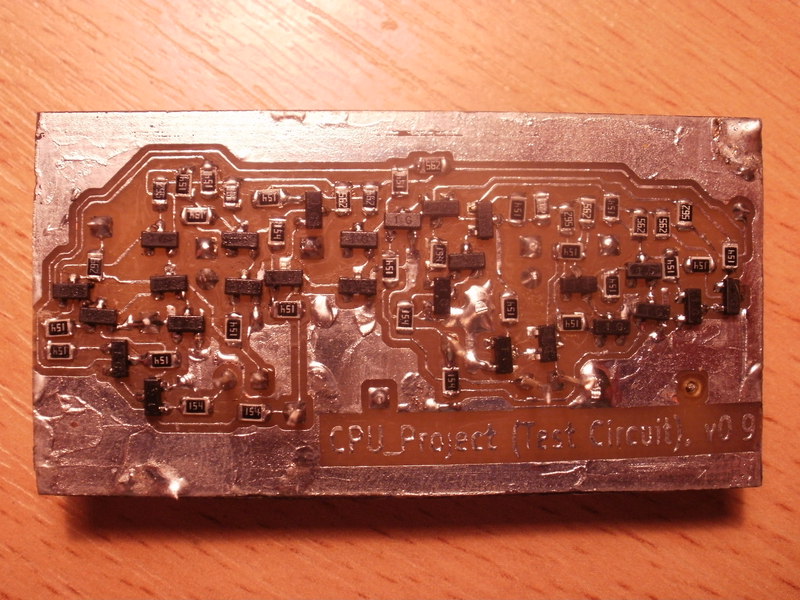
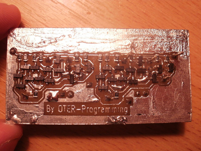
Designed the scheme, which consists of 4 T-flip-flops. Made a printed circuit board photoresistive method, uncomplicated soldered and eventually got just such beauty (the width of the tracks is 0.15mm):
I connected a 5 volt power supply to the circuit, I connected a generator to the input and an oscilloscope to the output. I started testing at 1 MHz, but the circuit did not work. Then he lowered it to 20 kHz - voila, the scheme worked in the right way. By manipulating the supply voltage, I was able to increase the working frequency to 40 kHz ...
Alas, but my expectations did not meet my expectations. In addition, only one T-trigger earned correctly at a frequency of up to 40 kHz, and all the others could not go from a high state to a low state, although the internal RS-triggers worked correctly.
I conducted some more experiments on the construction of logical elements, only already on field-effect transistors. The results were satisfactory, but some problems appeared:
- The high cost of the project (about $ 1000 only for transistors);
- The problem is to get field SMD transistors in Ukraine;
- The problem is to solder 15-20 thousand transistors on a CMOS logic, instead of 7-10 thousand on a RTL.
For myself, I made a good conclusion : it is better to buy 7400 series microchips with logic elements than to make logic elements on transistors. And
Laws de Morgan or how to reduce the number of valves
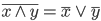
The de Morgan laws are the rules that connect logical operators (disjunction and conjunction) by means of logical negation. In formal logic, they can be written as:
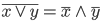
Consider an example of using these rules in action. Suppose we have such a scheme:
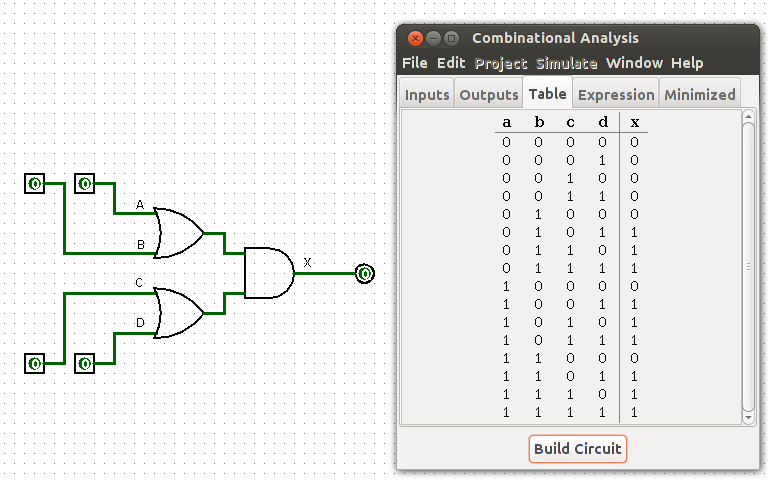
Using the laws of de Morgan scheme can be altered on such:
As you can see from the truth tables, the logic of these schemes is identical.
Now a small postulate : for logic elements (except logical NOT) on CMOS logic with inverse output (for example, logical 2-NOT) it is necessary for two transistors less than for logical elements with non-inverse output (for example, logical 2).
Then, for the first circuit will need 18 transistors, and for the second - 12 transistors. Moreover, the second circuit will work faster due to the fact that fewer gates are used and the signal will go an order of magnitude faster.
Future plans
In the next post I will talk about triggers and we will begin to design the ALU.
Source: https://habr.com/ru/post/178071/
All Articles