LinkMeUp. Release 2
Hello colleagues.
In the new issue we discuss
1) SDH / PDH (Synchronous Digital Hierarchy / Plesiochronous Digital Hierarchy)
2) Spectral channel multiplexing systems in optical networks
3) Redundant Ethernet technology. Alternatives to STP - ERPS, RRPP.
')
Download podcast .
The topics that we found interesting were not included in the podcast, we brought to Overtime .
I am sure that every telecommunications engineer knows or at least heard such a name as an E1 stream. And the most advanced have even heard about the Kotelnikov theorem, the sampling rate and the PCM. The history of the development of PDH networks (Plesiochronous Digital Hierarchy) began with the fact that by the mid-70s it became clear that further frequency multiplexing is impossible in one physical communication channel, it is limited by cable PP, increase in attenuation, complexity of filters and amplifiers, therefore the transition began to tsss.
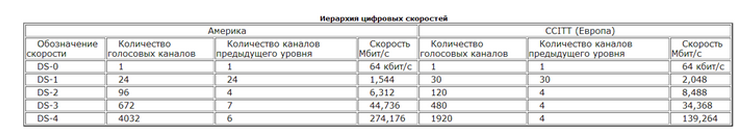
In the early 1980s, 3 such systems were developed (in Europe, North America and Japan). Despite the same principles, the systems used different multiplexing factors at different levels of hierarchies. A description of the interfaces of these interfaces and the levels of multiplexing is given in recommendation G.703.
The essence of the technology is quite simple - the E1 stream consists of 32 BCCs, each of which has a speed of 64 kbit / s, 2 of them are service ones, in which signaling and synchronization are transmitted. The combination takes place at the expense of the PDH multiplexer (typical NATEKS multiplexer, Raisecom, and others). Without going into details, it looks like this - the incoming bits in the streams are compressed by a number of times, a multiple of the output stream level and inserted into certain positions, then the service information of the higher stream is added.
When multiplexing multiple user streams in PDH multiplexers, a technique called bit stuffing is used. This technique is resorted to when the speed of the user stream is somewhat lower than the speed of the combined stream - such problems can occur in a network consisting of a large number of multiplexers, despite all efforts to centrally synchronize network nodes (there is nothing perfect in nature, including perfectly synchronous network nodes). As a result, the PDH multiplexer periodically encounters a situation where it “lacks” a bit to represent a user stream in the combined stream. In this case, the multiplexer simply inserts the insert bits into the combined stream and marks this fact in the service bits of the combined frame. When demultiplexing the combined stream, the insert bit is removed from the user stream, which is returned to its original state. The technique of bit-stuffing is used in both international and American versions of PDH.
The physical layer of PDH technology supports various types of cables: twisted pair, coaxial cable, fiber optic cable. The main option of subscriber access to channels T-1 / E-1 is a cable of two twisted pairs with RJ-48 connectors.
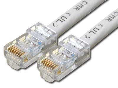
Two pairs are required for duplex data transfer with a speed of 1.544 / 2.048 Mbit / s. To represent the signals used:
in channels T-1 - potential bipolar code B8ZS;
in channels E-1 - bipolar potential code HDB3.
This technology has several significant drawbacks:
One of the main drawbacks is the complexity of multiplexing and demultiplexing user data. The term “plesiochronous” used for this technology speaks of the reason for this phenomenon — the lack of complete synchronization of data streams when combining low-speed channels into higher-speed ones. Initially, an asynchronous approach to frame transmission spawned the insertion of a bit or several synchronization bits between frames. As a result, to extract user data from the combined channel, it is necessary to completely demultiplex the frames of this combined channel. For example, if it is necessary to receive data of one 64 kbit / s subscriber channel from the frames of the TZ channel, it is necessary to demultiplex these frames to the level of T2 frames, then to the level of T1 frames, and then demultiplex the T1 frames themselves.
Another significant disadvantage of PDH technology is the lack of developed built-in procedures for monitoring and managing the network. Service bits provide little information about the channel status, do not allow to configure it, etc.
The third drawback is the PDH hierarchy, which is too low for modern concepts. Fiber optic cables allow data transmission at speeds of several gigabits per second over a single fiber, which allows tens of thousands of user channels to be consolidated in one cable, but PDH does not implement this feature — its speed hierarchy ends at 139 Mbps.
Therefore, the next stage of development was the SDH networks - fully synchronous networks.
The SDH (Synchronous Digital Hierarchy) system provides standard levels of information structures, that is, a set of standard speeds. The basic speed level is STM-1 155.52 Mbit / s. Digital speeds of higher levels are determined by multiplying the flow rate of STM-1, respectively, by 4, 16, 64, and so on: 622 Mbit / s (STM-4), 2.5 Gbit / s (STM-16), 10 Gbit / s (STM-64) and 40 Gbit / s (STM-256).
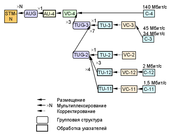
All information in the SDH system is transmitted in containers. The container is a structured data transmitted in the system. If the PDH system generates the traffic that needs to be transmitted over the SDH system, the PDH data is first structured into containers, and then a header and pointers are added to the container, resulting in a synchronous STM-1 transport module. Through the network, STM-1 containers are transmitted in the SDH system of different levels (STM-n), but in all cases the generated STM-1 can only be added to another transport module, i.e. there is a multiplexing of transport modules.
Another important concept directly related to the general understanding of SDH technology is the concept of a virtual container VC. As a result of adding a path (route) header to the container, a virtual container is obtained. Virtual containers are ideologically and technologically connected to containers, so that container C-12 corresponds to virtual container VC-12 (E1 stream transfer), C-3 - VC-3 (E3 stream transfer), C-4 - VC-4 container (STM-1 stream transmission).
Since the low-speed PDH signals are multiplexed into the frame structure of the high-speed SDH signals using the byte-multiplexing method, their arrangement in the high-speed signal frame is fixed and determined or, say, predictable. Therefore, a low-speed SDH signal, for example, 155 Mbps (STM-1) can be directly added or separated from a high-speed signal, for example, 2.5 Gbit / s (STM-16). This simplifies the process of multiplexing and demultiplexing the signal and makes the SDH hierarchy particularly suitable for high-speed, high-performance fiber-optic transmission systems.
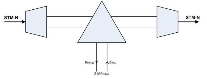
Since the method of synchronous multiplexing and flexible mapping of the structure is adopted, low-speed PDH signals (for example, 2 Mbit / s) can also be multiplexed into an SDH (STM-N) signal. Their location in the STM-N frame is also predictable. Therefore, a low-speed tributary signal (up to the DS-0 signal, that is, one PDH time slot, 64 kbps) can be directly added or extracted from the STM-N signal. Note that this is not the same with the above process of adding / extracting a low-speed SDH signal to / from a high-speed SDH signal. Here it refers to the direct addition / allocation of a low-speed tributary signal such as 2 Mbps, 34 Mbps and 140 Mbps to / from the SDH signal. This eliminates the need to use a large amount of equipment multiplexing / demultiplexing (interconnected), increases reliability and reduces the likelihood of signal quality degradation, reduces cost, power consumption and equipment complexity. Adding / highlighting services is further simplified.
Spectral channel multiplexing (Wavelength-division multiplexing, WDM, literally wavelength division multiplexing) is a technology that allows you to simultaneously transmit several information channels over a single optical fiber at different carrier frequencies.
WDM technology can significantly increase the channel capacity (by 2003, the speed reached 10.72 Tbit / s, and by 2012 - 20 Tbit / s), and it allows the use of already laid fiber-optic lines. Thanks to WDM, it is possible to organize two-way multi-channel traffic transmission over a single fiber. The advantage of DWDM systems is the ability to transmit a high-speed signal over ultra-long distances without using intermediate points (without signal regeneration and intermediate amplifiers)
In the simplest case, each laser transmitter generates a signal at a certain frequency from the frequency plan. All of these signals before being introduced into the optical fiber are combined with a multiplexer (MUX). At the receiving end, signals are similarly divided by a demultiplexer (DEMUX). Here, as well as in SDH networks, the multiplexer is a key element. The signals come at the wavelengths of the client equipment, and the transmission occurs at the lengths corresponding to the ITU DWDM frequency plan.
Historically, the first emerged two-wavelength WDM systems operating at central wavelengths from the second and third transparency windows of quartz fiber (1310 and 1550 nm). The main advantage of such systems is that due to the large spectral separation the influence of the channels on each other is completely absent. This method allows you to either double the speed of transmission over a single optical fiber, or to organize duplex communication.
Modern WDM systems based on the standard frequency plan (ITU-T Rec. G.692) can be divided into three groups:
Coarse WDM (Coarse WDM - CWDM) are systems with a frequency separation of 200 GHz channels, allowing multiplexing of up to 18 channels.
(Currently used CWDMs operate in the band from 1270nm to 1610nm, the gap between the channels is 20nm (200Ghz), 16 spectral channels can be multiplexed)
dense WDM (Dense WDM - DWDM) - systems with a channel spacing of at least 100 GHz, allowing multiplexing of no more than 40 channels.
High-density WDM (High Dense WDM - HDWDM) systems with a channel spacing of 50 GHz and less, allowing multiplexing of at least 64 channels.
The frequency plan for CWDM systems is defined by the ITU G.694.2 standard. The field of application of CWDM technology is urban networks with a distance of up to 50 km. The advantage of this type of WDM systems is low (compared to other types) equipment cost due to lower component requirements.
The frequency plan for DWDM systems is defined by the ITU G.694.1 standard. A scope - the main networks. This type of WDM systems places higher demands on components than CWDM (the width of the spectrum of the radiation source, the temperature stabilization of the source, etc.). The impetus to the rapid development of DWDM networks has given rise to inexpensive and efficient fiber erbium amplifiers (EDFA) operating in the interval from 1525 to 1565 nm (the third transparency window of quartz fiber).
We have already found out that SDH was originally designed for use in ring topologies and already in itself carries protection against loops - APS. But on Ethernet, this problem and the issue of the broadcasting storm are standing tall.
The fight began in 1985 with the invention of STP. Then RSTP, in the early 2000s saw the light of the MSTP. They all have the same problems.
First, the time of convergence, even for modifications - it can be a few seconds. For voice and video streaming this is already quite noticeable.
Secondly, security. STP has no authentication and is subject to attacks. And besides, one Topology Change package can put an entire network.
Thirdly, the path between two adjacent switches may lie through the root switch, that is, it will be suboptimal.
Then it is almost not suitable for large networks.
STP comes to replace the new standard 802.1aq. Humanly, this is SPB - Shortest Path Bridging.
It converges faster, allows you to recycle all links, in contrast to STP. Works in conjunction with the Multi Mac Registration Protocol (MMRP) and ISIS protocols. In 2012, this standard was officially approved by IEEE.
It is fully compatible with the STP family.
Another alternative is TRILL - Transparent Interconnection of Lots of Links. Uses the concept of routing bridges. Something like Link-State routing protocol, but only for switching.
Although, this is for Layer 2 networks of a very large scale, for data centers.
The next thing that comes to mind is MLAG or MC-LAG Multi-Chassis Link Aggregation Group. That is, it is a modification of the usual port aggregation, when your links start on one device and end on different ones. That is, not only link redundancy, as in a regular LAG, but also device redundancy. The problem with him is that there are no universal standards, and there is something for everyone. Cross two vendors - will not work.
But I propose to discuss all these really interesting topics in the next issues. And today let's focus on another topic - Ethernet ring topologies.
SDH was originally designed to work in a ring and backup. Well, how not to want to realize this in a normal Ethernet? And it appeared and did - ERPS - Ethernet Ring Protection Switching.
It works only on the rings. No full-mesh or part-mesh is supported.
As far as I know, its implementation exists in both tsiska and Juniper and other vendors. But, since I work at Huawei, I can tell you in detail about our proprietary RRPP protocol, which is the same. It stands for Rapid Ring Protection Protocol.
Its two main advantages are that the convergence time is less than 50 ms. Almost 2 orders of magnitude smaller than STP, and then it supports large L2 networks. That is, if an STP in the ring can have something around 14 devices, then RRPP and with it ERPS are not limited to this.
Principle of operation.
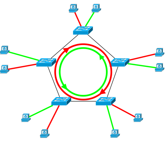
Take the example of a network of city scales. In it, 25 aggregation switches are scattered around the inner perimeter. A star would be ideal in terms of stability, but it’s not very rational, more logical is a ring. Thus, we get protection from the fall of the link and the failure of a single device.
From these 25 switches one main is chosen - the master. This switch becomes responsible for the integrity of the ring and the absence of a loop.
Each switch has two ports, one east, the other western, respectively, ports of different switches must look at each other east to west.
The Master also has one of them as the one he chooses active, and the second one blocks. It turns out just such a chain of 25 switches. And the frame from the 25th, to get to the top, will have to go through 24, 23, 22, etc., that is, through the whole chain.
The wizard sends hello messages regularly. If the blocked port did not receive such a packet within the Fail_timer or received information about the link drop, RRPP unblocks it.
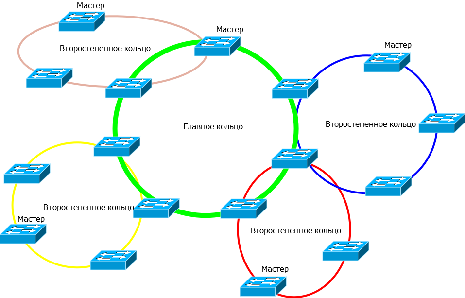
One such large ring may have petals - subordinate rings. That is, if, for example, two switches serve a certain area, then the lobe starts at one of them and ends at the other. Inside it are the same laws of reservation. So it turns out such a daisy.
And at the same time, I did not come across real applications of ERPS. At the same time, RRPP is fully used in the networks of operators in those areas where all the equipment is Huawei.
In the new issue we discuss
1) SDH / PDH (Synchronous Digital Hierarchy / Plesiochronous Digital Hierarchy)
2) Spectral channel multiplexing systems in optical networks
3) Redundant Ethernet technology. Alternatives to STP - ERPS, RRPP.
')
Download podcast .
The topics that we found interesting were not included in the podcast, we brought to Overtime .
SDH / PDH
I am sure that every telecommunications engineer knows or at least heard such a name as an E1 stream. And the most advanced have even heard about the Kotelnikov theorem, the sampling rate and the PCM. The history of the development of PDH networks (Plesiochronous Digital Hierarchy) began with the fact that by the mid-70s it became clear that further frequency multiplexing is impossible in one physical communication channel, it is limited by cable PP, increase in attenuation, complexity of filters and amplifiers, therefore the transition began to tsss.
In the early 1980s, 3 such systems were developed (in Europe, North America and Japan). Despite the same principles, the systems used different multiplexing factors at different levels of hierarchies. A description of the interfaces of these interfaces and the levels of multiplexing is given in recommendation G.703.
The essence of the technology is quite simple - the E1 stream consists of 32 BCCs, each of which has a speed of 64 kbit / s, 2 of them are service ones, in which signaling and synchronization are transmitted. The combination takes place at the expense of the PDH multiplexer (typical NATEKS multiplexer, Raisecom, and others). Without going into details, it looks like this - the incoming bits in the streams are compressed by a number of times, a multiple of the output stream level and inserted into certain positions, then the service information of the higher stream is added.
When multiplexing multiple user streams in PDH multiplexers, a technique called bit stuffing is used. This technique is resorted to when the speed of the user stream is somewhat lower than the speed of the combined stream - such problems can occur in a network consisting of a large number of multiplexers, despite all efforts to centrally synchronize network nodes (there is nothing perfect in nature, including perfectly synchronous network nodes). As a result, the PDH multiplexer periodically encounters a situation where it “lacks” a bit to represent a user stream in the combined stream. In this case, the multiplexer simply inserts the insert bits into the combined stream and marks this fact in the service bits of the combined frame. When demultiplexing the combined stream, the insert bit is removed from the user stream, which is returned to its original state. The technique of bit-stuffing is used in both international and American versions of PDH.
The physical layer of PDH technology supports various types of cables: twisted pair, coaxial cable, fiber optic cable. The main option of subscriber access to channels T-1 / E-1 is a cable of two twisted pairs with RJ-48 connectors.
Two pairs are required for duplex data transfer with a speed of 1.544 / 2.048 Mbit / s. To represent the signals used:
in channels T-1 - potential bipolar code B8ZS;
in channels E-1 - bipolar potential code HDB3.
This technology has several significant drawbacks:
One of the main drawbacks is the complexity of multiplexing and demultiplexing user data. The term “plesiochronous” used for this technology speaks of the reason for this phenomenon — the lack of complete synchronization of data streams when combining low-speed channels into higher-speed ones. Initially, an asynchronous approach to frame transmission spawned the insertion of a bit or several synchronization bits between frames. As a result, to extract user data from the combined channel, it is necessary to completely demultiplex the frames of this combined channel. For example, if it is necessary to receive data of one 64 kbit / s subscriber channel from the frames of the TZ channel, it is necessary to demultiplex these frames to the level of T2 frames, then to the level of T1 frames, and then demultiplex the T1 frames themselves.
Another significant disadvantage of PDH technology is the lack of developed built-in procedures for monitoring and managing the network. Service bits provide little information about the channel status, do not allow to configure it, etc.
The third drawback is the PDH hierarchy, which is too low for modern concepts. Fiber optic cables allow data transmission at speeds of several gigabits per second over a single fiber, which allows tens of thousands of user channels to be consolidated in one cable, but PDH does not implement this feature — its speed hierarchy ends at 139 Mbps.
Therefore, the next stage of development was the SDH networks - fully synchronous networks.
The SDH (Synchronous Digital Hierarchy) system provides standard levels of information structures, that is, a set of standard speeds. The basic speed level is STM-1 155.52 Mbit / s. Digital speeds of higher levels are determined by multiplying the flow rate of STM-1, respectively, by 4, 16, 64, and so on: 622 Mbit / s (STM-4), 2.5 Gbit / s (STM-16), 10 Gbit / s (STM-64) and 40 Gbit / s (STM-256).
All information in the SDH system is transmitted in containers. The container is a structured data transmitted in the system. If the PDH system generates the traffic that needs to be transmitted over the SDH system, the PDH data is first structured into containers, and then a header and pointers are added to the container, resulting in a synchronous STM-1 transport module. Through the network, STM-1 containers are transmitted in the SDH system of different levels (STM-n), but in all cases the generated STM-1 can only be added to another transport module, i.e. there is a multiplexing of transport modules.
Another important concept directly related to the general understanding of SDH technology is the concept of a virtual container VC. As a result of adding a path (route) header to the container, a virtual container is obtained. Virtual containers are ideologically and technologically connected to containers, so that container C-12 corresponds to virtual container VC-12 (E1 stream transfer), C-3 - VC-3 (E3 stream transfer), C-4 - VC-4 container (STM-1 stream transmission).
Since the low-speed PDH signals are multiplexed into the frame structure of the high-speed SDH signals using the byte-multiplexing method, their arrangement in the high-speed signal frame is fixed and determined or, say, predictable. Therefore, a low-speed SDH signal, for example, 155 Mbps (STM-1) can be directly added or separated from a high-speed signal, for example, 2.5 Gbit / s (STM-16). This simplifies the process of multiplexing and demultiplexing the signal and makes the SDH hierarchy particularly suitable for high-speed, high-performance fiber-optic transmission systems.
Since the method of synchronous multiplexing and flexible mapping of the structure is adopted, low-speed PDH signals (for example, 2 Mbit / s) can also be multiplexed into an SDH (STM-N) signal. Their location in the STM-N frame is also predictable. Therefore, a low-speed tributary signal (up to the DS-0 signal, that is, one PDH time slot, 64 kbps) can be directly added or extracted from the STM-N signal. Note that this is not the same with the above process of adding / extracting a low-speed SDH signal to / from a high-speed SDH signal. Here it refers to the direct addition / allocation of a low-speed tributary signal such as 2 Mbps, 34 Mbps and 140 Mbps to / from the SDH signal. This eliminates the need to use a large amount of equipment multiplexing / demultiplexing (interconnected), increases reliability and reduces the likelihood of signal quality degradation, reduces cost, power consumption and equipment complexity. Adding / highlighting services is further simplified.
Optical networks and spectral channel multiplexing systems
Spectral channel multiplexing (Wavelength-division multiplexing, WDM, literally wavelength division multiplexing) is a technology that allows you to simultaneously transmit several information channels over a single optical fiber at different carrier frequencies.
WDM technology can significantly increase the channel capacity (by 2003, the speed reached 10.72 Tbit / s, and by 2012 - 20 Tbit / s), and it allows the use of already laid fiber-optic lines. Thanks to WDM, it is possible to organize two-way multi-channel traffic transmission over a single fiber. The advantage of DWDM systems is the ability to transmit a high-speed signal over ultra-long distances without using intermediate points (without signal regeneration and intermediate amplifiers)
In the simplest case, each laser transmitter generates a signal at a certain frequency from the frequency plan. All of these signals before being introduced into the optical fiber are combined with a multiplexer (MUX). At the receiving end, signals are similarly divided by a demultiplexer (DEMUX). Here, as well as in SDH networks, the multiplexer is a key element. The signals come at the wavelengths of the client equipment, and the transmission occurs at the lengths corresponding to the ITU DWDM frequency plan.
Historically, the first emerged two-wavelength WDM systems operating at central wavelengths from the second and third transparency windows of quartz fiber (1310 and 1550 nm). The main advantage of such systems is that due to the large spectral separation the influence of the channels on each other is completely absent. This method allows you to either double the speed of transmission over a single optical fiber, or to organize duplex communication.
Modern WDM systems based on the standard frequency plan (ITU-T Rec. G.692) can be divided into three groups:
Coarse WDM (Coarse WDM - CWDM) are systems with a frequency separation of 200 GHz channels, allowing multiplexing of up to 18 channels.
(Currently used CWDMs operate in the band from 1270nm to 1610nm, the gap between the channels is 20nm (200Ghz), 16 spectral channels can be multiplexed)
dense WDM (Dense WDM - DWDM) - systems with a channel spacing of at least 100 GHz, allowing multiplexing of no more than 40 channels.
High-density WDM (High Dense WDM - HDWDM) systems with a channel spacing of 50 GHz and less, allowing multiplexing of at least 64 channels.
The frequency plan for CWDM systems is defined by the ITU G.694.2 standard. The field of application of CWDM technology is urban networks with a distance of up to 50 km. The advantage of this type of WDM systems is low (compared to other types) equipment cost due to lower component requirements.
The frequency plan for DWDM systems is defined by the ITU G.694.1 standard. A scope - the main networks. This type of WDM systems places higher demands on components than CWDM (the width of the spectrum of the radiation source, the temperature stabilization of the source, etc.). The impetus to the rapid development of DWDM networks has given rise to inexpensive and efficient fiber erbium amplifiers (EDFA) operating in the interval from 1525 to 1565 nm (the third transparency window of quartz fiber).
Ethernet Reservation Technologies
We have already found out that SDH was originally designed for use in ring topologies and already in itself carries protection against loops - APS. But on Ethernet, this problem and the issue of the broadcasting storm are standing tall.
The fight began in 1985 with the invention of STP. Then RSTP, in the early 2000s saw the light of the MSTP. They all have the same problems.
First, the time of convergence, even for modifications - it can be a few seconds. For voice and video streaming this is already quite noticeable.
Secondly, security. STP has no authentication and is subject to attacks. And besides, one Topology Change package can put an entire network.
Thirdly, the path between two adjacent switches may lie through the root switch, that is, it will be suboptimal.
Then it is almost not suitable for large networks.
STP comes to replace the new standard 802.1aq. Humanly, this is SPB - Shortest Path Bridging.
It converges faster, allows you to recycle all links, in contrast to STP. Works in conjunction with the Multi Mac Registration Protocol (MMRP) and ISIS protocols. In 2012, this standard was officially approved by IEEE.
It is fully compatible with the STP family.
Another alternative is TRILL - Transparent Interconnection of Lots of Links. Uses the concept of routing bridges. Something like Link-State routing protocol, but only for switching.
Although, this is for Layer 2 networks of a very large scale, for data centers.
The next thing that comes to mind is MLAG or MC-LAG Multi-Chassis Link Aggregation Group. That is, it is a modification of the usual port aggregation, when your links start on one device and end on different ones. That is, not only link redundancy, as in a regular LAG, but also device redundancy. The problem with him is that there are no universal standards, and there is something for everyone. Cross two vendors - will not work.
But I propose to discuss all these really interesting topics in the next issues. And today let's focus on another topic - Ethernet ring topologies.
SDH was originally designed to work in a ring and backup. Well, how not to want to realize this in a normal Ethernet? And it appeared and did - ERPS - Ethernet Ring Protection Switching.
It works only on the rings. No full-mesh or part-mesh is supported.
As far as I know, its implementation exists in both tsiska and Juniper and other vendors. But, since I work at Huawei, I can tell you in detail about our proprietary RRPP protocol, which is the same. It stands for Rapid Ring Protection Protocol.
Its two main advantages are that the convergence time is less than 50 ms. Almost 2 orders of magnitude smaller than STP, and then it supports large L2 networks. That is, if an STP in the ring can have something around 14 devices, then RRPP and with it ERPS are not limited to this.
Principle of operation.
Take the example of a network of city scales. In it, 25 aggregation switches are scattered around the inner perimeter. A star would be ideal in terms of stability, but it’s not very rational, more logical is a ring. Thus, we get protection from the fall of the link and the failure of a single device.
From these 25 switches one main is chosen - the master. This switch becomes responsible for the integrity of the ring and the absence of a loop.
Each switch has two ports, one east, the other western, respectively, ports of different switches must look at each other east to west.
The Master also has one of them as the one he chooses active, and the second one blocks. It turns out just such a chain of 25 switches. And the frame from the 25th, to get to the top, will have to go through 24, 23, 22, etc., that is, through the whole chain.
The wizard sends hello messages regularly. If the blocked port did not receive such a packet within the Fail_timer or received information about the link drop, RRPP unblocks it.
One such large ring may have petals - subordinate rings. That is, if, for example, two switches serve a certain area, then the lobe starts at one of them and ends at the other. Inside it are the same laws of reservation. So it turns out such a daisy.
And at the same time, I did not come across real applications of ERPS. At the same time, RRPP is fully used in the networks of operators in those areas where all the equipment is Huawei.
Source: https://habr.com/ru/post/177899/
All Articles