Border Gateway Protocol. Laboratory work
Hi, Habr! My first article and in it I want to present a little lab work on configuring BGP (Border Gateway Protocol) on Cisco routers. Many of you have heard what BGP is, but not everyone happened to try this protocol in practice. This laboratory work will be interesting for them.
The article will have little theory, so for those who hear about BGP for the first time, I send first to visit this , this or, in fact, this .
For laboratory work, I recommend using the excellent GNS3 simulator, which is easy to find online.
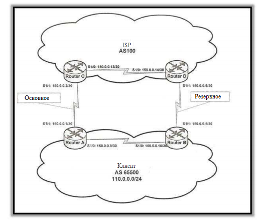
The goal of the lab is to configure the client and operator routers so that they can be addressed multiple times using single ISP connections. Actually the scheme of our future network:
')
And so, we want the connection between routers A and C to be the primary for incoming and outgoing traffic, and the connection between B and D to be redundant and used only in the event of a primary crash.
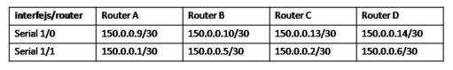
Interfaces must be configured according to the table:
For Serial 1/1 Router A:
The remaining interfaces should be configured independently in a similar way.
Each router must have an ASN number (in accordance with the scheme), which determines to which AS the router belongs. Plus, each router will serve two sessions: one iBGP with a router in the same AS for operation within an autonomous system and one eBGP with a router located in the other AS for operation between autonomous systems. Sessions must be configured on both sides of the connection.
The configuration of the remaining routers remains an independent task.
The next thing we will do is use the non-standard mechanism offered by Cisco, next-hop-self. Its essence is that it allows Next_Hop to change the address before announcing it to another router located in the same AS. The router changes the value of the Next_Hop attribute to its own address. Due to this, we should not configure intra-domain routing in each AS. This mechanism should only be configured between routers in the same AS.
Again, the configuration of the remaining routers is independent.
The address space used in AS 65500 is 110.0.0.0/24. To simulate such a network connected to a router, you can configure a Loopback interface on Router B.
Routers must then announce the subnets to which they have access. Router B announces a 110.0.0.0 network with a mask of 255.255.255.0, which it has on the Loopback 0 interface.
Routers C and D will announce A and B only the default route (the route that will be used for all outgoing traffic from AS 65500).
If we want routers A and B to use only the primary connection for outgoing traffic, you can use the Local Preference attribute. By default, the attribute has a value of 100. Local Preference is exchanged between all routers located in the same AS. The higher the attribute value, the higher the connection priority. You can change the Local Preference value using the Route map.
Make the connection between A and C main:
Then:
For the Local Preference changes to take effect, you must reset the previous BGP session settings.
To check the correctness of the configuration, and at the same time enjoy the result, you can use traceroute, turning off and on certain interfaces, thereby simulating a connection failure.
We want C and D routers to direct all their traffic through the primary link. For this we can use the attribute MED. The primary connection should receive a lower value (in our case MED 20) than the reserve (MED 30). We do this with the help of the same Route map.
On router B, we do the same with the value of MED 50. And do not forget to reset the settings on the ISP routers so that we can get new metrics values.
It's all.
Thanks for attention!
I apologize for spelling errors. At school, the language was not a strong point, and learning over the hill, Russian is slowly forgotten.
The article will have little theory, so for those who hear about BGP for the first time, I send first to visit this , this or, in fact, this .
For laboratory work, I recommend using the excellent GNS3 simulator, which is easy to find online.
purpose
The goal of the lab is to configure the client and operator routers so that they can be addressed multiple times using single ISP connections. Actually the scheme of our future network:
')
Configuration
And so, we want the connection between routers A and C to be the primary for incoming and outgoing traffic, and the connection between B and D to be redundant and used only in the event of a primary crash.
Interface Configuration
Interfaces must be configured according to the table:
For Serial 1/1 Router A:
R1(config)# interface S1/1 R1(config-if)# ip address 150.0.0.1 255.255.255.252 R1(config-if)# no shutdown The remaining interfaces should be configured independently in a similar way.
BGP configuration
Each router must have an ASN number (in accordance with the scheme), which determines to which AS the router belongs. Plus, each router will serve two sessions: one iBGP with a router in the same AS for operation within an autonomous system and one eBGP with a router located in the other AS for operation between autonomous systems. Sessions must be configured on both sides of the connection.
R1(config)# router bgp 65500 R1(config-router)# neighbor 150.0.0.10 remote-as 65500 R1(config-router)# neighbor 150.0.0.2 remote-as 100 The configuration of the remaining routers remains an independent task.
The next thing we will do is use the non-standard mechanism offered by Cisco, next-hop-self. Its essence is that it allows Next_Hop to change the address before announcing it to another router located in the same AS. The router changes the value of the Next_Hop attribute to its own address. Due to this, we should not configure intra-domain routing in each AS. This mechanism should only be configured between routers in the same AS.
R1(config)# router bgp 65500 R1(config-router)# neighbor 150.0.0.10 next-hop-self Again, the configuration of the remaining routers is independent.
The address space used in AS 65500 is 110.0.0.0/24. To simulate such a network connected to a router, you can configure a Loopback interface on Router B.
R2(config)# interface loopback 0 R2(config-if)# ip address 110.0.0.1 255.255.255.0 Routers must then announce the subnets to which they have access. Router B announces a 110.0.0.0 network with a mask of 255.255.255.0, which it has on the Loopback 0 interface.
R2(config)# router bgp 65500 R2(config-router)# network 110.0.0.0 mask 255.255.255.0 Routers C and D will announce A and B only the default route (the route that will be used for all outgoing traffic from AS 65500).
R3(config)# router bgp 100 R3(config-router)# neighbor 150.0.0.1 default-originate Outbound traffic management
If we want routers A and B to use only the primary connection for outgoing traffic, you can use the Local Preference attribute. By default, the attribute has a value of 100. Local Preference is exchanged between all routers located in the same AS. The higher the attribute value, the higher the connection priority. You can change the Local Preference value using the Route map.
Make the connection between A and C main:
R1(config)# router-map primary R1(config-route-map)# match ip address 1 R1(config-route-map)# set local-preference 150 R1(config-route-map)# exit R1(config)# access-list 1 permit host 0.0.0.0 Then:
R1(config)# router bgp 65500 R1(config-router)# neighbor 150.0.0.2 route-map primary in For the Local Preference changes to take effect, you must reset the previous BGP session settings.
R1# clear ip bgp * To check the correctness of the configuration, and at the same time enjoy the result, you can use traceroute, turning off and on certain interfaces, thereby simulating a connection failure.
Incoming traffic management
We want C and D routers to direct all their traffic through the primary link. For this we can use the attribute MED. The primary connection should receive a lower value (in our case MED 20) than the reserve (MED 30). We do this with the help of the same Route map.
R1(config)# route-map trafic_out permit 10 R1(config-route-map)# match ip address 10 R1(config-route-map)# set metric 20 R1(config-route-map)# exit R1(config)# access-list 10 permit host 110.0.0.0 R1(config)# router bgp 65500 R1(config-router)# neighbor 150.0.0.2 route-map trafic_out out On router B, we do the same with the value of MED 50. And do not forget to reset the settings on the ISP routers so that we can get new metrics values.
It's all.
Thanks for attention!
I apologize for spelling errors. At school, the language was not a strong point, and learning over the hill, Russian is slowly forgotten.
Source: https://habr.com/ru/post/177393/
All Articles