Keyboard do it yourself
For me, it all started here with this topic about mechanical keyboards , the desire to learn to type faster (to my shame, until recently I typed with two fingers, despite 25 years of programming experience), and the unpleasant feelings recently appeared in my hands after a working day (and indeed, spent at the computer).
I did a short study on what keyboards are for programmers and for those who type a lot, and wrote this overview topic. I bought myself Happy Hacking Lite (a minimalist keyboard with membrane switches), but typing on it turned out to be even less convenient than on a notebook, mainly because of an even more compact arrangement of keys.
Soon, a topic appeared in which the author spoke about the Truly Ergonomic, which he had recently used, which is, perhaps, an almost perfect keyboard from my point of view, but in the comments the author also noted that after two months of use he could not transfer to it completely, and the position of the hands was not at all as well as conveniently as advertised.
A little later, a topic appeared on Kinesis Advantage , which, according to the author, is also not so easy to get used to, and the price just scares.
Research
Following the link from the first topic, I went to the websites of fans of keyboard lovers, American and European , where people finished, reworked and made keyboards from scratch. I studied them, found out everything (I will tell you a lot about this topic), what is needed to assemble the keyboard from scratch, ordered all the necessary parts and tools, and waited.
The list of the necessary is below, but for the seed I will tell you about the two most interesting projects of ergonomic keyboards that I found, and which put the thought “I can also” into my head.
')
Bluecube
Keyboard from a homemade craftsman working in a company engaged in the manufacture of plastic products.

ErgoDox
The keyboard , which evolved from Key64 , through DoxKB , and reached the stage of mass production (albeit with self-assembly of parts) at a price of $ 200.

Design
Both keyboards from the previous section differ from typical keyboards in that they have significantly fewer keys. This is done by abandoning the number key block, the arrow block and the function key block. It is worth considering whether they are so often used, and whether it is impossible to press Fn-1 or some other shortcut key instead of F1.
The keys on BlueCube, Ergodox are arranged in even columns, not in even rows. The same key layout is used in Truly Ergonomic, TypeMatrix and several more keyboards. This was done for two reasons: firstly, the difference in the length of the fingers, the average is typically longer than the others, and the little finger is shorter, and it is not very convenient for all of them to lie on one row. Secondly, when using the method of fast ten-finger printing, if you put index keys on serif keys, F and J, and the rest on the keys on the sides of them, try to reach the X key with the ring finger of your left hand without moving the rest of your fingers, or the middle left Hands up to key C. Placing the keys in even columns solves both of these problems.
Another important point used in BlueCube is the combination of modifier keys with such keys as space, Tab, etc. as follows: if the key is pressed once, the resulting character is a space, and if the key is clamped, and at this moment it is pressed and then released, another key, for example 'q', then the first key is interpreted as a modifier, for example, Shift, and the resulting the character is Q.
It is also worth noting that the thumb, which is practically not used when typing on a conventional keyboard, is more involved here, similar to the Maltron and Kinesis keyboards. However, the block of keys for thumbs does not seem so convenient that on ErgoDox (and similar on Maltron and Kinesis Advantage), and on BlueCube, where they have to bend right up to the base of the little finger.
Since nothing was holding me back on how the keyboard would look, I decided to just put my hands on the paper and see where it would be convenient for me to reach with my fingers without moving my hands too much. In the end, I got this sketch:

which I immediately transferred to the vector editor, but with the keys to which I also applied symbols, arranging them more or less traditionally:
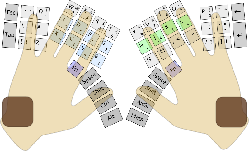
In total, it turned out that my fingers reach up to 50 keys, and it seems that all the necessary keys are in place (though not always on their own, if viewed from the point of view of traditional layouts). Is it enough to have 50 keys, considering that on traditional keyboards there are 104 keys (in extreme cases, 87, in the version without a block of numeric keys)? With the use of the Fn modifier, this becomes possible, because the combinations of letters and Fn are usually not used, and you can hang anything that does not fit on them, but for some reason you need, for example, arrows, Home, End, PgUp and PgDn.
Brown squares under the wrists denote soft lining.
Indicators? I do not use Caps Lock, there is no separate digital block, so I don’t need a NumLock, and for what many people need ScrollLock, they probably don’t even know. So sweep away the indicators.
The block of keys under the little finger is slightly embarrassing, if suddenly someone else decides to use my keyboard, his little finger can be shorter than my seven-octave one, so I decided to make the little finger under the little finger from the one shown in the figure to parallel to other columns of keys.
Another aspect is the natural position of the hands, which is rather closer to the vertical position of the palms than to the position of the palms down to which we are all accustomed. This is one of the reasons why I didn’t buy the Truly Ergonomic keyboard and didn’t calm down. This tends to make the keyboard split into two halves, like the Kinesis Freestyle and Ergodox with BlueCube, and tilted.
So, according to the plan, the keyboard is split, with a reduced number of keys, with a shifted block for thumbs, with vertical even columns, vertically shifted relative to each other, the left and right blocks are inclined (adjustable, because different sources advise the slope from 15 to 90 degrees relative to the vertical surface, and shifting adjustable blocks under the little fingers, without indicators.
Details
A short list of what you need:
- keyboard switches;
- caps on the switches;
- diodes (why are they needed - a little later);
- microcontroller, allowing the keyboard to be a USB device, and reading the state of the switches;
Pay
Since I do not evaluate the chance for error-free design of the printed circuit board from the first attempt for myself as extremely low, with LUT and photoresist, I decided to make the wiring for the price of the production for the order in unit volume - high. The material is textolite used in conventional printed circuit boards. A friend, fortunately, lay a few plates of fiberglass, which I borrowed. Chic material, for ease of use comparable only with the blue electrical tape.
Microcontroller
Despite my youthful enthusiasm about the bright future of ARM controllers, I nevertheless chose a device based on a more traditional AVR. Of the most suitable for this application, the Atmega32u4 was identified, with a 32KB ROM, a sufficient number of input / output ports operating in the slave USB device mode, and also able to communicate on I 2 C. The fact that the keyboard would be without a traditional printed circuit board led to the need take the controller on the remote board, and I chose the most compact - Teensy . There are a lot of options, even from the same manufacturer, and even there are domestic analogues , although for some reason they are more expensive .

Switches
The choice of keyboard switches consisted only between mechanical ones from Cherry, the brand known to many by keyboards, and numerous Chinese clones of the now unreleased Alps switches.
Cherry has two main switches, the low-profile Cherry ML , and the more commonly used MX , produced in the following main versions :
- black (linear pressing force, medium elasticity, not clicking);
- red (lined, light, not clicking), are popular in gaming keyboards;
- gray (tactile, elastic, not clicking);
- transparent (tactile, medium elastic, not clicking);
- green (tactile, medium elastic, snapping);
- blue (tactile, light, clicking);
- brown (tactile, light, snapping);
- white (tactile, medium elastic, moderately clicking).
Based on personal preference, I liked the transparent ones.
Switches are different way of installation. There is an option for mounting on a printed circuit board, and for mounting on an additional plate. The former have two additional columns for greater stability, and the latter requires an additional plate for stability. In this additional plate, you can click the first option.
There are many more modifications of MX, but this is one of those parts that are not so easy to buy, or not so cheap, especially in small quantities, and in not very popular versions - and even more so. On Ebay, they are sold for nearly $ 4 each, the choice for suppliers of electronic components is very small. It is remarkable that they organize group purchases on keyboard forums, one of which I fit into. Unfortunately, it was necessary to either wait or take what was, and I took the blue ones (choosing from red, brown and blue), in the version with installation on a printed circuit board.

Caps
Initially, I wanted to buy some old mechanical keyboard, remove the switches from it and remove the caps, but I didn’t find anything worthwhile.
Since buying a new one, choose one. A good choice for WASD Keyboards, I decided to try to take different keys, and took a set of 39 keys of the alphabet block, and two sets of color per sample, to which the keyboard dampers are also included to reduce the clicking effect (the clicking effect of caps on the board, and not internal flip switch effect). I also need keys of larger size, and I took a few keys, usually used as Tab (1.5x), Alt (1.25x) and Caps Lock (1.75x), in different colors.
Now mainly used cylindrical flasks, in which each row of keys has its own profile.
I didn’t have a single key from the digital series E in the sets:


Diodes
Diodes, namely 50 pcs. 1N4148 in the case of DO-35, which turned out to be easier and cheaper to buy with delivery from England than in local supermarkets selling electronic components.
"Lego for adults"
Details and tools.

Layout
Iron
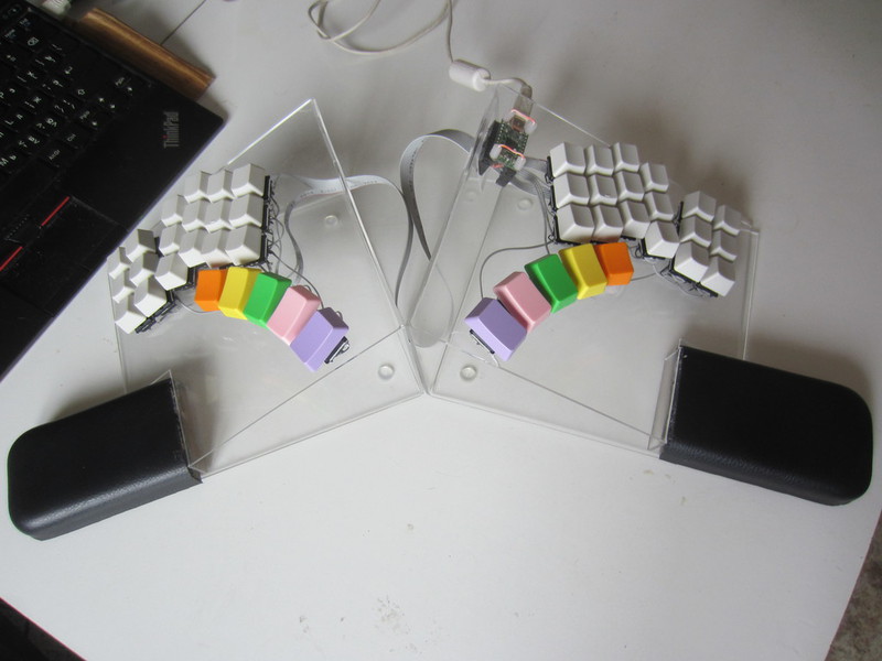
In order not to waste time, I decided to put together a mock-up and touch it, what could possibly come of all this, and not waste time if I suddenly don’t like this intermediate result. Here's what I got:

The hand (left, I decided to act on the principle of fitting shoes) is comfortable, reaches all the keys. Resolved, continue.
Microcontroller
Teensy comes with a wired flashing light. Surprisingly, when you connect it with a USB cable to the computer, the little diode really starts blinking. There is one more example for the site, called the “fast-moving light bulb,” I downloaded it and uploaded it to the device, and the light bulb actually began to flash faster. Filled the original - again slower. Well, quite well, the strobe can already be done.
Small swathes with example sources from a site called “USB keyboard”, and every 8 seconds a space character is printed on the screen, and when GND is closed with any of the inputs, two characters appear on the screen, indicating the port and foot number, for example B1. The current is miserable - 135µA. More good luck.
Theory
How do you connect 50 (and on conventional keyboards, more than double) keys to a microcontroller with 25 I / O ports, leaving a few for things like a mouse?
Everything is quite simple, you need to distribute the keys in rows and columns, forming a matrix. By applying voltage to column A, and removing this voltage from rows 2 and 3, one can understand that now the keys at the intersection of these rows and this column are in a depressed state. Voltage is applied to the speakers in turn. Thus, roughly speaking, I do not need the number of I / O ports equal to the number of keys, but rather a square root of this number, in my case 8x7, that is, 8 outputs and 7 inputs (or vice versa).
However, this method has one serious drawback, which is manifested in blocking and disappearing clicks:

This figure shows that when the keys W, E and D are pressed, and when the voltage is applied to column B, the false triggering of the key S occurs. Diodes are designed to fight this phenomenon:

Read more about this here .
In addition to this, the USB standard introduces a serious limitation to the printed input devices connected to it, to 6 simultaneously pressed (non-modifying) keys. Some manufacturers bypass this limitation by emulating the connection of multiple USB devices. Honestly, I came across this restriction only in my youth, when there was no money for a MIDI keyboard, but I wanted to play a fat chord. But so, note.
A slight pause for thought


At different moments it seemed to me that there were too many keys (yes, yes, no matter how funny it sounds with just 50 keys!). And when I ordered only 50 switches without any reserve, and when I tried to reach the extreme four keys on the layout with my little fingers, and when I began to think that the seventh column of keys would lead to the need to pull additional wire between the keyboard halves in addition to the cable. On top of that, these originally planned keys should have been located Escape, Tab, Backspace and Enter, which are already on the keys under your thumbs. Duplicate makes no sense. And if you already get used to the new keyboard, so right away, without the ways of retreat.
Scheme
The scheme is so simple that it doesn't even make much sense to draw it.

The columns and rows in the matrix correspond to the keys, the thumb block keys are the fourth row.
We supply voltage from the speaker to all incoming legs of the switches of this speaker. From the outgoing switch legs to the diode anode. We connect the outputs from the cathodes of all switches in a line, and connect them to the input of a line.
For the right half of the keyboard, 6 outputs and 4 inputs are required, on the left - 6 more outputs, and the inputs can be used the same. It turns out the matrix 12x4, so much as 18 inputs and outputs, which is somewhat uneconomical. I will use a 6 by 8 matrix, which is easy to imagine, as one half of the keyboard, located not on the left, but on the bottom of the other, for a total of 14 I / O ports.
It turns out that in the left half of the keyboard will need to lead 10 lived. The pin connectors I bought are just 10 lived, and they are exactly enough.
The legs on the controller can be in two modes: input or output. The input can be open, in this case, if it is not closed, it can make noise, and it is better to transfer it to the mode with the built-in pull-up resistor turned on, so that if it is not closed to ground, it will always be in state 1. Set the outputs By default, the state is 5V, and while reading a specific column, we lower it to 0V, so that when it is closed with an input, the latter changes to a state of 0, which means that the button is pressed. Such a connection option leads to a certain misunderstanding in the form of the fact that the current “flows” from the inputs to the outputs.
There are other connection options, where everything is more or less logical, but they provide additional external elements, such as one for all outputs or several external resistors (to save ports with reading through the ADC), but it seems to me that if there is a controller with sufficient the number of ports, he himself has to cope with how he has some leg closed, so - the easiest option, although at first glance and not the most understandable.
The legs of the microcontroller on Teensy are not all derived, and those that are derived - go to each other. From the “solid” ports there is only B. Partially bred - F (no legs F2, F3), D (two legs on the bottom end of the board, do not have their own legs, and two more are aligned with I 2 C, C (there are only legs C6 and C7).
On the microcontroller, we use the legs of PF0, PF1, PC6, PC7, PF4-PF7, we use the outputs, PB0-PB5 for the inputs (with a pull-up resistor). We leave the legs of PD0 and PD1 under I 2 C, which will come in handy later for connecting the mouse / trackpoint. We don’t touch the PD6 leg, because it is connected to an on-board LED that can be powered by the current applied to this leg and lower the voltage from 5V to ~ 1.7V.
Iron
Pay
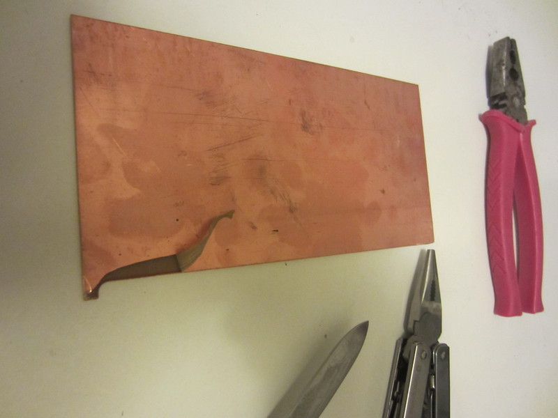
Textolite is intended for etching conductive tracks on it. Since this is not necessary in my case, the foil will have to be removed from it. This is not so easy to do, since it is much thicker and stronger than the one that we all used to remove from chocolate bars. It is difficult from the very beginning - to hook a corner of this foil, then, if you take it off with thick stripes, you have to apply a lot of effort, and if you thin it, it tries to break, and you have to look again for a corner. I was able to identify a fairly simple way: hook from the corner, and lead 1-1.5cm in a spiral to the center of the board.

Interesting patterns remain on the PCB, allowing you to understand exactly how the foil was removed.

I highly recommend wearing gloves, and removing the foil with pasatizhami, otherwise scratches are inevitable.
Drilling
I made a sketch of how the switches should be located on the board (boards, because it turns out at least 4 pieces, and for the best layout on the PCB as much as 6 pieces). In order for them to be fixed on it, the board needs to be drilled.For each switch, there are 7 holes, two of 0.8mm each, two of 1.2mm each, two of 1.6mm each, and one central 4mm.
Drilling immediately on the printout is not very convenient, so I made a stencil from the old aluminum back cover of the mobile phone:
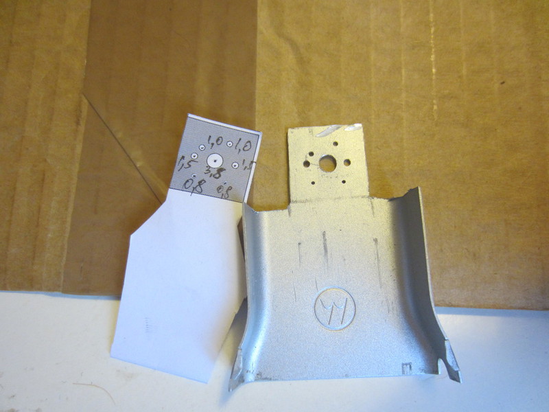
Cutting and drilling aluminum is not easy, it heats, flies in all directions, therefore I recommend using special safety glasses. As during other operations.
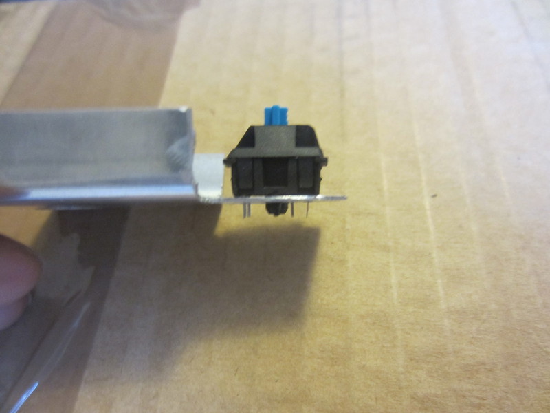
This is how the switch looks like it is inserted into the stencil.

Alas, the cam chuck of a drill is designed for drillings with a tail of maximum diameter 3.4mm, but the 3.5mm drill bit is quite stable. To drill a 4mm hole, they had to make several circular movements. I do not recommend repeating this.
Originally drilled on a wooden substrate, and somewhere on the honeycomb hole, the 0.8mm drill broke under the root, because the textolite shifted relative to the substrate at the moment when the drill was lowered. Later he drilled so that there was nothing under the tectolite.

It turned out one is not too pleasant thing associated with the switches. If they are stuffed into holes that are not exactly drilled out, it can be deformed, and its tactile properties change, to the extent that it does not click, and can even stick. Drill holes wider. Later, I decided to drill with a conventional drill and a 4mm drill, but still half of these large openings would have to be board so that the switches would enter without much effort.
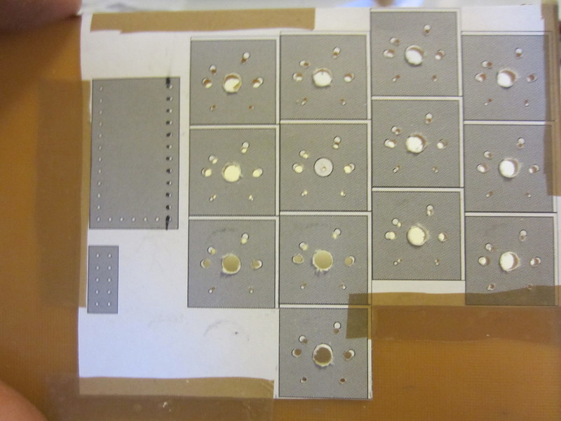
It turned out this:


Feels like - the switches sit in the board very tightly, do not stagger, everyone entered the board without much effort. After soldering sit tight. To be honest, a rather unexpected result for such handicraft work, is pleased with himself.
Despite the apparent unevenness of the hole lines in 2.54mm pitch, the microcontroller and the IDC connector stood up effortlessly and tightly:


Again diodes
There are two options, the first is to solder the diodes in a mounted manner, not the easiest option, considering how many wires will be soldered there. The second option is to disassemble the switches, and instead of the local wire, designed to facilitate the wiring of a single-layer printed circuit board, insert a diode. Yes, this is a definite work, but it should pay off by simplifying the mounted installation. There is a third, correct option, buying switches with a diode right away, but the latter, for some unknown reason, are far from popular, and there is no place to buy them except to order a large batch directly from Cherry.


Cutting
The boards need as much as 6 pieces. Theoretically, it was possible to make two, but 1) the size of the tectolite pieces does not allow 2) even if allowed, it would turn out to be not very economical 3) there is an opportunity to play the position of the boards relative to each other during the assembly.


Interboard connections
In order not to have to pull the wires between the keyboard halves, I used loops, similar to those used to connect hard disk drives to the motherboard, with only fewer wires, and IDC / BH connectors. Of course, it would be more correct to use a twisted pair, but I need more than 8 wires, and the 8P8C connector is also not too compact (and the 10P10C and 10-core twisted pair is not so easy to find). Another option would be to use the I / O port multiplexer on the I 2 C bus , but I decided to postpone this improvement.
By the way, IDC connectors angular and straight I got completely different. The straight line was not soldered in any way, and the legs fell out of it at the slightest heat, and the corner soldered well. Externally did not differ anything.

Soldering
I can say one thing about soldering - this is not my fad. Tyap-bluff, but it works.

Firmware
Attempt at writing
So, I got a piece of the keyboard, and it would be time to check if all this works as I expected.
A number of examples go to Teensy, including a USB HID (human interface device), in keyboard and mouse options. From the first of these examples, the firmware has grown.
In the original example, the calculation is based on the fact that the inputs with the switches are closed to the ground, and when the matrix is connected everything is a little different, voltage is periodically applied to a part of the legs, and during this period the condition of the other legs is read. In order for the legs to work as outputs, you need to transfer them to this mode.
In the general approximation, the order is as follows: we initialize the ports and USB; In the cycle, we alternately apply voltage to the outputs, read the inputs, if the value at the input corresponds to the key pressed, and in the previous reading cycle it was not pressed, we send the key code via USB.
I am not a big specialist in C, and when it comes to digging into macros, I’m getting a little lost, so the code can be a little awkward, but the general sense is to convey:
Let the reader forgive my habit of making comments in English.
Firmware code
 #include <avr / io.h>
#include <avr / pgmspace.h>
#include <avr / interrupt.h>
 #include <util / delay.h>
#include "usb_keyboard.h"

#define CPU_PRESCALE (n) (CLKPR = 0x80, CLKPR = (n))

uint8_t matrix [8] [8] = {
/ * B0 * / {KEY_TILDE, KEY_Q, 0, 0, KEY_W, KEY_E, KEY_R, KEY_T}, // Top row
/*B1*/ {KEY_SLASH, KEY_A, 0, 0, KEY_S, KEY_D, KEY_F, KEY_G}, // Home row
/*B2*/ {KEY_LEFT_BRACE, KEY_Z, 0, 0, KEY_X, KEY_C, KEY_V, KEY_B}, // Bottom row
/*B3*/ {0 /*Fn*/, KEY_ENTER, 0, 0, KEY_TAB, KEY_ESC, KEY_SPACE},

/*B6*/ {KEY_Y, KEY_U, 0, 0, KEY_I, KEY_O, KEY_P, KEY_EQUAL}, // Top row
/*B5*/ {KEY_H, KEY_J, 0, 0, KEY_K, KEY_L, KEY_SEMICOLON, KEY_QUOTE}, // Home row
/*B4*/ {KEY_N, KEY_M, 0, 0, KEY_COMMA, KEY_PERIOD, KEY_SLASH, KEY_RIGHT_BRACE}, // Bottom row
/*D7*/ {KEY_SPACE, KEY_ESC, 0, 0, KEY_TAB, KEY_ENTER, 0 /*Fn*/}
 };

 int main (void)
 {
  uint8_t state=0, prev_state[8] = {0xFF, 0xFF, 0xFF, 0xFF, 0xFF, 0xFF, 0xFF, 0xFF};

  setup_pins_and_usb();

  while (1) {
    // B0
    PORTB = 0b11111110;
    _delay_ms(5);
    state = PINF;
    read_row(state, prev_state[0], matrix[0]);
    prev_state[0] = state;
    // B1
    PORTB = 0b11111101;
    _delay_ms(5);
    state = PINF;
    read_row(state, prev_state[1], matrix[1]);
    prev_state[1] = state;
    // B2
    PORTB = 0b11111011;
    _delay_ms(5);
    state = PINF;
    read_row(state, prev_state[2], matrix[2]);
    prev_state[2] = state;
    // B3
    PORTB = 0b11110111;
    _delay_ms(5);
    state = PINF;
    read_row(state, prev_state[3], matrix[3]);
    prev_state[3] = state;

    // B6
    PORTB = 0b10111111;
    _delay_ms(5);
    state = PINF;
    read_row(state, prev_state[4], matrix[4]);
    prev_state[4] = state;
    // B5
    PORTB = 0b11011111;
    _delay_ms(5);
    state = PINF;
    read_row(state, prev_state[5], matrix[5]);
    prev_state[5] = state;
    // B4
    PORTB = 0b11101111;
    _delay_ms(5);
    state = PINF;
    read_row(state, prev_state[6], matrix[6]);
    prev_state[6] = state;
    PORTB = 0b11111111;
    // D7
    PORTD = 0b00000000;
    _delay_ms(5);
    state = PINF;
    read_row(state, prev_state[7], matrix[7]);
    prev_state[7] = state;
    PORTD = 0b10000000;
   }
 }

void read_row(uint8_t state, uint8_t prev_state, uint8_t keys[]) {
  uint8_t mask, i;

  mask = 1;
  for (i=0; i<8; i++) {
    if(((state & mask) >> i) == 0 && ((prev_state & mask) >> i) == 1 ) {
      usb_keyboard_press(keys[i], 0);
     }
    mask = mask << 1;
   }
 }

void setup_pins_and_usb() {
  // set for 16 MHz clock
  CPU_PRESCALE(0);

  // Configure PB0-PB6, PD7 as outputs, high state
  DDRB = 0b01111111;
  DDRD = 0b10000000;
  PORTB = 0b01111111;
  PORTD = 0b10000000;

  // Configure PF0, PF1, PF4-PF7 as inputs, pullup enabled
  DDRF = 0x00;
  PORTF = 0xFF;

  // Initialize the USB, and then wait for the host to set configuration.
  // If the Teensy is powered without a PC connected to the USB port,
  // this will wait forever.
  usb_init();
  while (!usb_configured()) /* wait */ ;

  // Wait an extra second for the PC's operating system to load drivers
  // and do whatever it does to actually be ready for input
  _delay_ms(1000);
 }
Checked - works. Luck.
Firmware firmware
You can continue to make a fuss here, but in the firmware lies no less subtleties than in the gland. And I got the idea to use ready-made firmware. From the network, the most noteworthy were two:
Clavis . Used in the same mod of the old Wyse WY-85 terminal keyboard. In principle, it looks quite customizable, but out of the box there are not enough of some features that are in the second firmware.
TMK Keyboard . Very firmware firmware, used in a dozen (if not dozens) of keyboard mods and homegrown keyboards. Out of the box has the following capabilities:
- layering layouts (you can use a single layer for additional useful characters, like a typographical hyphen, etc.);
- emulation of mouse movements using keys;
- can send system key codes: Power Down, Sleep, Wake Up, Volume Down / Up, Mute, Next / Prev track, Play, Stop and others;
- transfer of multiple simultaneous keystrokes (not limited to the USB limit of 6 keys);
- customizable to the smallest details;
- works with keyboard "tricks", namely, it can use the same physical keys for different purposes depending on the type of pressing;
- firmware debug console.
At first there was a problem with sticking keys, but by the time when I finished everything, the problem was already solved. My code can be found here. .
Layout
#define KEYMAP (\ K00, K01, K02, K03, K04, K05, K40, K41, K42, K43, K44, K45, \ K10, K11, K12, K13, K14, K15, K50, K51, K52, K53, K54, K55, \ K20, K21, K22, K23, K24, K25, K60, K61, K62, K63, K64, K65, \ T30, T31, T32, T33, T34, T70, T71, T72, T73, T74 ) {\ {KC _ ## K00, KC _ ## K01, KC _ ## K02, KC _ ## K03, KC _ ## K04, KC _ ## K05}, \ {KC _ ## K10, KC _ ## K11, KC _ ## K12, KC _ ## K13, KC _ ## K14, KC _ ## K15}, \ {KC _ ## K20, KC _ ## K21, KC _ ## K22, KC _ ## K23, KC _ ## K24, KC _ ## K25} , \ {KC_0, KC _ ## T30, KC _ ## T31, KC _ ## T32, KC _ ## T33, KC _ ## T34}, \ \ {KC _ ## K40, KC _ ## K41, KC _ ## K42, KC_ ## K43, KC _ ## K44, KC _ ## K45}, \ {KC _ ## K50, KC _ ## K51, KC _ ## K52, KC _ ## K53, KC _ ## K54, KC _ ## K55}, \ { KC _ ## K60, KC _ ## K61, KC _ ## K62, KC _ ## K63, KC _ ## K64, KC _ ## K65}, \ {KC _ ## T70, KC _ ## T71, KC _ ## T72, KC_ # # T73, KC _ ## T74, KC_0} \} static const uint8_t PROGMEM keymaps [] [MATRIX_ROWS] [MATRIX_COLS] = {/ ** Layer 0: (lowercase char) * * `qwertyuiop = * \ asdfghjkl; '* [zxcvbnm,. /] * / KEYMAP (\ GRV, Q, W, E, R, T, Y, U, I, O, P, EQL, \ SLSH, A, S, D, F, G, H, J, K, L, SCLN, QUOT, \ LBRC, Z, X, C, V, B, N, M, COMM, DOT, BSLS, RBRC, \ FN0, FN1, FN2, FN3, FN4, FN9, FN8, FN7, FN6, FN5), / ** Layer 1: (symbols and navigation) * * 1 2 3 4 5 6 7 8 9 0 - * ↰ ↑ ↳ ⤒ ← ↓ ↑ → * ← ↓ → ⤓ * / KEYMAP (\ NO, 1, 2, 3, 4, 5, 6, 7, 8, 9, 0, MINS, \ NO, NO, PGUP, UP, PGDN, HOME, LEFT, DOWN, UP, RGHT, SCLN, QUOT, \ NO, NO, LEFT, DOWN, RGHT, END, NO, NO, NO, NO, NO, NO, \ FN0, FN1, FN2, FN3, FN4, FN9, FN8, FN7, FN6, FN5)}; / * * Fn action definition * / // TODO: use [1] = KEYMAP (...) to prevent from changing the index of element? static const uint16_t PROGMEM fn_actions [] = {ACTION_LAYER_TAP_KEY (1, KC_SPC), // FN0 = L1 symbols ACTION_MODS_TAP_KEY (MOD_LSFT, KD_KH_CH_CH_CH_CF_KC_SPC), // FN1 = Shift with tap Space ACTION_MODS_TKH tap Escape ACTION_MODS_TAP_KEY (MOD_LALT, KC_TAB), // FN3 = Alt with tap Tab ACTION_MODS_TAP_KEY (MOD_LGUI, KC_DEL), // FN4 = Means with Tap ), // FN6 = Shift with tap Enter ACTION_MODS_TAP_KEY (MOD_RCTL, KC_TICT), // FN7 = Ctrl with tap Backspace ACTION_MODS_TAP_KEY (MOD_RALT, KC_RALT), // FN8 = Ctrl with tap Backspace ACTION_MTPST (KC_RALT), // FN8 = Ctrl with tap Backspace ACTION_MTPST_KAP_KEY (MOD_RALT) Meta with tap Tab}; Matrix
 / * Column pin configuration
  * col: 0 1 2 3 4 5
  * pin: F0 F1 F4 F5 F6 F7
  * /
 static void init_cols (void)
 {
     DDRF = 0b00000000;
     PORTF = 0b11111111;
 }

 static matrix_row_t read_cols (void)
 {
     return (PINF & (1 << 0)? 0: (1 << 0)) |
            (PINF & (1 << 1)? 0: (1 << 1)) |
            (PINF & (1 << 4)? 0: (1 << 2)) |
            (PINF & (1 << 5)? 0: (1 << 3)) |
            (PINF & (1 << 6)? 0: (1 << 4)) |
            (PINF & (1 << 7)? 0: (1 << 5));
 }

 / * Row pin configuration
  * row: 0 1 2 3 4 5 6 7
  * pin: B0 B1 B2 B3 B6 B5 B4 D7
  * /
 static void unselect_rows (void)
 {
     // Hi-Z (DDR: 0, PORT: 0) to unselect
     DDRB = 0b01111111;
     DDRD = 0b10000000;
     PORTB = 0b01111111;
     PORTD = 0b10000000;
 }

 static void select_row (uint8_t row)
 {
     // Output low (DDR: 1, PORT: 0) to select
     switch (row) {
         case 0: PORTB & = ~ (1 << 0);  break;
         case 1: PORTB & = ~ (1 << 1);  break;
         case 2: PORTB & = ~ (1 << 2);  break;
         case 3: PORTB & = ~ (1 << 3);  break;
         case 4: PORTB & = ~ (1 << 6);  break;
         case 5: PORTB & = ~ (1 << 5);  break;
         case 6: PORTB & = ~ (1 << 4);  break;
         case 7: PORTD & = ~ (1 << 7);  break;
     }
 }
Another pause for thought
I came across another very interesting copy of a homemade keyboard, which differs from the others in its simplicity of design, namely the plate on which the switches are mounted.
Not only are the contacts sticking up from the bottom of the board, they are still all hung with wires. Need something like bottom cap. The pieces of the board are scattered, and it is not an easy task to fasten them together securely and firmly on the posts I have bought for connecting the printed circuit boards and screws. It would be ideal if it also served as a stand, giving the whole structure the desired slope.
A network search showed that plexiglass has a number of unique qualities, such as low weight, plasticity when heated to 140 degrees, the possibility of cutting with a laser and a cutting machine, drilling, and also a very low cost.
It seems that the textolite idea was the wrong engineering solution, and I bought a 1.5mm thick Plexiglas sheet.

Everything else, I tried it on, and it seemed to me unnecessarily large distance between the buttons under my thumbs, I decided to slightly reduce it, literally move a millimeter, but it will bring the far key closer to almost half a centimeter. I tried to use the keys of the standard 1x size, it would be possible to compact a little more with them, but it was not so convenient to press them with the side surface of the thumb.

Housing
Many have already ceased to notice what the price tags and stands are made for the goods in the store, and they are usually made just from this very plexiglass. There are two ways of bending, the first is heating with a blowtorch along the bend line, and bending along a wooden ruler. It is fraught with bubbles in the material, fire, and, above all, low accuracy. The second method is bending under its own weight along the heated wire. It is a suitable way for a fairly thin plexiglass.
Flexion test
I needed: a meter of nichrome wire, four screws, a board. Some guides on the Internet say that the nichrome wire stretches when heated, and it is imperative to use a stretching core. According to my humble estimates, according to Wikipedia, the increase in the volume of nichrome is slightly less than a millimeter when heated to 200'C and the length of the wire is 30 cm.
Before bending it is very important not to forget to remove the protective film from the Plexiglas.

Attempts to heat the wire with a ceramic element of a soldering iron failed, as well as a universal power supply for 1A, turned on for 1.5V. The resistance of a wire section of 30 cm length is about 1 Ohm, and at a current of 1A, a power of 1W is obtained, which, according to calculations, can heat the wire to 150'C for 500 seconds, and only if it does not cool down, but it will.
I need something more powerful, and I took the old AT power supply and connected the ground and 5V wires to the ends. The effect did not take long, the wire very quickly warmed to a temperature when a drop of water on it instantaneously evaporated.

The wire is still stretched, and it is so strong that it sags a couple of millimeters, which makes the fold line uneven, and on the sides it is slightly better attached to the sheet being bent, heats it more, even melting slightly. For the test, of course, it will go, and those “stretchers” in the form of joiner dowels are enough, but to make it beautiful and smooth, you need something more reliable.


The design turns out strong, it bends very weakly, the laptop sits on it like a glove.

Wrist rest
I did not find an analogue of English wrist rest in Russian, so let it be “emphasis”, although it is understood that this is the thing on which the brush rests when the wrists lie on it. I got from the keyboard pad-arm my wife bought (worthy of a separate post), there was an emphasis for the keyboard, and for the mouse. The latter did not use his wife’s demand, and therefore I did not fail to use it for my own purposes.

Since the emphasis is one and there are two halves of the keyboard, it will have to be cut in half. Better yet, remove all scratching smooth surface staples.


And it is convenient to connect to the structure.

The hand on this is comfortable, and you can find several positions in which it is completely relaxed.
Inside - two layers of the gel, the inner is harder, and outside, under a layer of imitation leather, softer, and even slightly sticky.
That the design did not slide on a table, I bought the special glued legs.

Cutting through
In order for the switches to stand on plexiglass, it is necessary to make a slot in it for them, and snap it. The cuts are made on proprietary equipment, but this is done quickly and is not expensive.


In the first version of the case of plexiglass, I made the holes a little larger than necessary, by about 0.3mm, and the switches slightly walked horizontally. Version two gave me the opportunity to slightly adjust the key layout under my thumbs, not to use engraving (at the engraving site, the material becomes thinner by as much as a third), and actually reduce the size of the holes.
With version two there was the following problem. On the bottom (second version), the switches do not click (such small things are above and below in the middle of each switch). At first I thought that I had cut the holes too much, but it turned out (!!!) that the 1.5mm acrylic sheet thickness can reach 1.8mm, and that the switches are designed for 1.5-1.68mm. I did not expect such a setup, but I was lucky that I ordered four “halves” at once, and two of them turned out to be of normal thickness, and the switches clicked on them as well as possible.


Softeners
Many people remember that mechanical keys make a lot of noise. This is connected not only with the operation of the mechanism, but also with the fact that after the switch is triggered with a strong and quick press, the key goes all the way to the stop, and knocks on this stop. To level this effect, there are special rubber rings that prevent contact. There are many types of them, including in my set there were 3 different types.

I decided to try everything, albeit limited in quantity. Black went to the "home" line, red - up, blue - down. Color keys and extreme columns of the ringlets did not get.

Controller mount
I had SP-3 interboard racks, and I tried to drill holes in plexiglass, but somehow they didn’t enter the hole even 5mm, and my exact drilling limit was 3.5mm, so I bit off their fasteners, drilled them along the axis, and attached the controller in just such a simple way, passing the wires of the twisted pair round.


Keeps on just fine.
Yes, of course I had to rewrite almost everything again, but having already some experience in this matter is already a little easier and faster. I slightly changed the assignment of the inputs-outputs, so that it would be easier with loops and IDC connectors (PF0, PF1, PF4-PF7 for outputs, PB0-PB3 for inputs of the left half, PB4-PB6, PD7 for inputs of the right half).


Flexion
Trial bending was not so bad in principle, but I wanted to make the bend line more equal, and I attached a spring removed from the door lock with a latch.


The inscriptions on the keys
Despite the fact that with a specific layout, I have not yet decided whether to use QWERTY, Colemak , Workman-P or whatever, but I have already chosen the font for the keys, this is Neuropol Nova from Typodermic. Selected because of futuristic, excellent design and the ability to make a stencil. Everything else, the author kindly agreed to use this commercial font for my purposes. The stencil is cut in the same place as plexiglass, and looks like this:

Layout
The current layout:
` qwertyuiop =
\ asdfghjkl ; '
[ zxcvbnm , . / ]
Russian letters are on the same keys as usual. The arrangement is standard, only the letter X has moved left to the left of I.
A number of modifiers (color) includes both modifying keys and ordinary ones. Modifiers work when pressed in combination, and when pressed once - the usual.
Single:
Spc Spc Esc Tab Del Tab AGr Bsp Ent Ent
Combination:
Lr1 Sft Ctl Alt Met Met AGr Ctl Sft Lr1
The second layer works in combination with red keys. The shooter, in my opinion, they even bust. Two options, for Vim fans - on the right (hjkl), and for WASD fans - on the left (dxcv actually).
1 2 3 4 5 6 7 8 9 0 -
↰ ↑ ↳ ⤒ ← ↓ ↑ →
← ↓ → ⤓
Results
Labor costs
Soon the topic is read, but it's not done soon.
If I had originally designed the design correctly, then in principle everything would take 10 hours. And so - two months to wait for some details, and another three months to build and refine all of this.
Finance
| Detail | Price |
|---|---|
| Teensy 2.0 microcontroller with legs | 780 |
| Cherry MX MX1A-E1JW Switches (Blue) | 1110 |
| Switch caps | 900 |
| Plexiglass | 150 |
| Cutting plexiglass | 350 |
Total: 3290 rubles.
I did not include such trifles as solder, wires, cable, plugs and diodes. I got the last ones very inexpensively, despite the expensive delivery, but if you smudge by the total amount ordered, you get something like 25 kopecks per piece at a store price of 6 rubles.
I got a free wrist stand, you can buy it for about $ 20.
I spent quite a lot on tools, but this will come in handy more than once. Some inexpensive ones (tweezers with heat-resistant plastic levers, which immediately melted at 200'C, a magnifying glass through which nothing can be seen, nippers that do not bite very much) were cheap, but served for a very short time.
Impressions
While typing on this keyboard is not so much. Surely I will find something to improve in the layout. In general, it is convenient, even very.
I foresee comments like "what about the xxxx key?". Only two layers are involved in my tmk_keyboard modification. You can add at least 30 more, and stuff all possible keys there.
For comments like “how will you press the xxx + yyy + zzz keyboard shortcuts?” I can answer that I specifically chose software not to torture my fingers (Linux, Awesome, Vim, Chromium + Vimium, Zathura). The most difficult combination of those that I use is Ctrl + Meta + [1-9], combining several virtual desktops into the current one. Now it works by pressing orange, green, lilac and pressing the number on the top row, it’s not very convenient, but I’ll definitely figure out how to do it easier.
Improvements that I want to make in version 2
Found a great I / O port expander NXP PCF8574AP in a DIP package. It is possible to replace the interboard cable with a thin four-core wire. I do not understand yet whether it is worth contacting I 2 C, according to rumors, the protocol is very slow, and a lot of time in the work of the firmware is spent on it. As an option - use shift registers 74HC164 and 74HC165.
There is a strong desire to replace Teensy with a bare AVR with the number of inputs and outputs sufficient for one half of the keyboard, and entrust the other half to PCFs. There is another option to make on the basis of a microcontroller from Microchip, PIC18F25K50, it is even cheaper, and among other things, it does not need external quartz to work with USB.
Make a printed circuit board, so that there is no this mounting, preferably thin and bending. Ideally, all components, such as a controller, diodes, a capacitor, and a programming button, are already soldered onto it.
Add a trackpoint on the Hall sensor, preferably between the HJNM keys, and three buttons under the mouse (it is possible to use the keyboard keys). I still do not understand where it will be convenient for the hands to find them.
Try transparent or red (after this note here) switches Cherry MX.
Make a case of 1.5mm plywood instead of plexiglass. Not so beautiful, but. Plywood is easy to work, less fragile. When properly treated, it is durable and resistant to moisture. It is harder to bend, but with such a thickness should not be so hard. On top of that, you can make the construction of several sheets, making slots and pins, so that it can be assembled, disassembled, on the principle of Lego. There is confidence that the thickness of the plywood does not walk on the area of the sheet by + 20% in contrast to the Plexiglas.
Make an inexpensive, adjustable in position and with a mount for both halves of the keyboard arm-arm mounted on a flat surface.
PS
And yes, of course, how could I forget!

Source: https://habr.com/ru/post/177347/
All Articles