We make a video surveillance system
System description
Standard video intercoms have known limitations on picture quality and viewing angle. In addition, video intercoms, as a rule, do not perform video archiving and do not support viewing video by external devices. As an addition to the video intercom, the author has designed and implemented this system privately.
The system is an analogue of a video eye connected to a TV set, which archives video and supports viewing video via a local network (LAN or Wi-Fi). The main elements of the system are: IP camera, switch with PoE support, nettop, Wi-Fi router. The software installed on the nettop provides:
- viewing video from an IP camera on a TV connected to a nettop via HDMI;
- archiving video from an IP camera to a nettop hard drive (1 hour of video requires about 1.3 GB);
- viewing video from an IP camera on devices connected to the nettop, as to a web server (works with any browser);
- view video from IP-camera on devices connected to the nettop, as a DLNA-server.
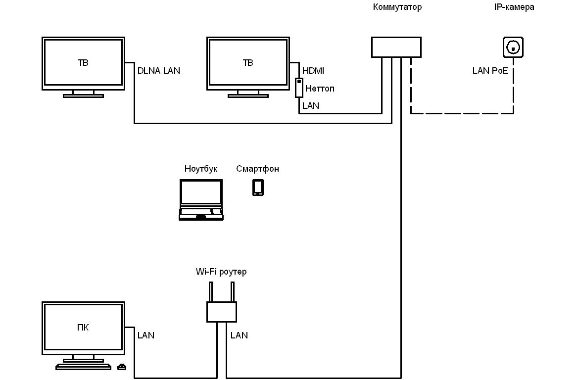
Block diagram of the system:
')
Hardware
The following main hardware was used to build the system:
- Hikvision DS-2CD7164-E IP camera;
- Switch with PoE D-Link DGS-1008P support (8 ports, 4 of them with PoE support);
- UTP 5e cable for external installation;
- Nettop ASUS EeeBox EB1021;
- Wireless keyboard with touchpad Logitech K400;
- ZyXEL Keenetic Giga Wi-Fi router (4 LAN ports, 1 WAN port, 2 USB ports, Wi-Fi).
The used IP-camera has a high sensitivity (at dusk or in the presence of snow it continues to work in color mode), however, additional lighting is required to get a high-quality picture at night. Otherwise, the picture is not informative (the contrast of the image depends on the device used for viewing):

Wi-Fi router is installed at the floor level on the third floor of a private house. On the second floor, under the premises of the Wi-Fi router, the signal is stable. However, the signal loses stability beyond the main brick wall. On the first floor, under the Wi-Fi router room, the signal is steady within a radius of about 3 meters from the Wi-Fi router installation site.
Software
When building the system, the following main software was used (installed on a nettop):
- ipc preview (viewing, archiving, web-server);
- serviio (DLNA server).
Nettop running the operating system Microsoft Windows 7 (64-bit).
The built-in web server of the IP camera, the standard Hikvision software and the specialized Trassir software did not meet the system requirements due to problems with video archiving, a complicated interface and a hard link to the platform on which the video is viewed. Therefore, especially for this system, the author has developed an ipc preview application that provides direct video archiving, has a simple interface and allows you to watch videos with any browser. This software is implemented in C ++ in the Borland C ++ Builder environment and is distributed with source code.
ipc preview receives main stream from an IP camera (1280 x 960, 25 fps, 3072 kbps max). The stream is displayed, archived and broadcast by the web server as a JPEG sequence or MJPEG stream. The resolution and quality of the broadcast is indicated by the client when the resource is opened. For a JPEG sequence, the frame rate is defined in the resource code. For the MJPEG stream, the frame rate is defined in the web server settings. The default frame rate is 2 fps.
serviio receives a sub stream (704 x 576, 12 fps, 192 kbps max) from the IP camera. The link to the stream is of the form rtsp: // admin: 12345@192.0.0.64/h264/ch1/sub/av_stream. The stream is broadcast by a DLNA server. Negative points noted when using a DLNA server:
- the resolution and frame rate of the main stream were too large for the connected TV;
- the stream opening procedure does not differ in convenience, since the connected TV does not allow assigning a key on the remote control to the stream;
- when you open a stream on the TV a brief message appears about the absence of an audio stream.
CPU load nettop is about 40%.
Mating devices
The function of viewing video from an IP camera was tested on the following devices:
- TV (HDMI: nettop -> TV);
- TV (DLNA LAN: nettop-> switch-> TV);
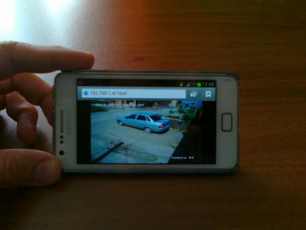
- Smartphone (Wi-Fi: nettop-> switch-> Wi-Fi router-> smartphone);
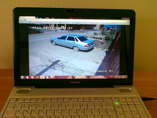
- Laptop (Wi-Fi: nettop-> switch-> Wi-Fi router-> laptop);
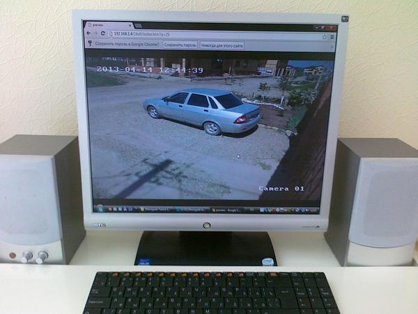
- PC (LAN: nettop-> switch-> Wi-Fi router-> PC).
Video viewing on a smartphone, laptop and PC is carried out using the browser installed on the device.
You can remotely view video over the Internet using a browser (a nettop connection to the Internet is required, a static or dynamic IP address or a virtual LAN, for example, using the hamachi program).
Issue price
The cost of the system was about 1 000 USD. Of them:
- IP camera - about 300 USD;
- switchboard - about 130 USD;
- nettop - about 460 USD;
- Wi-Fi router - about 100 USD.
It should be noted that in the described system nettop and Wi-Fi router are actively used as a universal media player and for distributing the Internet to mobile devices, respectively. Thus, the cost of these components can be excluded from the total cost of the system. If the system is not planned to be expanded, a direct connection of the IP camera to the Wi-Fi router is possible via the PoE injector (about 50 USD). In this case, the cost of the system will be determined by the cost of the IP camera and will be about 350 USD.
Photo report
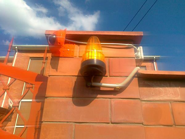
IP camera (upper right corner of the gate, painted in the color of the gate):

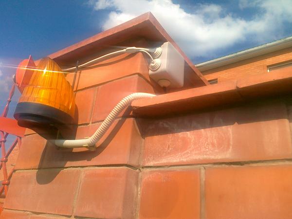
IP camera - near view:

Mounting IP-cameras (bent corner, bending angle is calculated depending on the camera angle):
Box for connecting the IP camera to the network (the power supply hole is false, all holes are sealed):
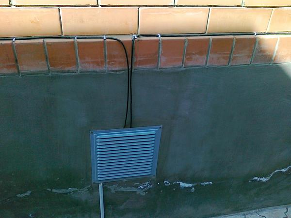
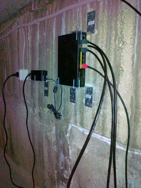
Cable entry point in the basement (cables: from the bottom - from the IP camera, on the left - to the Wi-Fi router, on the right - to the nettop):
Fixing the switch in the basement (standing on the corners with restrictive screws):
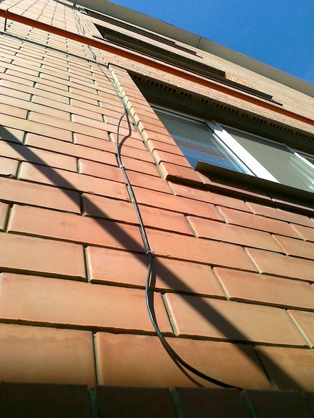
Attaching the cable to the Wi-Fi router (the vertical section hangs freely, there were no problems with wind load and icing):
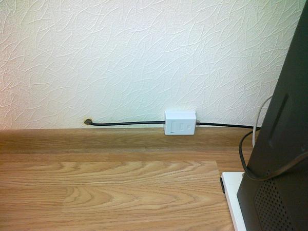
The cable entry point to the Wi-Fi router room (the cable is firmly fixed in the hole with a rubber stopper, the hole is sealed, the end of the cable is cut in the socket, an internal cable is laid from the socket to the Wi-Fi router):
Wi-Fi router (cables: left - from the switch, right - to the PC):

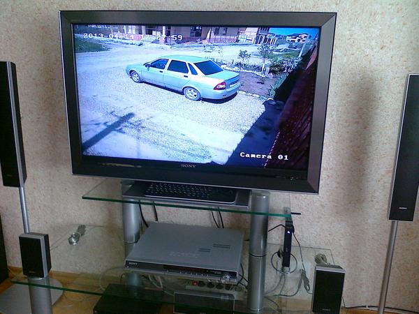
TV connected to nettop via HDMI:
Smartphone connected to a web server via Wi-Fi:
Laptop connected to a web server via Wi-Fi:
PC connected to a web server via LAN:
Source: https://habr.com/ru/post/177071/
All Articles