How to run a program without an operating system: part 3: Graphics

In this part we will try to do the “impossible”: learn how to use a graphic display without an operating system. In fact, this is not an easy task, especially when working in 32-bit protected mode, and especially if you want to use a decent screen resolution and not 320x200x8. But everything is in order: if we want graphics - it means you need to work with a video card.
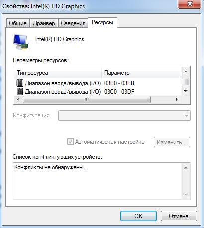
Modern graphics cards are practically full-fledged computers that are as powerful as the main ones: here you can decode MPEG2 as 1080p, support 3D graphics and shaders, technologies like CUDA, and much more. It all looks very difficult. On the other hand, the video card is just another PCI device, the same as the rest. We even “found” this device in the previous article with the device class number 0x03 (class_name = graphics adapter) . As with any device, a video card device can be operated using I / O ports or MMIO memory areas, and the video card itself can use DMA and interrupts to interact with the main processor. If you look at the range of I / O ports that are available for video cards, we see that it is allocated less than 50 bytes - not so much considering the enormous functionality that modern video cards have.
')
According to the VGA standard, two ranges of input / output ports will be used for working with a video card: 0x03B0-0x03BB and 0x3C0-0x3DF . In addition to these ranges, there is also a range of video memory ( 0xA0000-0xBFFFF ) displayed in the main memory.
Video memory is the representation of a graphic screen in the form of conventional memory. It turns out that to draw a pixel or a character on the screen, you need to write bytes in this memory range.
Since there is a standard to which modern video cards correspond, it is expected that with the help of the standard it will be possible to use a video card without going into details of its implementation.
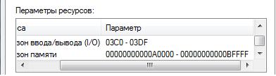
Unfortunately, there is one thing: VGA is an old standard and is designed to use simple graphic displays with a small, by modern standards, screen resolution. The standard defines a couple of dozens of different graphic and text modes (you can see everything here ), among which the “coolest” are: 320x200 in 256 colors and 640x480 in 16 colors. In this case, the standard includes only the functions of switching modes and functions for working with the palette. And where are the normal screen resolutions: 1920x1080 24 bits, or at least 800x600 24 bits? Where is the support for MPEG2 graphics? Where is 3D graphics? In the VGA standard this is not. About the graphics modes, you can still say that they are included in the SVGA standard, which is handled through the BIOS VBE extensions, which will be discussed further. And 3D, MPEG2, CUDA and other fashionable chips are supported by each video card manufacturer in their own way. The limiting screen resolution of 640x480 in the VGA standard, in addition to calculating the old displays, is determined by the video memory size: only 128 kilobytes (to work with a higher resolution, much more space is needed: 1920x1080 24bit - this is more than 6Mb). It means that there is still a large video memory area, and modern video cards have such an area:

One of the above ranges is used as the Linear Frame Buffer (LFB) - also the video memory. The second address range is used to display hundreds of registers and bit fields that are used to configure the video card. Moreover, the set of registers and the ways of working with them are unique not only for each video card manufacturer - they can differ significantly between the series and even the models of one manufacturer, and all this is necessary to ensure the operation of CUDA, MPEG2, 3D, ... Source codes of all graphic Linux drivers take up more than 8 megabytes:

Here is an example of a video card driver for one of the manufacturers:
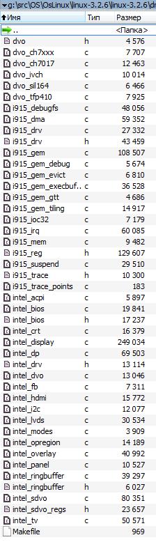
The rest contain even more code. And this is without the additional Linux libraries that are used in the drivers.
So, to provide support for 3D or streaming video, you need a lot of work. As the saying goes: if you have another life to spend, then ...
However, in this article we will focus on simply turning on a decent graphics mode and drawing something beautiful in it: for example, a fractal. Let's see how easy it is.
Let's start with the fact that decent graphics modes belong to the SVGA standard and are available for inclusion through the BIOS VBE extension (VESA BIOS Extension). VBE is a BIOS extension whose code is located on the video card itself and allows you to work with it. The standard of extensions VBE includes several functions that can be used:
1. Getting information about the graphics device. Is VESA supported, the amount of video memory on a video card, and so on.
2. Getting information about it by the mode number: screen resolution, pointer to LFB and bit depth.
3. Turn on the video mode by its number.
4. Turning on the bank for video mode by bank number, about them below.
5. Other functions including palette control, which is needed for 8-bit modes.
Full specifications can be found here . We briefly describe what you have to work with.
All modes supported by the video card are numbered in order from 0x000 to 0x1FF. Not all numbers are occupied and not all numbers after 0x100 have the exact value of the screen resolution in the standard: thus, the number still needs to be found at the required screen resolution. Mode numbers up to 0x100 are defined by the VGA standard and completely coincide with it. LFB - Linear Frame Buffer, is an area of video memory designed for large screen resolutions (usually it is located outside the RAM, but up to 4GB).
Without LFB, the standard video memory area from 0xA0000 to 0xC0000 is used to work with all graphics modes. In this case, the “banks” mode will be used. The whole screen is divided into numbered parts (banks) and at each moment of time the video memory area points to one of such parts. That is, before you draw a pixel on the screen, you will need to set the bank number, then draw a pixel, referring to the video memory. Thus, the same memory area can be reused to work with different areas on the display.

Using LFB is simpler and faster because you don’t need to switch anything and the entire display is displayed in the LFB. Video memory in LFB is organized in a linear fashion: the counting of pixels begins line by line from the upper left corner of the screen. Each pixel is represented by one, two, three or four bytes, depending on the bit depth of the current graphics mode. The bytes are located in a row and the pixel color is encoded in them. The simplest and most decent modes are 32-bit and 24-bit (three and four byte). In these modes, each color channel (Red, Green, Blue) is represented by the 1st byte. In 32-bit mode, another byte is reserved and not used (we can say that it is used for alignment). Another feature with LFB: as standard, to enable LFB in the mode number you need to set one more bit: mode_number | 0x4000.

Thus, using function number 2 (in the list above), you can find the mode number with LFB and enable it with function number 3. Then you can draw on the screen by simply writing down the Baitics with RGB values at the desired offset in the LFB buffer.
So far, everything looks promising, but VBE is a BIOS extension and it is a 16-bit code for Real-Mode that processes a specific BIOS function (in our case, 10h). It turns out that you need to use VBE (16-bit Real Mode) from the usual 32-bit Protected Mode, which we received in the previous article. There are three ways to do this:
1. Switch to Real Mode, perform the necessary actions, go back to Protected Mode. It is necessary to write transition functions between modes, save the state of the processor, and, in general, interrupts must also be correctly processed.
2. Use the VBE extension through a 16-bit interface from Protected Mode. To do this, you need to configure descriptor tables, create a call gate, compile a 16-bit code, and configure another additional structure according to the VBE standard. It is also not very convenient, besides not all video cards support this extension.
3. Use the 16-bit emulator Real Mode, which works in Protected Mode. The only limitation of this emulator is that it will be difficult to write interrupt handlers for the video card itself, but we don’t need it, because all VBE functions do not use video card interrupts.
The third way is the easiest, because you can take a ready-made x86emu emulator (simple and well-portable) and use it to call VBE functions.
Of course, we will have to work, but for a relatively small number of actions we will be able to assemble a program that on any modern video card can, without an operating system , turn on the graphics mode and draw a fractal. So far without shaders and 3D but, but the graphics.
! IMPORTANT! : All further actions can be successfully carried out only after successful completion of all 6 steps from the first part of the article “How to run a program without an operating system”
Our plan:
1. Add a few functions in common that we need for x86emu and drawing fractals.
2. Port x86emu.
3. Write a few functions to work with VBE.
4. Write the function of drawing a fractal.
5. All merge and run.
Let's get started
Step 1. We supplement common standard functions.
First you need to add a few functions to work with 64-bit numbers. They will need gcc to compile x86emu.
1. Add the following files to the common folder: udivdi3.c , umoddi3.c , moddi3.c , qdivrem.c , divdi3.c . They can be taken here .
2. Next you need to add another file quad.h to include. It can also be obtained from www.openbsd.org/cgi-bin/cvsweb/src/lib/libc/quad . In it you need to replace the lines:
#include <sys/types.h> #if !defined(_KERNEL) && !defined(_STANDALONE) #include <limits.h> #else #include <sys/limits.h> #endif on the lines:
#include “types.h” 3. Now, download the newlib library. It will be needed for one more function. From the library sources, copy the file newlib-2.0.0 \ newlib \ libm \ math \ s_floor.c to the common folder. We replace the line in it:
#include "fdlibm.h" per line:
#include "types.h" 4. You also need to add the setjmp / longjmp functions. The x86emu emulator uses these functions to handle errors. The implementation of these functions is given below; it was created based on the implementation from newlib, but was slightly simplified. The function allows you to save the state of the processor, and then restore it. Essentially similar to the manual implementation of C ++ exceptions. In order for these functions to appear in our code, you need to create a file setjmp.s in common with the following content (a little simple assembler):
.globl setjmp setjmp: movl 4(%esp),%ecx movl 4(%ebp), %edx movl %edx, 0(%ecx) movl %ebx, 4(%ecx) addl $4,%ebp movl %ebp, 8(%ecx) subl $4,%ebp movl (%ebp),%edx movl %edx,12(%ecx) movl %esi,16(%ecx) movl %edi,20(%ecx) movl %eax,24(%ecx) xorl %eax,%eax ret .globl longjmp longjmp: movl 4(%esp),%edx movl 8(%esp),%eax movl 0(%edx),%ecx movl 4(%edx),%ebx movl 8(%edx),%esp movl 12(%edx),%ebp movl 16(%edx),%esi movl 20(%edx),%edi testl %eax,%eax jnz 1f incl %eax 1: movl %ecx,0(%esp) ret The assembler code simply saves the registers in a certain order, and then restores them.
5. Now you need to declare the functions for C. To do this, create a file setjmp.h in include with the following content:
#ifndef _SETJMP_H_ #define _SETJMP_H_ #define _JBLEN 10 typedef long jmp_buf[_JBLEN]; #ifdef __cplusplus extern "C" { #endif int setjmp (jmp_buf); void longjmp (jmp_buf, int); #ifdef __cplusplus } #endif #endif 6. Another important set of functions that is required is the functions of working with strings and memory (memset, strlen, etc.). These functions are ready to be taken from bitvisor , so you need to download the source of this hypervisor. From these sources, copy the file c ore \ string.s in common. In it we replace the line:
.include "longmode.h" per line:
l
ongmode = 0 7. Next, you need to copy the file include \ core \ string.h into include from bitvisor. In it, replace the line:
#include <core/types.h> per line:
#include "types.h" 8. The last thing you need is the functions of working with I / O ports. To do this, add the io.h file to the include directory, which can be taken without any changes from the same bitvisor project (in the project sources, it is located in include \ io.h).
9. In order for everything to be copied, we replace the contents of include \ types.h with the following:
#ifndef _TYPES_H #define _TYPES_H #define NULL 0 typedef unsigned int size_t; typedef unsigned long ulong; typedef unsigned long u32; typedef unsigned short u16; typedef unsigned char u8; typedef unsigned long long uint64_t; typedef unsigned long long u_int64_t; typedef unsigned long uint32_t; typedef unsigned long u_int32_t; typedef unsigned short uint16_t; typedef unsigned short u_int16_t; typedef unsigned char uint8_t; typedef unsigned char u_int8_t; typedef long __int32_t; typedef unsigned long __uint32_t; typedef unsigned long long u_quad_t; /* quads */ typedef long long quad_t; typedef quad_t * qaddr_t; typedef unsigned long u_int; typedef unsigned long uint; typedef long long int64_t; typedef long int32_t; typedef short int16_t; typedef char int8_t; #define _QUAD_HIGHWORD 1 #define _QUAD_LOWWORD 0 #define __BEGIN_DECLS #define __END_DECLS #define __dead #define __far #define __HI(x) *(1+(int*)&x) #define __LO(x) *(int*)&x #define __P(a) a #define CHAR_BIT 8 /* max # of bits in a "char" */ #define EXTRACT_WORDS(i0, i1, x) \ i0 = __HI(x); \ i1 = __LO(x); #define INSERT_WORDS(x, i0, i1) \ __HI(x) = i0; \ __LO(x) = i1; #define _BEGIN_STD_C #define _END_STD_C #define _EXFUN(a,b) ab #endif These changes are necessary to determine the number of types and macros that are needed in the used third-party source code. As the code shows, all definitions are trivial.
Step 2. Porting x86emu
X86emu is part of FreeBSD, so you need to take a little bit of it from there. To do this, create the x86emu directory in the root and from http://svnweb.freebsd.org/base/vendor-sys/x86emu/dist / copy the following files into this folder: x86emu.c, x86emu.h, x86emu_regs.h, x86emu_util. c .
Now, you need to make a few changes to these sources:
1. In the x86emu \ x86emu.c file, replace the lines:
#include <dev/x86emu/x86emu.h> #include <dev/x86emu/x86emu_regs.h> On the lines:
#include "x86emu.h" #include "x86emu_regs.h" 2. In the x86emu \ x86emu.h file, replace the lines:
#include <sys/types.h> #include <sys/endian.h> #ifdef _KERNEL #include <sys/systm.h> #else #include <setjmp.h> #endif On the lines
#include "types.h" #include "setjmp.h" 3. In the x86emu \ x86emu_util.c file, replace the lines:
#include <sys/param.h> #include <sys/endian.h> #include <dev/x86emu/x86emu.h> #include <dev/x86emu/x86emu_regs.h> On the lines:
#include "x86emu.h" #include "x86emu_regs.h" #include "Io.h" #define htole16(x) ((uint16_t)(x)) #define htole32(x) ((uint32_t)(x)) #define letoh16(x) ((uint16_t)(x)) #define letoh32(x) ((uint32_t)(x)) 4. Next, you need to add several functions to the x86emu \ x86emu_util.c file before the x86emu_init_default function:
static uint8_t x86emu_inb(struct x86emu *emu, uint16_t port) { uint8_t val = 0; in8(port, &val); return val; } static void x86emu_outb(struct x86emu *emu, uint16_t port, uint8_t data) { out8(port, data); } static uint16_t x86emu_inw(struct x86emu *emu, uint16_t port) { uint16_t val = 0; in16(port, &val); return val; } static void x86emu_outw(struct x86emu *emu, uint16_t port, uint16_t data) { out16(port, data); } static uint32_t x86emu_inl(struct x86emu *emu, uint16_t port) { uint32_t val = 0; in32(port, &val); return val; } static void x86emu_outl(struct x86emu *emu, uint16_t port, uint32_t data) { out32(port, data); } These functions are wrappers for access functions to I / O ports.
5. In the x86emu_init_default function itself, add the following definitions:
emu->emu_inb = x86emu_inb; emu->emu_inw = x86emu_inw; emu->emu_inl = x86emu_inl; emu->emu_outb = x86emu_outb; emu->emu_outw = x86emu_outw; emu->emu_outl = x86emu_outl; Since the video card is a device and VBE will work with it through the I / O ports using previously defined functions, the emulator should be informed about their presence.
Step 3. Adding functions to work with the BIOS.
You can now use the VBE BIOS features via x86emu. It remains to do a few functions that directly perform a request to the BIOS. To do this, create a file bios.c in the common folder with the following content:
#include "types.h" #include "bios.h" #include "x86emu.h" struct x86emu emulator; void VBE_BiosInit(void) { memset(&emulator, 0, sizeof(emulator)); x86emu_init_default(&emulator); emulator.mem_base = (char *)0; emulator.mem_size = BIOS_SIZE; } void VBE_BiosInterrupt( BIOS_REGS *p_regs, u8 num ) { memcpy(&(emulator.x86), p_regs, sizeof(BIOS_REGS)); x86emu_exec_intr(&emulator, num); memcpy(p_regs, &(emulator.x86), sizeof(BIOS_REGS)); } And in the include folder file bios.h with the following content:
#ifndef _BIOS_H #define _BIOS_H #define BIOS_SIZE 0x100000 #define BIOS_HIGH_BASE 0xC0000 #define BIOS_HIGH_SIZE (0x100000 - 0xC0000) #define BIOS_BDA_BASE 0x9fc00 #define BIOS_BDA_SIZE 0x400 #define VBE_BIOS_INFO_OFFSET 0x70000 #define VBE_BIOS_MODE_INFO_OFFSET 0x80000 typedef struct _BIOS_REGS { u16 CS; u16 DS; u16 ES; u16 FS; u16 GS; u16 SS; u32 EFLAGS; u32 EAX; u32 EBX; u32 ECX; u32 EDX; u32 ESP; u32 EBP; u32 ESI; u32 EDI; u32 EIP; } BIOS_REGS; void VBE_BiosInit(void); void VBE_BiosInterrupt( BIOS_REGS *p_regs, u8 num ); #endif Thus, we have defined a function for initializing work with bios (VBE_BiosInit), which must be called at the beginning of work and the function call function bios (VBE_BiosInterrupt). The name of the latter follows from the fact that it is through the int (interrupt) instruction that the BIOS functions are called in Real-Mode. Using this function, you can call VBE functions according to the standard. To call an interrupt, you need to fill in the structure with the processor state and call the emulator. The emulator will begin to decode and emulate code from the IVT table and the BIOS code itself. Instructions for instructions emulator will execute all the necessary code handler int 10h. During operation, the emulator will call the functions of working with I / O ports, which we indicated earlier, in step 2.
Step 4. Adding functions to work with VBE.
Now everything is ready to write several functions for working with VBE. First we add the file vbe.h, which will contain the definitions of the necessary structures. It can be taken from the VirtualBox code (http://www.virtualbox.org/svn/vbox/trunk/src/VBox/Devices/Graphics/BIOS/vbe.h). Replace the lines in it:
#include "vgabios.h" #include <VBox/Hardware/VBoxVideoVBE.h> On the lines:
#include "types.h" Now create a file vbe.c in the common folder with the following content:
#include "types.h" #include "printf.h" #include "string.h" #include "bios.h" #include "vbe.h" ulong vbe_lfb_addr = 0; ulong vbe_selected_mode = 0; ulong vbe_bytes = 0; VbeInfoBlock *VBE_GetGeneralInfo() { BIOS_REGS regs; memset(®s, 0, sizeof(BIOS_REGS)); regs.ECX = 0; regs.EAX = 0x4f00; regs.ES = VBE_BIOS_INFO_OFFSET >> 4; regs.EDI = 0x0; VBE_BiosInterrupt(®s, 0x10); if (regs.EAX != 0x4f) return NULL; return (VbeInfoBlock *)(VBE_BIOS_INFO_OFFSET); } ModeInfoBlock *VBE_GetModeInfo( ulong mode ) { BIOS_REGS regs; memset(®s, 0, sizeof(BIOS_REGS)); regs.ECX = mode; regs.EAX = 0x4f01; regs.ES = VBE_BIOS_MODE_INFO_OFFSET >> 4; regs.EDI = 0x0; VBE_BiosInterrupt(®s, 0x10); if (regs.EAX != 0x4f) return NULL; return (ModeInfoBlock *)(VBE_BIOS_MODE_INFO_OFFSET); } int VBE_SetMode( ulong mode ) { BIOS_REGS regs; memset(®s, 0, sizeof(BIOS_REGS)); if (mode >= 0x100) { regs.EBX = mode; regs.EAX = 0x4f02; } else { regs.EAX = mode; } VBE_BiosInterrupt(®s, 0x10); return (regs.EAX == 0x4f); } int VBE_Setup(int w, int h) { uint32_t m = 0; printf("\nVBE: test started"); VBE_BiosInit(); memset((char *)VBE_BIOS_INFO_OFFSET, 0, sizeof(VbeInfoBlock)); memset((char *)VBE_BIOS_MODE_INFO_OFFSET, 0, sizeof(ModeInfoBlock)); VbeInfoBlock *p_info = VBE_GetGeneralInfo(); int vbe_support = (p_info != NULL); if (vbe_support == 0) { printf("\nVBE: not supported"); return 0; } vbe_support = (p_info->VbeVersion >= 0x200); vbe_support = vbe_support && (p_info->VbeSignature.SigChr[0] == 'V'); vbe_support = vbe_support && (p_info->VbeSignature.SigChr[1] == 'E'); vbe_support = vbe_support && (p_info->VbeSignature.SigChr[2] == 'S'); vbe_support = vbe_support && (p_info->VbeSignature.SigChr[3] == 'A'); if (vbe_support == 0) { printf("\nVBE: not supported"); return 0; } //Try to find mode int found = 0; for (m = 0x0; m < 0x200; m++) { ModeInfoBlock *p_m_info = VBE_GetModeInfo(m); if (p_m_info != NULL) { printf("\nVBE: %x %dx%dx%d at %x", m, p_m_info->XResolution, p_m_info->YResolution, p_m_info->BitsPerPixel, p_m_info->PhysBasePtr); if (p_m_info->PhysBasePtr != 0 && p_m_info->XResolution == w && p_m_info->YResolution == h && (p_m_info->BitsPerPixel == 24 || p_m_info->BitsPerPixel == 32)) { found = 1; vbe_selected_mode = m; vbe_lfb_addr = p_m_info->PhysBasePtr; vbe_bytes = p_m_info->BitsPerPixel / 8; printf("\nVBE: FOUND GOOD %dx%dx%d -> %x at %x", w, h, vbe_bytes, vbe_selected_mode, vbe_lfb_addr); } } } return found; } Let us consider in more detail the functions declared in this file:
• VBE_GetGeneralInfo . This function checks the presence of a VBE video card. It uses the BIOS function and checks the return values according to the specification.
• VBE_GetModeInfo . This function asks the video card for information about the mode by number. Returns information about this mode as a structure. Parameters passed to VBE_BiosInterrupt are determined by the VBE specification.
• VBE_SetMode . This feature simply turns on the desired mode by number. Parameters passed to VBE_BiosInterrupt are determined by the VBE specification.
• VBE_Setup . The most important function: it goes through all the modes and searches for the one that satisfies the screen resolution specified in the parameters. Also, the function searches only the 24-bit and 32-bit mode and with LFB support. As a result of the search, it fills three global variables:
o vbe_lfb_addr is the LFB address. You can slice it to write data for drawing on the screen.
o vbe_selected_mode - the number of the selected mode so that it can be enabled.
o vbe_bytes - the number of bytes per pixel (3 or 4).
Everything is ready for drawing.
Step 5. Adding the fractal drawing function.
Getting to the most interesting: draw a fractal. We will draw a fractal on the Julia set . The basis for drawing the fractal was the code from this wonderful article . To draw a fractal, you can simply create a file fractal.c in the root directory with the source code, with the following contents:
#include "types.h" #include "printf.h" #include "string.h" int VBE_SetMode( ulong mode ); int VBE_Setup(int w, int h); double floor(double x); extern ulong vbe_lfb_addr; extern ulong vbe_selected_mode; extern ulong vbe_bytes; int HSVtoRGB(int _h, int _s, int _v) { double h = (double)_h / 255.0, s = (double)_s / 255.0, v = (double)_v / 255.0; double r = 0; double g = 0; double b = 0; if (s == 0) { r = v; g = v; b = v; } else { double varH = h * 6; double varI = floor(varH); double var1 = v * (1 - s); double var2 = v * (1 - (s * (varH - varI))); double var3 = v * (1 - (s * (1 - (varH - varI)))); if (varI == 0) { r = v; g = var3; b = var1; } else if (varI == 1) { r = var2; g = v; b = var1; } else if (varI == 2) { r = var1; g = v; b = var3; } else if (varI == 3) { r = var1; g = var2; b = v; } else if (varI == 4) { r = var3; g = var1; b = v; } else { r = v; g = var1; b = var2; } } return ((int)(r * 255) << 16) | ((int)(g * 255) << 8) | (int)(b * 255); } void DrawFractal(void) { int x = 0, y = 0, w= 800, h = 600; if (!VBE_Setup(w, h)) return; if (!VBE_SetMode(vbe_selected_mode | 0x4000)) return; double cRe, cIm; double newRe, newIm, oldRe, oldIm; double zoom = 1, moveX = 0, moveY = 0; int color; int maxIterations = 300; cRe = -0.7; cIm = 0.27015; for(x = 0; x < w; x++) for(y = 0; y < h; y++) { newRe = 1.5 * (x - w / 2) / (0.5 * zoom * w) + moveX; newIm = (y - h / 2) / (0.5 * zoom * h) + moveY; int i; for(i = 0; i < maxIterations; i++) { oldRe = newRe; oldIm = newIm; newRe = oldRe * oldRe - oldIm * oldIm + cRe; newIm = 2 * oldRe * oldIm + cIm; if((newRe * newRe + newIm * newIm) > 4) break; } color = HSVtoRGB(i % 256, 255, 255 * (i < maxIterations)); // Draw pixel *(int *)((char *)vbe_lfb_addr + y * w * vbe_bytes + x * vbe_bytes + 0) = color & 0xFFFFFF; } } Let's sort this code in a bit more detail. First, this code contains the necessary definitions:
int VBE_SetMode( ulong mode ); int VBE_Setup(int w, int h); double floor(double x); extern ulong vbe_lfb_addr; extern ulong vbe_selected_mode; extern ulong vbe_bytes; Second, the HSVtoRGB color conversion function is defined . She needs to make everything look beautiful. Its implementation was taken from here.
Finally, the most important function of drawing fractal is DrawFractal . There are several points to note:
1. First, it defines the screen parameters that will be used for the mode and drawing:
int x = 0, y = 0, w = 800, h = 600;
You can change these functions to your taste.
2. Then configure VBE:
if (!VBE_Setup(w, h)) return; 3. Then the found graphic mode turns on:
if (!VBE_SetMode(vbe_selected_mode | 0x4000)) return; 4. Next is drawn fractal. To set a point on the screen, a simple recording of a number into memory is used, while calculating the correct offset:
*(int *)((char *)vbe_lfb_addr + y * w * vbe_bytes + x * vbe_bytes + 0) = color & 0xFFFFFF; Now that everything is ready, we need to call this function from main, otherwise we will not see the results of our labors. Make changes to kernel.c :
#include "printf.h" #include "screen.h" #include "types.h" void DrawFractal(void); void main() { clear_screen(); printf("\n>>> Hello World!\n"); DrawFractal(); } Step 6. Refine makefile and run
It remains to modify only the makefile, so that everything compiles. To do this, we make the following changes:
1. Update OBJFILES:
OBJFILES = \ loader.o \ common/printf.o \ common/screen.o \ common/bios.o \ common/vbe.o \ common/qdivrem.o \ common/udivdi3.o \ common/umoddi3.o \ common/divdi3.o \ common/moddi3.o \ common/setjmp.o \ common/string.o \ common/s_floor.o \ x86emu/x86emu.o \ x86emu/x86emu_util.o \ fractal.o \ kernel.o 2. Add another include directory, for this we make a change to the line:
$(CC) -Ix86emu -Iinclude $(CFLAGS) -o $@ -c $< 3. Add a target to compile the assembler:
.so: as -o $@ $< 4. Now you can rebuild the project:
make rebuild sudo make image 5. Run the project to make sure everything works:
sudo qemu-system-i386 -hda hdd.img If everything is done correctly, then we should see such beauty here:

As in the previous parts of the article, using the dd command, you can copy the hdd.img image to a USB flash drive and test the operation of the program on a real computer.
The result was a program that demonstrates the possibilities of using video cards without an operating system, while using the VBE extension with the usual screen resolutions. To enable the graphics mode, you had to port a whole instruction emulator, but it was worth it, because otherwise you would have to port some video card driver, and that would take much longer. Now, based on this program, you can draw anything on the screen, even create your own game or build a window system, but more on that another time.
Links to the following articles of the cycle:
" How to run a program without an operating system: part 4. Parallel computing "
" How to run a program without an operating system: part 5. Accessing the BIOS from the OS "
" How to run a program without an operating system: part 6. Support for working with disks with the FAT file system "
Source: https://habr.com/ru/post/176707/
All Articles