Stealth Fiber Connection: Methods and Precautions
Articles on listening to fiber optics are quite rare due to the specific nature of such communications. As the equipment becomes cheaper and the cost of organizing communication channels based on optical fiber, they have long been used in commercial practice. IT professionals who are responsible for communication security issues should know about the main sources of threats and methods of counteraction. This article is a translation of a scientific paper published in HONET (High Capacity Optical Networks and Enabling Technologies) conference materials in 2012. The network managed to find a full-text author preprint dated autumn 2011, which, although it contains some errors (the authors are not the original speakers of English), nevertheless describes the existing problems quite well.
M. Zafar Iqbal, Habib Fathallah, Nezih Belhaj
MZ IQBAL, H FATHALLAH, N BELHADJ. 2011. Optical Fiber Tapping: Methods and Precautions. High Capacity Optical Networks and Enabling Technologies (HONET).
')
Communication with the use of fiber is not nearly as secure as it is commonly believed. There are a number of known methods used to extract or insert information into an optical channel and avoid connection detection. Previously reported several incidents in which a successful connection was difficult to detect. This paper discusses a number of well-known methods of connecting to optical fiber, provides a report on the simulation of the optical characteristics of a fiber, to which the connection is made by the bending method, and also a proof of concept in the form of a physical experiment. There are also diagrams of various scenarios where an attacker who possesses the necessary resources and uses existing technologies may compromise the security of an optical communication channel. Discusses ways to prevent connection to the fiber, or minimize the consequences of information leakage transmitted over the communication channel.
This article is based on work supported by the Royal Air Force of the Kingdom of Saudi Arabia.
M. Zafar Iqbal works at the Prince Sultan Research Institute of Advanced Technologies (ziqbal@ksu.edu.sa)
Habib Fathalla - Associate Professor (Assistant Professor) of King Saud University (hfathallah@ksu.edi.sa)
Nezih Belhadj - Postdoc Researcher of Laval University (nbelhadj@gel.ulaval.ca)
In contrast to the general concept, fiber optics are essentially not protected against third-party connections and listening. Currently, an enormous amount of critical and sensitive information is transmitted via optical communication channels, and there is a risk that it may fall into the hands of certain individuals who have the necessary resources and equipment.
Fiber tapping is a process in which the security of an optical channel is compromised by inserting or extracting light information. Fiber connection may be intrusive or non-intrusive. The first method requires cutting the fiber and connecting it to an intermediate device for retrieving information, while using the second method, the connection is performed without disrupting the data flow and interrupting the service. This article will be devoted to non-intrusive technologies.
Currently, only a few reported cases of connection to optical fiber are reported. This is associated with great difficulty in locating the connection, while the connection itself is quite simple. Here is a list of major incidents:
In the following sections, we will present a brief overview of unauthorized connection methods [4]. Then we will present a numerical representation of the signal loss during fiber bending, followed by a report on the physical demonstration of a prototype fiber optic device developed in our laboratory. Here we will explain the device prototype used in this equipment and software. We will also discuss possible scenarios of connection in real conditions and discuss what resources are needed to achieve these goals. As a result, we will offer several techniques for protecting optical channels against connections.
With this connection method, the cable is disassembled to the fiber. This method is based on the principle of the propagation of light through a fiber through total internal reflection. To achieve this method, the angle of incidence of light at the transition between the fiber core itself and its cladding must be greater than the critical angle of total internal reflection .
Otherwise, part of the light will be emitted through the shell of the nucleus. The value of the critical angle is a function of the reflection parameters of the core and its shell and is represented by the following expression:
θ c = cos -1 (μ cladding / μ core ), with μ cladding <μ core ;
Here, θ c is the critical angle, μ cladding is the shell refractive index, μ core is the core refractive index
When the fiber is bent, it is bent in such a way that the angle of reflection becomes less than critical, and light begins to penetrate the envelope.
Obviously, there may be two types of folds:
The application of external force leads to a sharp, but at the same time microscopic curvature of the surface, resulting in axial displacements of a few microns and a spatial displacement of the wavelength of a few millimeters (Fig. 1). Light penetrates through the defect and it can be used to retrieve information.
Figure 1. Microbend
For each type of fiber, there is a minimum permissible bending radius. This property can also be used to retrieve information. If the fiber is bent at a smaller radius, then light transmission is possible (Fig. 2), sufficient for retrieving information. Usually the minimum bend radius of single-mode fiber is 6.5-7.5 cm, with the exception of a special type of fiber. Multimode fiber can be curved up to 3.8 cm.
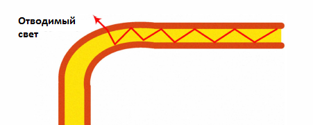
Figure 2. Macrobend
Optical fiber is inserted into the splitter, which removes part of the optical signal. This method is intrusive because it requires cutting the fiber, which will trigger the alarm. However, this type of undetected connection can work for years.
This method is used to intercept the signal from the source fiber into the fiber receiver by carefully polishing the shells to the surface of the core and then combining them. This allows some of the signal to penetrate the second fiber. This method is difficult in the field.
A V-shaped notch is a special notch in the fiber envelope close to the core, made in such a way that the angle between the light propagating in the fiber and the projection of the V-notch is more than critical. This causes a complete internal reflection, in which part of the light will leave the main fiber through the envelope and V-shaped notch.
A Bragg grating is created on the fiber core, with its help a reflection of a part of the signal from the fiber is achieved. This is achieved by the superposition and interference of UV rays produced by a laser with UV excitation.
For an accurate estimate of the bending loss of a SMF-28 type optical fiber, Maxwell’s full-vector frequency solver is used, based on the high-order finite element method and allowing adaptation of the boundary conditions — a stretching perfectly matched layer. The vector calculations of propagation constants and mode electric fields in curved waveguides are obtained. Bending losses are calculated based on the imaginary part of the propagation constant of the fundamental mode. Total losses are obtained by adding the losses of the orthogonal and base modes. The results obtained by this method are fairly accurate and were verified in [5].
For SMF-28 fiber, the core radius and refractive index are respectively.
r c = 4.15 μm and n c = 1.4493
In the shell, they are respectively equal:
r cl = 62.25 μm and n cl = 1.444.
The refractive index of air is 1.
The bending radius ρ is taken along the x axis, the mode is polarized along the y axis, and propagation occurs along the z axis, as shown in Figure 3.
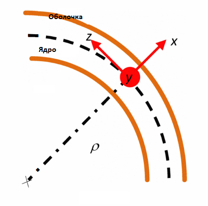
Figure 3
Figure 4 represents the bend loss in numbers as a function of the bend radius of a meter long fiber. There is a logarithmic dependence of the loss relative to the bend radius. For small bending radii (ρ <10 mm), the losses exceed 40 dB / m. With conventional bending radii (ρ> 15 mm), the loss is less than 1 dB / m

Figure 4. Numerical evaluation of bending loss as a function of bend radius
The complete listening operation can be implemented using the following steps:
The experiment included the transfer of a digital video signal via optical Ethernet from one computer to another. The connected fiber was cut up to the cladding and placed in an optical coupler (coupler), where the fiber is bent, causing the emission of a certain amount of light that violates the principle of total internal reflection. This device sends captured light to a unidirectional Ethernet converter. Further, Ethernet frames are processed and the video stream on the third PC is reconstructed. VLC player was used for streaming and playback. The protocol analyzer WireShark was used to capture packets, and the Chaosreader software was used to reconstruct video from captured packets.
The software and hardware are connected as in Figure 5. The split fiber passes from the video source to the receiver, through the coupling clamp. A part of the world is relegated to the clip and goes into a unidirectional media converter that reads Ethernet frames, which are then transmitted to the third PC, on which WireShark stands. The protocol analyzer converts Ethernet frames and extracts such information as MAC source and receiver addresses. It also processes the contents of frames and extracts IP packets from it. Information obtained from the packets includes IP addresses, signaling protocol messages, and overhead bits.

Figure 5. Experimental scheme for connection to the fiber by the method of bending
Packets collected in this way are saved in the pcap file format (packet capture). The file is then processed by the Chaosreader software, which reconstructs the original files and creates an index of the reconstructed files. To detect our captured video, we look in the directory and look for large. * .DAT files. This file is then opened in the VLC player and shows the intercepted part of the video stream.
In addition to playing video, the experimental system described here can be used to perform a number of tasks to intercept information, such as information for attacking IP addresses, stealing passwords, listening to VoIP conversations, reconstructing e-mail using free, commercial or homemade software.
The experiment described here was performed using Ethernet components, due to their greatest availability. However, some scenarios possible in real life may well look like this:
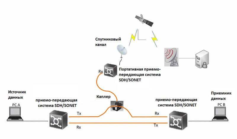
Figure 6 Connection scenario with remote processing.
Valuable information can be obtained from data networks such as SDH and SONET, the two main standards for transmitting data via fiber via backbone links and metro networks.
Information from high-speed networks is quite difficult to store and process, but high-tech analyzers of SDH protocols are available on the market, which can be used to obtain low-level source signals [6]. This partly simplifies the possible difficulties associated with data transfer speeds. Such devices can be subsequently refined to receive various types of traffic passing through the network. For example, it is possible to extract an ethernet stream that is associated with some stream of a VC4 container.
There are two important incentives for remote processing:
When using the imagination, you can easily complete all the necessary scenarios for working with remote data. For example:
1) Use of wireless internet. When using Wi-Fi, the listening computer may be located in another room or van, outside the building where the connection is made. The expert can work in relative security with the ability to access all resources.
2) Use of micro-frequency or satellite channel. Our experimental scheme was modified and Ethernet traffic was redirected to the directional satellite channel (Fig. 6).
3) Inserting a signal. With the help of the scattering method described earlier, it is theoretically possible to create a device that has the ability to transmit a signal into the fiber through modified optical coupling technology
Technologies can be developed for placing noises on the fiber without breaking the connection or even introducing malicious information.
There are three main categories of methods for preventing or minimizing the effects of unauthorized connections:
Production of fiber with additional fibers, through which a special monitoring signal is transmitted. Using this method will increase the cost of the cable, but any attempt to bend the cable causes a loss of the monitoring signal, and triggers an alarm [7].
Another method is to integrate the electrical conductors into the cable, and if the cable jacket is broken, the capacitance between the electrical conductors changes and this can be used to trigger an alarm.
This method is applicable to multi-mode fiber, in which attenuation is a function of the mode in which light propagates. Connections affect certain modes, but also affect other modes. This leads to a redistribution of energy from conducting to non-conducting modes, which changes the ratio of the energy in the fiber core and its cladding. The change in energy in the modes can be detected on the receiving side by a corresponding measurement, which will be information for making a decision whether there is a connection to the cable or not [8].
The fiber can monitor the level of optically significant power. If it differs from the set value, an alarm is triggered. However, this requires an appropriate signal coding, so that the fiber contains a constant signal level, independent of the presence of transmitted information [8].
Since the connection to the fiber takes a part of the optical signal, optical reflectometers can be used to detect connections. With their help, you can set the distance along the track where a signal level drop is detected (Fig. 7) [8]

Figure 7. Search for a connection on the optical path using an optical reflectometer
Pilot tones pass along the fiber as well as communication data. They are used to detect transmission interruptions. Pilot tones can be used to detect attacks related to jamming, but if the carrier frequencies of the pilot tones are not affected, this method is not effective in detecting such attacks. The presence of a connection can be judged only by a significant degradation of the level of the pilot tone signal [8]
These types of fibers, commonly referred to as low-loss fibers with strong bending radii, protect the data network by limiting the high losses that occur when piercing the fiber or bending it. In addition, factors such as stretching, twisting and other physical manipulations with fiber become less damaging to the light flux. There are also other types of fiber based on other production technologies [9].
Although encryption does not interfere with the connection to the fiber, it makes the stolen information of little use for intruders. Encryption is usually classified by levels 2 and 3.
An example of third-level encryption is IPSec. It is implemented on the user's side, so this causes certain delays in processing. The protocol is raised at the beginning of the session and the overall implementation can be quite complex if a large number of network elements are involved. Consider, for example, the development of multimedia subsystems. During initial development, communication between different nodes and elements is unprotected. Much later, IPSec was built into the original design, since the lower level technologies did not offer any encryption at all.
Second level encryption frees third level elements from any burden of information encryption. One of the possible sources of second-level encryption is optical CDMA, which is considered relatively secure [10-12]. This assumption is mainly based on brute force decoding methods and overlooks more advanced methods. The probability of successful interception of data is a function of several parameters, including the signal-to-noise ratio, and the fractioning of the available system capacity. [12] states that increasing the complexity of the code can increase the signal-to-noise ratio required for an attacker to “break” the coding by only a few dB, while processing less than 100 bits from the attacker can reduce the signal-to-noise ratio by 12 dB. Jumping over wavelengths and signal distribution over time in particular, and the use of O-CDMA in general, provide an adequate level of secrecy, but it highly depends on the system design and implementation parameters.
The authors thank the Prince Sultan Research Institute for Advanced Technologies for providing its resources and performing the experimental part of the work.
Connecting to optical fiber is a very tangible threat to the interests of national security, financial organizations and personal privacy and freedoms. Once connected, the received information can be used in many ways, depending on the motivation of the attacker and his technical capabilities. In this paper, we provided the concept both in the form of a simulation and in the form of a physical experiment using the connection by means of the 'connection by the bending method' and also demonstrated the possibility of the existence of different scenarios that can be performed using the available technologies. In addition to receiving information from the fiber, there are a number of techniques that allow you to insert information into it, as in the case of separation on non-uniform waves and to achieve jamming or injection of incorrect information. The apparent ease of listening to optical fiber requires certain precautions, which are also described in this article.
Stealth Fiber Connection: Methods and Precautions
M. Zafar Iqbal, Habib Fathallah, Nezih Belhaj
MZ IQBAL, H FATHALLAH, N BELHADJ. 2011. Optical Fiber Tapping: Methods and Precautions. High Capacity Optical Networks and Enabling Technologies (HONET).
')
annotation
Communication with the use of fiber is not nearly as secure as it is commonly believed. There are a number of known methods used to extract or insert information into an optical channel and avoid connection detection. Previously reported several incidents in which a successful connection was difficult to detect. This paper discusses a number of well-known methods of connecting to optical fiber, provides a report on the simulation of the optical characteristics of a fiber, to which the connection is made by the bending method, and also a proof of concept in the form of a physical experiment. There are also diagrams of various scenarios where an attacker who possesses the necessary resources and uses existing technologies may compromise the security of an optical communication channel. Discusses ways to prevent connection to the fiber, or minimize the consequences of information leakage transmitted over the communication channel.
This article is based on work supported by the Royal Air Force of the Kingdom of Saudi Arabia.
M. Zafar Iqbal works at the Prince Sultan Research Institute of Advanced Technologies (ziqbal@ksu.edu.sa)
Habib Fathalla - Associate Professor (Assistant Professor) of King Saud University (hfathallah@ksu.edi.sa)
Nezih Belhadj - Postdoc Researcher of Laval University (nbelhadj@gel.ulaval.ca)
I. INTRODUCTION
In contrast to the general concept, fiber optics are essentially not protected against third-party connections and listening. Currently, an enormous amount of critical and sensitive information is transmitted via optical communication channels, and there is a risk that it may fall into the hands of certain individuals who have the necessary resources and equipment.
Fiber tapping is a process in which the security of an optical channel is compromised by inserting or extracting light information. Fiber connection may be intrusive or non-intrusive. The first method requires cutting the fiber and connecting it to an intermediate device for retrieving information, while using the second method, the connection is performed without disrupting the data flow and interrupting the service. This article will be devoted to non-intrusive technologies.
Currently, only a few reported cases of connection to optical fiber are reported. This is associated with great difficulty in locating the connection, while the connection itself is quite simple. Here is a list of major incidents:
- 2000 A connection to the three main lines of the Deutsche Telekom company was discovered at Frankfurt Airport, Germany [1].
- 2003, a listening device was detected on a Verizone optical network [1].
- 2005, the USS Jimmy Carter submarine was upgraded in a special way to install unauthorized connections to the underwater cables [2], [3] ( A separate post on the Habré is the USS Jimmy Carter submarine, its special tasks and underwater optical cables ).
In the following sections, we will present a brief overview of unauthorized connection methods [4]. Then we will present a numerical representation of the signal loss during fiber bending, followed by a report on the physical demonstration of a prototype fiber optic device developed in our laboratory. Here we will explain the device prototype used in this equipment and software. We will also discuss possible scenarios of connection in real conditions and discuss what resources are needed to achieve these goals. As a result, we will offer several techniques for protecting optical channels against connections.
Ii. METHODS OF CONNECTING TO THE FIBER
A. fiber bending
With this connection method, the cable is disassembled to the fiber. This method is based on the principle of the propagation of light through a fiber through total internal reflection. To achieve this method, the angle of incidence of light at the transition between the fiber core itself and its cladding must be greater than the critical angle of total internal reflection .
Otherwise, part of the light will be emitted through the shell of the nucleus. The value of the critical angle is a function of the reflection parameters of the core and its shell and is represented by the following expression:
θ c = cos -1 (μ cladding / μ core ), with μ cladding <μ core ;
Here, θ c is the critical angle, μ cladding is the shell refractive index, μ core is the core refractive index
When the fiber is bent, it is bent in such a way that the angle of reflection becomes less than critical, and light begins to penetrate the envelope.
Obviously, there may be two types of folds:
1) Microbend
The application of external force leads to a sharp, but at the same time microscopic curvature of the surface, resulting in axial displacements of a few microns and a spatial displacement of the wavelength of a few millimeters (Fig. 1). Light penetrates through the defect and it can be used to retrieve information.
Figure 1. Microbend
2) Macro bend
For each type of fiber, there is a minimum permissible bending radius. This property can also be used to retrieve information. If the fiber is bent at a smaller radius, then light transmission is possible (Fig. 2), sufficient for retrieving information. Usually the minimum bend radius of single-mode fiber is 6.5-7.5 cm, with the exception of a special type of fiber. Multimode fiber can be curved up to 3.8 cm.
Figure 2. Macrobend
B. Optical splitting
Optical fiber is inserted into the splitter, which removes part of the optical signal. This method is intrusive because it requires cutting the fiber, which will trigger the alarm. However, this type of undetected connection can work for years.
C. Use of Heterogeneous Waves (Evanescent Coupling)
This method is used to intercept the signal from the source fiber into the fiber receiver by carefully polishing the shells to the surface of the core and then combining them. This allows some of the signal to penetrate the second fiber. This method is difficult in the field.
D. V-neck (V Groove Cut)
A V-shaped notch is a special notch in the fiber envelope close to the core, made in such a way that the angle between the light propagating in the fiber and the projection of the V-notch is more than critical. This causes a complete internal reflection, in which part of the light will leave the main fiber through the envelope and V-shaped notch.
E. Scattering
A Bragg grating is created on the fiber core, with its help a reflection of a part of the signal from the fiber is achieved. This is achieved by the superposition and interference of UV rays produced by a laser with UV excitation.
Iii. MODELING
A. Methodology
For an accurate estimate of the bending loss of a SMF-28 type optical fiber, Maxwell’s full-vector frequency solver is used, based on the high-order finite element method and allowing adaptation of the boundary conditions — a stretching perfectly matched layer. The vector calculations of propagation constants and mode electric fields in curved waveguides are obtained. Bending losses are calculated based on the imaginary part of the propagation constant of the fundamental mode. Total losses are obtained by adding the losses of the orthogonal and base modes. The results obtained by this method are fairly accurate and were verified in [5].
B. Data for modeling.
For SMF-28 fiber, the core radius and refractive index are respectively.
r c = 4.15 μm and n c = 1.4493
In the shell, they are respectively equal:
r cl = 62.25 μm and n cl = 1.444.
The refractive index of air is 1.
C. Calculation of power loss.
The bending radius ρ is taken along the x axis, the mode is polarized along the y axis, and propagation occurs along the z axis, as shown in Figure 3.
Figure 3
Figure 4 represents the bend loss in numbers as a function of the bend radius of a meter long fiber. There is a logarithmic dependence of the loss relative to the bend radius. For small bending radii (ρ <10 mm), the losses exceed 40 dB / m. With conventional bending radii (ρ> 15 mm), the loss is less than 1 dB / m
Figure 4. Numerical evaluation of bending loss as a function of bend radius
Iv. EXPERIMENT ON CONNECTING TO THE FIBER
A. Sequence of actions when connecting to optical fiber.
The complete listening operation can be implemented using the following steps:
- Receive optical signal from fiber
- Signal detection
- Transmission mechanism discovery (protocol decoding)
- Software processing for detecting frames / packets and extracting necessary data from them.
The experiment included the transfer of a digital video signal via optical Ethernet from one computer to another. The connected fiber was cut up to the cladding and placed in an optical coupler (coupler), where the fiber is bent, causing the emission of a certain amount of light that violates the principle of total internal reflection. This device sends captured light to a unidirectional Ethernet converter. Further, Ethernet frames are processed and the video stream on the third PC is reconstructed. VLC player was used for streaming and playback. The protocol analyzer WireShark was used to capture packets, and the Chaosreader software was used to reconstruct video from captured packets.
B. Procedure
The software and hardware are connected as in Figure 5. The split fiber passes from the video source to the receiver, through the coupling clamp. A part of the world is relegated to the clip and goes into a unidirectional media converter that reads Ethernet frames, which are then transmitted to the third PC, on which WireShark stands. The protocol analyzer converts Ethernet frames and extracts such information as MAC source and receiver addresses. It also processes the contents of frames and extracts IP packets from it. Information obtained from the packets includes IP addresses, signaling protocol messages, and overhead bits.
Figure 5. Experimental scheme for connection to the fiber by the method of bending
Packets collected in this way are saved in the pcap file format (packet capture). The file is then processed by the Chaosreader software, which reconstructs the original files and creates an index of the reconstructed files. To detect our captured video, we look in the directory and look for large. * .DAT files. This file is then opened in the VLC player and shows the intercepted part of the video stream.
C. Possible actions during wiretapping
In addition to playing video, the experimental system described here can be used to perform a number of tasks to intercept information, such as information for attacking IP addresses, stealing passwords, listening to VoIP conversations, reconstructing e-mail using free, commercial or homemade software.
V. FURTHER CONNECTION SCENARIOS.
The experiment described here was performed using Ethernet components, due to their greatest availability. However, some scenarios possible in real life may well look like this:
Figure 6 Connection scenario with remote processing.
A.Connecting to the data network
.Valuable information can be obtained from data networks such as SDH and SONET, the two main standards for transmitting data via fiber via backbone links and metro networks.
Information from high-speed networks is quite difficult to store and process, but high-tech analyzers of SDH protocols are available on the market, which can be used to obtain low-level source signals [6]. This partly simplifies the possible difficulties associated with data transfer speeds. Such devices can be subsequently refined to receive various types of traffic passing through the network. For example, it is possible to extract an ethernet stream that is associated with some stream of a VC4 container.
Connection with remote processing
There are two important incentives for remote processing:
- When connecting to the far high-speed (several Gbit / s) communication channels, the role of storage becomes extremely important. Captured packets fill the disk extremely quickly.
- Attracting network experts to work in the field can be very costly. It is more convenient to organize their work in a remote processing center where there is any necessary equipment that is difficult to carry out in the field.
When using the imagination, you can easily complete all the necessary scenarios for working with remote data. For example:
1) Use of wireless internet. When using Wi-Fi, the listening computer may be located in another room or van, outside the building where the connection is made. The expert can work in relative security with the ability to access all resources.
2) Use of micro-frequency or satellite channel. Our experimental scheme was modified and Ethernet traffic was redirected to the directional satellite channel (Fig. 6).
3) Inserting a signal. With the help of the scattering method described earlier, it is theoretically possible to create a device that has the ability to transmit a signal into the fiber through modified optical coupling technology
Technologies can be developed for placing noises on the fiber without breaking the connection or even introducing malicious information.
Vi. PROTECTION AGAINST CONNECTIONS.
There are three main categories of methods for preventing or minimizing the effects of unauthorized connections:
A. Cable monitoring and monitoring.
1. Monitoring signals near the fiber.
Production of fiber with additional fibers, through which a special monitoring signal is transmitted. Using this method will increase the cost of the cable, but any attempt to bend the cable causes a loss of the monitoring signal, and triggers an alarm [7].
2) Electrical conductors
Another method is to integrate the electrical conductors into the cable, and if the cable jacket is broken, the capacitance between the electrical conductors changes and this can be used to trigger an alarm.
3) Power monitoring mod.
This method is applicable to multi-mode fiber, in which attenuation is a function of the mode in which light propagates. Connections affect certain modes, but also affect other modes. This leads to a redistribution of energy from conducting to non-conducting modes, which changes the ratio of the energy in the fiber core and its cladding. The change in energy in the modes can be detected on the receiving side by a corresponding measurement, which will be information for making a decision whether there is a connection to the cable or not [8].
4) Measurement of optically significant power
The fiber can monitor the level of optically significant power. If it differs from the set value, an alarm is triggered. However, this requires an appropriate signal coding, so that the fiber contains a constant signal level, independent of the presence of transmitted information [8].
5) Optical reflectometers
Since the connection to the fiber takes a part of the optical signal, optical reflectometers can be used to detect connections. With their help, you can set the distance along the track where a signal level drop is detected (Fig. 7) [8]
Figure 7. Search for a connection on the optical path using an optical reflectometer
6) Methods using pilot tone:
Pilot tones pass along the fiber as well as communication data. They are used to detect transmission interruptions. Pilot tones can be used to detect attacks related to jamming, but if the carrier frequencies of the pilot tones are not affected, this method is not effective in detecting such attacks. The presence of a connection can be judged only by a significant degradation of the level of the pilot tone signal [8]
B. Strong fiber.
These types of fibers, commonly referred to as low-loss fibers with strong bending radii, protect the data network by limiting the high losses that occur when piercing the fiber or bending it. In addition, factors such as stretching, twisting and other physical manipulations with fiber become less damaging to the light flux. There are also other types of fiber based on other production technologies [9].
C. Encryption
Although encryption does not interfere with the connection to the fiber, it makes the stolen information of little use for intruders. Encryption is usually classified by levels 2 and 3.
1) Level 3 encryption
An example of third-level encryption is IPSec. It is implemented on the user's side, so this causes certain delays in processing. The protocol is raised at the beginning of the session and the overall implementation can be quite complex if a large number of network elements are involved. Consider, for example, the development of multimedia subsystems. During initial development, communication between different nodes and elements is unprotected. Much later, IPSec was built into the original design, since the lower level technologies did not offer any encryption at all.
2) Second level encryption.
Second level encryption frees third level elements from any burden of information encryption. One of the possible sources of second-level encryption is optical CDMA, which is considered relatively secure [10-12]. This assumption is mainly based on brute force decoding methods and overlooks more advanced methods. The probability of successful interception of data is a function of several parameters, including the signal-to-noise ratio, and the fractioning of the available system capacity. [12] states that increasing the complexity of the code can increase the signal-to-noise ratio required for an attacker to “break” the coding by only a few dB, while processing less than 100 bits from the attacker can reduce the signal-to-noise ratio by 12 dB. Jumping over wavelengths and signal distribution over time in particular, and the use of O-CDMA in general, provide an adequate level of secrecy, but it highly depends on the system design and implementation parameters.
ACKNOWLEDGMENTS
The authors thank the Prince Sultan Research Institute for Advanced Technologies for providing its resources and performing the experimental part of the work.
VII. CONCLUSION
Connecting to optical fiber is a very tangible threat to the interests of national security, financial organizations and personal privacy and freedoms. Once connected, the received information can be used in many ways, depending on the motivation of the attacker and his technical capabilities. In this paper, we provided the concept both in the form of a simulation and in the form of a physical experiment using the connection by means of the 'connection by the bending method' and also demonstrated the possibility of the existence of different scenarios that can be performed using the available technologies. In addition to receiving information from the fiber, there are a number of techniques that allow you to insert information into it, as in the case of separation on non-uniform waves and to achieve jamming or injection of incorrect information. The apparent ease of listening to optical fiber requires certain precautions, which are also described in this article.
LINKS
- Sandra Kay Miller, Hacking at the Speed of Light, Security Solutions Magazine, April 2006
- Davis, USN, RADM John P. “USS Jimmy Carter (SSN-23): Expanding Future SSN Missions”. Undersea Waifare, Fall 1999 Vol.2, No. I
- Optical Illusion by Sandra Kay Miller Information Security Issue: Nov 2006.
- Keith Shaneman & Dr. Optical Network Security Stuart Gray, IEEE Military Communications Conference 2004.
- R. Jedidi and R. Pierre, High-Order Finite-Element Methods for Optical Waveguides, LLT, Vol. 25, No. 9, pp. 2618-30, SEP 2007.
- FTB-8140 Transport Blazer - 40143 Gigabit SONETISDH Test Module, EXFO
- "Optical Fiber Design for Secure Tap Proof Transmission", US Patent No. 6801700 B2, Oct. 5,2004.
- All Optical Networks (A ON), National Communication System, NCS TIB 00-7, August 2000
- DrakaElite, BendBright-Elite Fiber for Patch Cord, Draka Communications, July, 2010
- W. Ford, Computer Communications Security, Upper Saddle River, NJ: Prentice-Hall, 1994.
- DR Stinson, "Cryptography", Boca Raton, FL: CRC, 1995.
- N. Ferguson and 8. Schneier, "Practical Cryptography", Indianapolis, IN: Wiley, 2003.
Source: https://habr.com/ru/post/176677/
All Articles