Do-it-yourself laser show. Part 1
Drawing beam: past, present and future.
This is an introductory article on the history of development and principles of operation of vector information display technologies.
Do not be offended by the fact that everything is too "wikipedichno" here, I just got tired of stupid questions.
Those who are in the subject, may find it interesting to read the end of the article and can safely go to the second part of the link at the end.
A bit of history ...
It all started with the fact that a certain German Ferdinand Brown tried to put into practice the so-called cathode rays - a beam of electrons accelerated in an electric field, and invented the very first cathode ray tube (CRT, CRT) in 1897. It was a tube with a cold cathode, an electromagnetic deflecting system along one of the axes (on the second axis it was a rotating mirror) and a screen coated with phosphor. In the course of further improvements by other scientists (Boris Rosing, John B. Johnson, Harry Weiner, and television inventor Vladimir Zvorykin), a heated cathode, a deflection system along the second axis, and a beam intensity modulator were added to control the brightness of the point on the screen. Thus was born the modern cathode-ray tube.
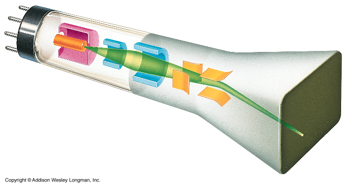
The electron beam in it changes its trajectory in the electric field of the plates of vertical and horizontal deflection (shown in yellow in the picture) and hits the screen phosphor, causing it to glow. The coordinates of the glow point in such a system are determined by the voltage on the deflecting plates. Approximately such CRTs were installed in analog oscilloscopes. In addition to electrostatic, there is a magnetic beam deflection system - the electron beam flies through the magnetic field formed by the coils and changes its trajectory depending on the current strength in the coils.
')
Using the inertia of human vision and the afterglow of the phosphor, it became possible to create drawings on the screen and a new way of displaying information that was used by engineers at the Massachusetts Institute of Technology (MIT) appeared, creating the first computer Whirlwind-I (1950) with the latest output device vector scanning display. This was the beginning of the development of displays with vector scanning (with arbitrary beam scanning).
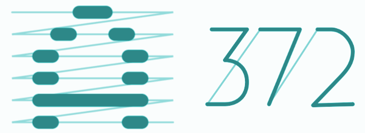
In the well-known raster method of image formation (in the figure on the left), the beam, sliding along the lines, forms an image from discrete elements — pixels forming the image; in the vector method (in the figure on the right), the beam slides, using vectors, to graphic primitives — straight, rectangle, circle, or curve — forming an image.
Since the end of the 60s of the last century, displays in vector scanning have become widespread, and even then, unlike raster displays, they could boast resolutions up to 4096x4096 pixels.
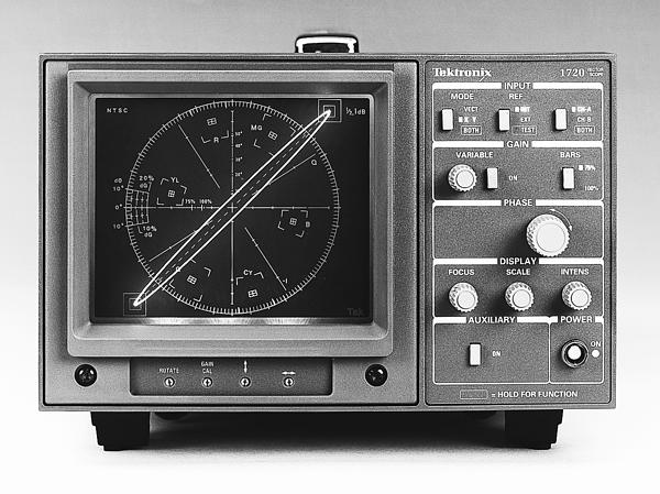
Until recently, such displays were actively used (in some places they are still used) in test equipment:
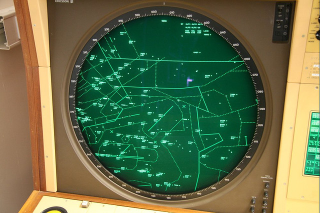
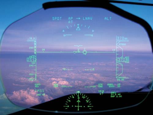
as display devices at radar stations and in air traffic control:
and, of course, in oscilloscopes:
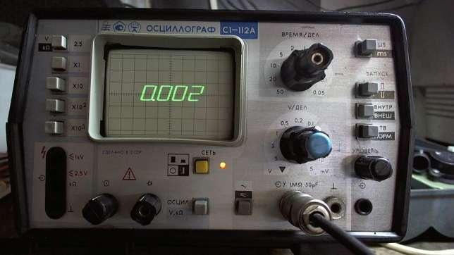
Many both old and modern oscilloscopes have the ability to work in the mode of an analog vector display. To do this, switch the oscilloscope to X / Y sweep mode and use the X input to control the horizontal position of the beam (some models also have a Z input that controls the brightness of the beam). However, on modern digital oscilloscopes without the “digital phosphorus” function, the vector image loses all its attractiveness and looks like only a simple set of points forming vectors.
The present
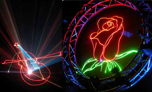
Lasers have replaced lamps, and with the reduction in the cost of memory and the development of devices with raster scanning, vector scanning is used only in certain niches (and mainly in avionics and more recently in the automotive industry - HUD-image display systems from the external environment, as well as in laser engraving and laser shows).
Since the next article will be about the laser projector - consider how he rejects the drawing beam.
Currently, two ways to control a laser beam are popular, and each has its own advantages and disadvantages:
1. Acousto-optic deflector (AOD)
- Advantages: high speed beam deflection.
- Disadvantages: low resolution, small angular scanning field (beam deflection angle), difficulty of working with high power laser beams, expensive high-frequency control system.
AOD works as follows. An acoustic wave with frequencies of tens to hundreds of megahertz is excited in an optically active crystal (for example, TeO 2 ); when a laser beam passes through such a crystal, due to diffraction or refraction phenomena, the direction of the beam changes. In a diffracted AOD, the angle of deflection of the diffracted beam is controlled by varying the frequency of the acoustic wave. In refractive AOD, the deviation occurs due to the curvature of the path of the beam when a crystal with inhomogeneous deformation passes through the medium, which occurs under the influence of a traveling acoustic wave.
2. Mechanical scanning system on galvanometers
- Advantages: the ability to work with laser beams of any power that can withstand mirrors, high resolution and positioning accuracy, a small price.
- Disadvantages: low sweep speed due to the use of mechanical parts in the system.
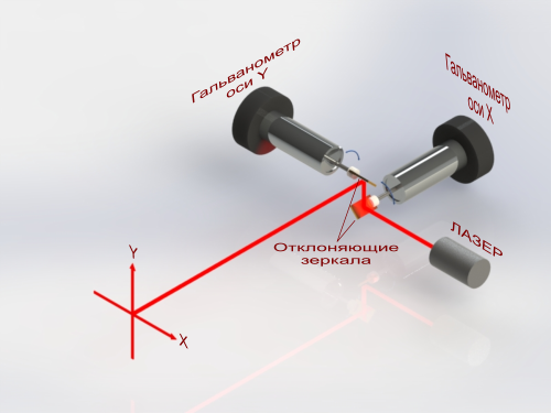
Such a system is based on galvanometers - devices consisting of an electromagnet and a permanent magnet mounted on the same axis with a mirror.
When the current in the coil changes, the permanent magnet, interacting with the coil field, turns the axis with the mirror by an angle proportional to the current passing through the coil. When combining two such galvanometers, it becomes possible to control the position of the beam on a plane, as shown in the figure below.
Future
In the summer of 2012, one interesting event happened that few people noticed.
Sumitomo Electric and Sony presented the world's first miniature direct-emitting green laser. Diodes directly emitting red and blue light have already been introduced to the pico-projector market, and only directly emitting green laser diodes have not yet been commercialized. Instead, synthetic methods were used to double the frequency of laser diodes that generate near-infrared radiation. It was the absence of directly emitting green lasers on the market that limited the visibility characteristics, price and mass (mobile and automotive) applications of laser technologies.
The invention of the green laser diode gives new impetus to the development of commercially available technologies HUD and HMD (Head mounted display), as well as mobile pico projectors.
One of the most promising solutions in the field of HUD are laser scanning MEMS technologies that can always provide a focused, high-definition virtual image of high brightness, as well as low consumption, size, weight and price of the device.

Laser scanning technology is somewhat similar to the scanning system on galvanometers and is based on using (to form a complete set of colors) combinations of three basic colors — red, green, and blue — from laser diodes of the corresponding color. The combined laser beam, falling on a microminiature mirror made according to MEMS technology, deviates by the angle set by the electronic scanning system. Due to the miniature of the mirror, the scanning speed allows such systems to work in both vector and raster modes. Scan resolution can be several times higher than current Full HD.
The world's first commercial laser scanning MEMS-block HUD, projecting information on the windshield of augmented reality through directly emitting lasers (including the new green), recently appeared in Japan. Pioneer Corporation has released the world's first automotive GPS navigation system based on MicroVision technology with augmented reality - Poineer CyberNavi .
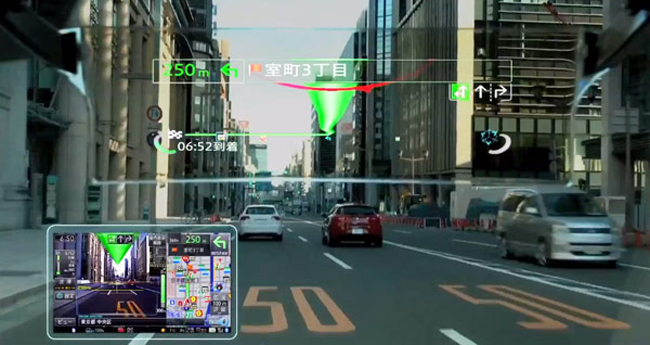
The AR-HUD system projector module is installed in the sun visor on the side of the driver's seat, the HUD display is a sheet of transparent plastic that is mounted in the driver's field of view opposite the windshield, and the 37-inch virtual display is about 3 meters from the driver's eyes. HUD virtual elements are formed by means of scanning MEMS mirrors of the projector, projecting laser beams of three basic colors of the RGB space, giving a full-color image with a high level of contrast.
Laser scanning technologies will soon be widely used in augmented reality glasses (for example, Google Glass), for displaying information on the windshield of cars, in motorcycle helmets and as mobile projectors in cell phones.
In the next part, I will tell you more about how a laser projector for light shows is arranged, and give you a ready-made high-speed DAC circuit. And as a bonus - I will tell you how to display video on an oscilloscope using three wires and a connector.
Literature
- Wiki: Cathode Ray Tube
- Wiki: Kinescope
- PDF: Acousto-optic effect
- Smallest Embedded Pico-Projector for Next-Generation Smart Phones
- Omicron starts Serial Production of Direct Diode Lasers green
- MicroVision builds on Pioneer deal
- Big encyclopedic polytechnic dictionary. 2004.
- Journal of Modern Electronics, №11, 2012, p. 144 "Green light in a roadmap of laser scanning technologies"
Source: https://habr.com/ru/post/176527/
All Articles