Light music gift favorite with your own hands

It will be a question of a device very simple to manufacture (even for a beginner electronics amateur), but at the same time extremely interesting and useful - an electronic “music box”. Also, as an example, I will show and tell you about one of the possible embodiments and applications of this device - about the last gift made to its base for its girlfriend.
History of creation
There will be a lot of letters relevant indirectly enough, and if you want, you can go directly to the description of the device.
It all started a long time ago, several years ago, when I wanted to make a girl some interesting, original and memorable birthday gift. And be sure to do it yourself. There was very little time left before the holiday, two days, during which it was necessary to invent something and, in fact, realize it. The day was spent in thought - hundreds of various options were spinning in my head, from all sorts of LED flashing lights, to various electromechanical handicrafts. But all this was not that: either it was too simple and beaten up, or vice versa, it was rather difficult (and there is no time left at all!). Suddenly a simple but wonderful, as it turned out, idea came to my mind: why not make a music card? And not simple, but with a "chip", with an original melody. Moreover, we had “our own song”, under which we met and which caused us all sorts of pleasant romantic memories and experiences.
So the very first version of the “music box” was born, the progenitor, so to speak. Very simple, quick-assembled mounted assembly from PIC12F675, piezodynamics, photodiode, a pair of resistors, a three-volt element 2016 and packed into a postcard drawn in photoshop. This postcard, as a result, was able, when it opened (and when light hit the photodiode), to register that melody with a rectangle. This is so simple and simple.
But the idea turned out to be very successful, many times more than I expected. Later, I made several more such simple postcards at the request of my friends, for their second half. And in each case, such a gift caused a lot of emotions from both the donee themselves and their parents, friends and acquaintances :)
It took a lot of time, everything started spinning, the project was forgotten. But it so happened that I remembered the music box again. This time it was supposed to be a gift on March 8th. At that time, I was actively studying Atmel microcontrollers, in particular, I was playing with ATtiny45, and decided to improve the music module for this. Moreover, this time there was a lot. Then it all started.
Searching for different information on the Internet, I came across the website of Mr. Chan, well-known in narrow circles. And more specifically, to one of its designs, a miniature synthesizer , just on the beloved MK :) Some time ago, I almost finished the four-channel synthesizer on the PIC18, but, alas, I have destroyed the groundwork in hearts (which I regretted more than once). And Chan’s construction was completely self-sufficient and complete. It remained to add to it only the "trigger" and go!
I finished the code a bit and the trigger was ready. But then everything turned out to be a little less rosy. The main problem of the design was that it sounded too quiet. No matter how hard I tried, with the direct drive, the dynamics of the MK pins turned out to be quiet and that's it! As a result, a volition was made to add a power amplifier. The choice fell on the LM4900 then present in Terraelectronics. Again, we had to make some more changes to Mr. Chan’s code so that the synthesizer worked correctly with an external amplifier — to make power-saving foot control, so that the amp wouldn't eat the battery when idle and reconfigure the PWM to output the signal from one pin correctly. After these changes, the prototype earned just perfect. Then I drew the first version of the board (in which, as it turned out, the jamb crept in :) and assembled the music box humanly. Further, all along the beaten track is a homemade postcard, installation of the module and donation-presentation.
Of course, this device was several heads taller than the previous ones - the very realistic sound of the “real” box and polyphony made themselves felt :) The gift, like last time, a long time ago, caused a stir. And I also gathered about a dozen of such modules to my friends.
Now about the device itself
The current version of the module, the third in a row, contains several more changes and one interesting innovation - a light - music channel to which you can connect, for example, an LED. But first things first.
')
Let's start with the scheme, it is very simple:
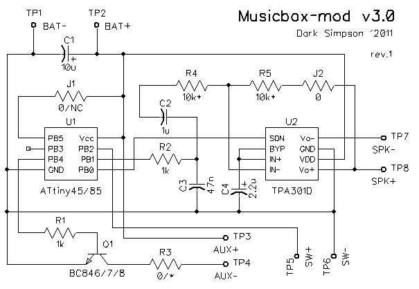
Her heart is an ATtiny45 / 85 microcontroller. He is engaged, in fact, in the synthesis of music, manages the light-music channel and the power saving of the amplifier. The second most important element is the TPA301D audio power amplifier. A speaker is connected to the amplifier, which is located outside the module. There is also a BC847 transistor that controls the light-music channel and several passive elements - resistors and capacitors . It all feeds from 2-3 alkaline cells (for example, AAA), located in an external battery pack (the most common, Chinese). As you can see, the scheme is really elementary.
The principle of the scheme
Most of the time the device is in "sleep mode". The MK falls asleep at the command of the firmware immediately after switching on, previously “putting it to sleep” and the amplifier, setting a “SHUTDOWN” high level on its leg (by connecting the weak “PB0” leg tightening to the “+” power inside the MK). MK wakes up by interrupting c PB2 / INT0 . Initially, the leg is also tightened to the “+” power inside the MK and it must be closed to the ground.
From the “PB1 / OC1A” foot, the MK sound PWM signal, in order to filter it from the carrier, passes through the simplest RC filter of the second order ( R2-C3 ), which must be calculated (and in our case it can be just “estimated”) cut-off frequency, much smaller (ten times) of the carrier frequency. And the filtered signal, through the blocking capacitor C2 , is already fed to the input of the amplifier.
The MC controls the additional light-music channel. For this purpose, the npn transistor Q1 is used in the key mode, the base of which is connected to the foot of the MK “PB4 / OC1B” via the current limiting resistor R1 . A limiting resistor ( R3 ) can also stand in the collector circuit - it will not be superfluous. The transistor is also controlled by a PWM signal. Everything is done very simply - in the best traditions of “flashing” LEDs from the “Arduin” :)
On nutrition there is an interchange tantalum ( C1 ), the simplest body kit of the amplifier, performing both the role of decoupling ( C4 ) and adjusting the gain (volume) coefficient, in general, is peeped at the datasheet on the amplifier. If necessary, KU can be quite accurately calculated by the most common for the OS method of the ratio of the resistances of the input resistor R4 and feedback resistor R5 , since the volume can be useful to correct for a particular speaker or design.
Printed circuit board
Simple to ugliness, drawn in DipTrace:
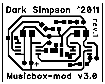
This is the third version, which takes into account all previous shortcomings.
The board is designed for surface mounting and one-sided, which greatly simplifies the process of home-made. You can use any method: laser-ironing, photo-ability or even draw tracks with a marker (for an amateur, of course).
All elements are 0805 (including “zero” jumpers), tantalum - A or B, transistor in SOT23 and MK with amplifier in SO-8. All "peripheral" components - the battery pack, the speaker, the LEDs and the button (photoresistor, reed switch) are fed to the corresponding "circles" on the board. That's all.
Software part
A little bit about sound synthesis
About the method of synthesis used in the device, you can lucidly read the original in Mr. Chan 's here . You can even google "wavetable synthesis". If you do not speak the language, then briefly, a sound sample is stored in the memory of the MC (separately taken sound), the so-called. “Wavetable” , which in our simplest case is conventionally divided into two logical parts, which generally form the “envelope” - “attack” , the beginning of each new sound, and “sustain” , an excerpt, a fragment that constantly loops through the sound of the note. There is also a “decay” , “voice” part, which sounds after removing the note. We have implemented it simply by gradually damping the sound of “sustain”. The MC has a timer that causes an interruption with a certain frequency, where, according to the current position of the “envelope” and the pitch of the note, the desired value is selected from the sample memory. Moreover, in this way, you can simultaneously synthesize several channels (that is, notes) at the same time, everything depends only on the computing power of the MC and the sampling frequency (sound quality). Then these values are mixed and sent “to the exit” (in our case - to the PWM control register). All this disgrace, as I mentioned above, is called "Wavetable synthesis" or "tabular wave synthesis."
The core of Mr. Chan’s synthesis has remained virtually unchanged. Only the PWM output method has changed a bit, due to the rejection of the “direct drive” dynamics from the MK. He added the “trigger mechanism”, the power management of the MK and the amplifier, and also wrote the code for controlling the light and music channel, which works like this: by a special event from the score, the LED lights up in the right places, and then it turns off smoothly. Well, "ported" (much, of course, said) code in the Studio, for convenience.
The code is written in AVR assembly and consists of several files: “mbox.asm” is the program itself; “Notes_pitch.inc” - an indication of the correspondences of the mnemonic names of notes used in the score to the coefficients of the increment of the position of the pointer in the sample (that is, as a result, the pitch); “Wavetable.inc” - sample data (“table”) and decay decay curve; and “score.inc” , as you may have guessed from the title, contains the score of the work being performed, the “notes”.
Initially, in “wavetable.inc”, Chan himself “crammed” the sound of the box. But if necessary and desired, it can be changed to any other, using the auxiliary script "wav2asm.pl" , or simply by hand.
The situation was more complicated with the score. Initially it was supposed to write them by hand, which undoubtedly will bring a lot of pleasure to masochistic people, especially if the score is not at all simple.
For a person who is going to use his score and, presumably, on this occasion, at least somewhat familiar with music and musical notation, it would be easier to draw the score in any available music editor and use it in some way. For this, I wrote a special converter program that accepts a MIDI file of format 0 “at the input”, and “output” gives the finished file “score.inc”. She can independently arrange the LED ignition events for all notes in the first channel, that is, if the melody is initially logically separated from the accompaniment and put into the first channel of the midi file, we will get a score that will light the LED in time with the melody if want and put daw. In fact, this is probably one of the most beautiful ways for an additional channel to work.
Another program can transpose the resulting score up to one or two octaves up / down, which in certain cases can greatly facilitate the work of writing a score.
The program interface looks simple, clear and simple, and the source code for Delphi is included in the package:
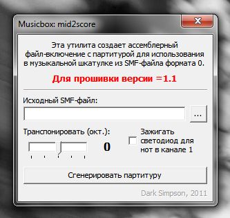
By the way, as I was told at one time (for some reason I didn’t think about it at all), there are a lot of resources on the Internet, from where you can get ready-made midish with desired melodies. They will need only a little refinement for use in my converter. And some may not even have to refine.
What else might be needed?
Suppose you bought / got all the necessary components, in one way or another made a board, or, alternatively, you just soldered all the hinged wiring. What else is needed? It will take a programmer. If you already have or are dealing with AVR, then you most likely already have it. And so, for example, “USBasp” in hundreds of incarnations or whatever . There is nothing supernatural. In the archive with everything, there is an already compiled binary, which can be immediately poured into the controller and used if there is no intention to edit and reassemble something.
Application
And now, as promised, I will tell and show one of the hundreds of possible applications of the module, the musical rose of Kawasaki.
Rosa Kawasaki , one of the masterpieces of origami, is generally a separate large topic, which you can fully familiarize yourself with on the Internet.
Constructively, the thing itself is made of two parts:
The first, a rose , is folded from a colored sheet of paper and glued onto a twisted stem with leaves (also folded from colored paper). A thick copper wire passes through the stem (for strength) and a small neodymium magnet is hidden at the bottom.
The second part, a vase , is cut and glued from thick white cardboard. Inside it, the module itself is installed, a speaker (glued to a resonating volume filled with cotton), super-bright white wide-angle LEDs matted with a fine sandpaper and a battery pack mounted on the bottom of the vase for easy access to the batteries. And, of course, the reed switch is a “trigger mechanism”, which is paired with a magnet in the stem. It is installed in such a way that the module is activated when removing the rose from the vase.
Schematically, it looks like this:

But a couple of photos of the prototype:


And video work. The composition “Tenderness” plays on the video, which I transferred to the box, and which is included in the archive as a source (I typed in Sibelius) and a midish, as well as a ready-made score:
As usual, my eternal problem with a normal sound in video makes itself felt. A thousand apologies. If it is interesting to listen in normal quality as the construction sounds, then you can download the empathish from here .
This is just one of the possible uses of the structure. How you use your module will depend on your imagination;)
I can only wish you success in this difficult creative work.
Give joy to your loved ones and loved ones!
Download the archive with source codes and binary firmware, programs, drawing schemes and boards, score and other materials here.
Disclaimer and thanks :)
PS This is my first post here, so please don’t kick much if in some way or somehow I was wrong.
PPS I have already published this material partially and in a scattered form in my LiveJournal, more for myself, to notice some moments and leave a memo, but since the device turned out to be very interesting and successful, and already several modifications of this device in almost a couple of dozens of incarnations they fulfilled (and continue to fulfill) their destiny with interest - they please the ears and eyes of the girls - I decided to tell you about him and to you.
PPPS Also, the story of the following device here, on Habré, was long ago comrade dlinyj pushed me , and then, finally, I gathered my strength, knocked off the material and decided to write the same post, for which Long thank you so much!
Source: https://habr.com/ru/post/176403/
All Articles