Wiren Board - embedded computer with Wi-Fi, GPRS, GPS, NFC and Ethernet out of the box
update: We are still alive and finally opened sales!
The new version has become much better and now looks like this:

Details in our blog .
/ update
')
TL; DR (Abstract)
We made a small “single-board” embedded computer with a good set of peripherals, mostly wireless (GSM / GPRS, NFC, Wi-Fi, GPS, Ethernet, etc). The working title is Wiren Board (from Wir eless En abled)
It is assumed that it will be used for all kinds of automation - that is, as a “brain” for equipment. If you want to make a smart device without developing your own complex iron entirely, then this is for you. However, for DIY, our computer is also very useful, and we have not forgotten about this direction during development. If you need to add something specific - the functionality can be expanded with ready-made modules. What else is nice, the cost of the computer, we plan to make only about $ 100.
The first version is ready, pre-order is open.
What led us to the development of an embedded computer, which stages we went through, and what happened in the end - read on.
What for?
The story is quite banal: last fall we began to think how to make a certain device.
In the process, we figured out that writing software and connecting all peripherals to a device with Linux is incomparably easier than to a device with microcontrollers, with almost the same cost of hardware. The device we planned was massive and cheap, so we did not consider a raspberry pi with a usb hub wound with a blue electrical tape. Developing your board from scratch seemed more difficult than anything else taken together, and there was nothing ready for a reasonable price on the market.
We thought it would be great to have a fee that would satisfy our needs, cost like a raspberry pi, not as a Boeing with passengers and, most importantly, would be available for purchase in any quantity. Buy one, turn around in your hands and buy a thousand, if necessary. In such dreams, the concept of our future product was born: a board that combines a developer kit, a weight and size layout and a finished product. In short, to develop as if it were a raspberry pi, but to no electrical tape.
The board had to be flexibly configured - first of all, to reduce the price in case of mass use. On the other hand, the board in the maximum configuration should be available for immediate retail purchases and development, and should not differ significantly from the serial solution in terms of dimensions and hardware. A serial copy can be obtained by expanding the functionality of the base board with the necessary compact modules, or vice versa - by cutting back on unnecessary functionality.
The niche, it seemed, was almost free: despite the boom of arduino, and then single-board computers of all kinds, nothing like that for the industry or for more or less serious DIY applications did not appear. The situation with wireless communications of all kinds was very sad.
How?
If you want to make a device with a normal processor and Linux on board, then you have several options. You can develop an expansion card for your favorite single-board computer (r-pi), you can use a ready-made processor module, or you can develop everything from scratch.
Each of these options has its pros and cons.
Pay-expansion is the simplest solution, but the price, size and general flexibility of such a solution leave much to be desired. In addition, almost all single-board computers are focused on “desktop” applications: it is rather difficult to install, for example, raspberry pi on a quadcopter or a car. On the other hand, it is possible to make such a fee LUT at home on the knee.
The use of System on Module (for example, Carambola , Aria ) has become very popular lately. The bottom line is that you use on your board a ready-made module containing a processor (more precisely, SoC) and memory. The module can be inserted into a socket or soldered to the board. In this case, you are free from the headaches associated with the wiring of the processor and memory, and you can design a much more compact device and a cheaper device. The disadvantages of this approach stem from its merits: on your “motherboard” you now have to implement a power circuit, bring out the interface connectors, etc. In addition, you are still limited by the capabilities of a particular module. Another problem is the price of such decisions. If you can significantly reduce the cost of production of your board with an increase in production, the price of the finished SoM remains almost constant.
The last option is the development of the board from scratch. You yourself plant the processor, memory, and all the peripherals you need specifically for your board. An excellent example of this approach to development is our competitors . When developing a board, you will encounter all the delights of wiring high-frequency components, designing multi-layer boards, with difficulties in supplying chips and organizing production. The result achieved may be wonderful, but the time will not return.
We were very worried about everything written above, and we were painfully thinking what to do.
As a result, we stumbled upon a wonderful company Olimex and their equally wonderful single board computer . The use of Olinuxino Micro as SoM in our board has many advantages.
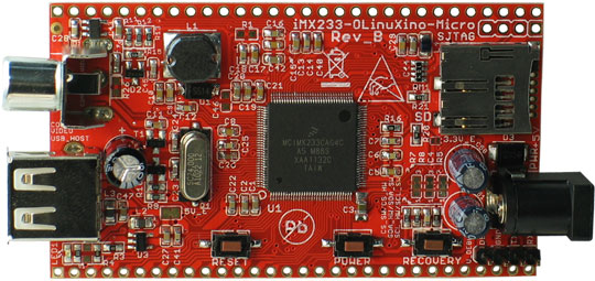
Firstly, Olinuxino Micro is not exactly SoM, but rather a full-fledged single board computer that can be easily integrated into its hardware. It already has a micro-SD card slot, a power connector, etc. At the same time, the Freescale i.mx233 processor used, although not very fresh, but fully satisfies our needs: it is industrial-grade, supported by the manufacturer, will be produced until 2017, all documentation is open to it, it is fully supported by the Linux kernel, without any problems You can buy it, and it costs a ridiculous $ 5.5 in large lots.
Secondly, the Olinuxino Micro is cheap and easily available for purchase. But the main thing is the Open Hardware project, which means the manufacturer provides complete circuits, and we can always modify Olinuxino to our needs and set up an independent release. Moreover, this model does not use BGA-chips, and the board is divorced on two sides. This significantly reduces the cost of production compared to multilayer boards with BGA and allows us to produce boards even in Russia without difficulty.
So, to ensure that the development of our board did not last for years, we adopted the following phased development plan:
- We use ready Olinuxino Micro on our board
- We are establishing independent production of Olinuxino Micro to optimize the price.
- Modify it to fit your needs.
This approach allowed us to make a device ready for mass production in a few months, which we present to your attention.

Work process
Surely, it is interesting to many which stages we passed from the idea to the finished board. Indeed, our path was not straight. Below I will describe the most interesting situations from the development process.
How to make boards
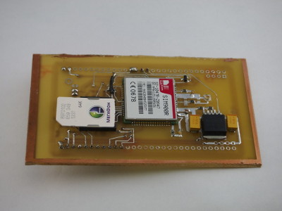
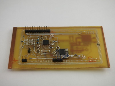
To make a board with a bunch of modules, we first made a separate debug board for each chip. Ordering production of such simple boards is a waste of time and money, so we made the first options ourselves at home. They chose between two technologies - LUT and sheet photoresist. The choice fell on a photoresist as a more technological method, independent of the skill of owning an iron.
In the process, we learned a lot of interesting things:
- how to get rid of the grain of the black areas on the photo mask
- how to ensure high-quality printing of narrow tracks (0.25 mm)
- that boards with an already applied double-sided photoresist, sold in Russia without any marking, are made using positive photoresist, and require the use of other reagents, unlike film negative photoresist.
Photos of our (terrible) debug boards made on the knee with a sheet photoresist:
NFC
Of all the modern RFID chips that support NFC and peer-to-peer connections, we chose the NXP PN532 chip. The NXP / Philips RFID chip family is time-tested and hardware supports the most common proprietary Mifare cards. In addition, the chip is supported by the actively developing libnfc library.
PN53x chips support connectivity via USB, UART, I2C and SPI buses. The UART and USB ports are very scarce, so we connected the chip via the SPI bus. All SPI devices use a common bus for data transfer, and only one GPIO output is spent on choosing which device to communicate with at the moment.
The “iron part” of the connection went without any surprises, but the software made us try to do it — the aforementioned libnfc library did not support SPI work.
In the process of implementing support for SPI, it turned out that the implementation of SPI in a chip from fellow NXPs is not very compatible with the standard and principles of working with SPI in Linux. It was necessary to apply, so to speak, non-standard technical solutions that use undocumented features of the chip.
WiFi
Price - the main thing that determined the choice of Wi-Fi module. But here was the trick. The cheapest Wi-Fi module on Digikey costs $ 17. But such a price comes in easy contradiction with the existence of cheap Chinese dongles for $ 3. No, everything is clear: the Chinese assembly, large volumes - but not 5 times! And this is even without taking into account the fact that in the second case they offer a ready-made device. Then we turned to the experience of already familiar comrades from Olimex: www.olimex.com/Products/Modules/Ethernet/MOD-WIFI-RTL8188 . There is an interesting name in the description for the module: RTL8188. It turned out that the Chinese produce a lot of ready-made modules on this Realtek chipset, which are mainly used in Chinese tablets and, for example, inside the well-known Chinese media center MK802. The modules come in different sizes, with and without an integrated antenna, for different mounting on the board. We used the most compact modules - without a built-in antenna, with solder pins on the board - just like those used in the MK802 (in the photo below right).
All modules are supplied exclusively to the Chinese market, we managed to find them only on taobao . Unfortunately, it is not customary to speak English there, but it can be understood that the module (at retail!) Costs 12.5 yuan, or 63 rubles 60 kopecks at the current rate.
It was not very easy to buy these modules in China, but in the end we got them.
Antennas
There are wireless modules - you need antennas. The first thing that came to mind was to draw the antennas with tracks right on the board. But there are some pitfalls: firstly, it is necessary to control the impedance of the antenna tracks, and secondly, a “exclusion zone” occurs around them, where other components and tracks cannot be placed - otherwise the gain will drop significantly. As a result, we obtain a significant increase in the size of the board with an indefinite gain.
The second option is a chip antenna, installed on the board. They are noticeably smaller, but still occupy precious space on the board, and the gain is small.
Therefore, we decided to use a simple solution - installation next to the wireless modules of the u.FL connectors. Here are these:
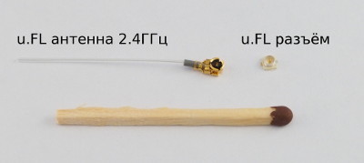
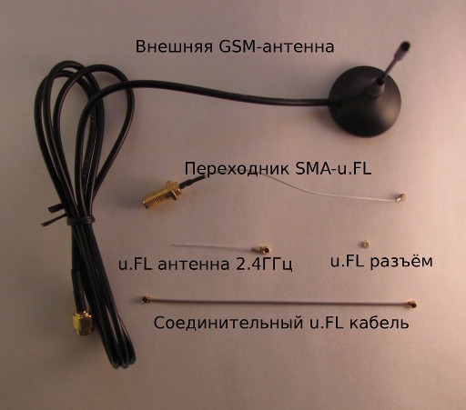
They connect either the antennas themselves (in the figure above - the simplest antenna for the 2.4 GHz band), or the thin coaxial cables that go to the antennas. The antenna itself can then be installed anywhere inside or outside the device.
Moreover, with the help of the adapter u.FL - SMA for mounting on the case, you can connect a large antenna with a full-sized SMA connector, for example:
Installing u.FL next to the corresponding modules is noticeably more convenient than installing SMA connectors directly on the board, since you need to draw a line with controlled impedance to the latter, which is very difficult and takes up a lot of space on the board.
And at the end we discovered a funny and pleasant property - Wi-Fi inside the apartment and GSM in the city are caught without any antenna, just on the u.FL-connector and the track that is suitable for it =)
UEXT
In fact, the UEXT connector is the major asset of the olimex company. Having invented the combination of three popular serial interfaces - SPI, I2C and UART, as well as power in one connector, olimex created a convenient way to add almost any wired or wireless interface or sensor to its debugging boards for different microcontrollers and microprocessors. What and took advantage of, having produced several dozen expansion devices - www.olimex.com/Products/Modules
We, though we create “a device without electrical tape”, we understand that some specific modules are sometimes easier to connect from the outside - especially if they are small, or they need special position in the finished device - such as www.olimex.com/ Products / Modules / Interface / MOD-IRDA . Therefore, on our board we made as many as two UEXT connectors.
Various photos of the finished board and prototypes can be viewed in the gallery .
Technical Specifications of Wiren Board
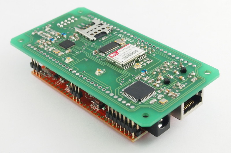
Here is what we have today:
- Two-storey computer, dimensions 50mm x 100mm x 23mm.
- First floor: our development board with peripherals, wireless and wired interfaces:
- GSM / GPRS SIMCOM SIM900R module. Connector for micro-SIM (or embedded-SIM module). The module can act as a modem, send SMS, and also supports a bunch of extensions, such as locating on towers, internal memory or remote control via SMS. U.FL jack for antenna.
- Wi-Fi on the chip RTL8188SU 802.11b / g / n. U.FL jack for antenna.
- Ethernet 10/100 on chip ENC424J600 , 8P8C-socket HanRun with built-in transformers and status LEDs
- GPS / GLONASS SIM68V module on the new MediaTek MT3333 chipset: TTFF 28 s., Support for downloaded ephemeris, selection of the GPS / GPS + GLONASS / GLONASS operation mode. U.FL jack for antenna.
- NFC on PN532 chip - read / write ISO / IEC 14443A / MIFARE cards, support for Mifare emulation, support for NFC Peer-to-Peer, NFCIP-1. Built-in antenna on the board.
- 2 UEXT connectors for connecting expansion cards - uart, spi, i2c or 7 gpio
- Second floor - Olinuxino Micro
- iMX233 ARM926J processor at 454Mhz
- 64 MB RAM
- Micro SD slot
- 19 free GPIO, divorced under the standard 2.54mm comb
- JTAG and SJTAG
- Linux 3.7.1, Debian 6.0, all necessary drivers and sample applications
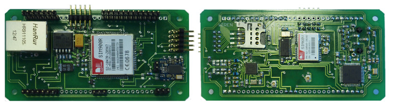
Ground floor Wiren Board from two sides:
We are not going to earn on retail sales for DIY, at least for now, and we would like to set the minimum possible price for the first batch during production in Russia. The price of production, even in Russia, greatly depends on the volume, so we open pre-order to represent in what quantities we need to pay.
Price also significantly depends on the configuration; We are aware that not everyone needs all the modules at once. We will analyze your orders and make several options for payment.
There are also modules on the pre-order page that were not mentioned in the article (DC-DC 7-40V, USB-host, RS232 / RS485 / RS422, relay, etc ...) - we tested them separately and we can add them to the first version fees, if they are claimed.
That's all for now. We will be glad to hear your advice and suggestions and answer questions in the comments!
Source: https://habr.com/ru/post/176357/
All Articles