10 tips for using AVR microcontrollers in motorized systems
Among those who are fond of electronics, one of the most popular etudes is the manufacture of a tracked robot. This topic is devoted to the mass of articles, including on Habré. The abundance of manuals, schemes and articles led me to believe that it would not be so difficult, and I also wanted to make such an excellent home-made product myself. It can be said that I was not lucky - in the process of work I ran into a lot of problems associated with the presence of engines. In the end, I managed to solve all these problems, but it took a lot of time. In this article, I offer some tips on designing circuits containing engines based on AVR microcontrollers. I had to make sure of the practical usefulness of all these tips on my own experience. Many tips, it seems to me, are suitable for other microcontrollers.
I have to say that when I started this project, my experience in electronics was minimal. Arduino by the time I had for quite some time, so I bought caterpillars and Tamiya dual gearboxes, an L293NE (driver driver) chip, and for a couple of evenings I created a label for Arduino with which this “robot” was cheerfully running around the room (albeit completely stupid) .
')
But I wanted more. Annoyed by the need to carry a separate battery "Krona" for powering the Arduino. And the very fact of using Arduino (I apologize to his fans!) Left an unpleasant feeling - it’s the same as assembling a machine from a designer (but from Arduino, a quite convenient programmer for AVR is obtained - I used it).
I had an Atmega8 , a Bluetooth module , an ultrasonic distance sensor , a three-axis accelerometer , L293NE and 74HC595 chips, and a whole host of resistors, capacitors and LEDs of all sorts and colors, as well as a photoresistor, a potentiometer, and an electromagnetic sound generator. I set myself the task of powering the engines and the logical part from one source - four AA 1.2V batteries. I saw radio-controlled tanks powered by such a source, so I had no doubt that this was possible.
I drew a circuit printed board and assembled it. I wrote a test firmware, made sure that the lights were flashing, Bluetooth was connecting, the beeper squeaked - and decided to give a test engine start. And plunged into the exciting world of working with AVR in a highly noisy environment.
Collector motors behave indecently. They make noise in a wide range of frequencies, and the start and jamming current is several times higher than the rated current at optimum load. In the work of my system, this was expressed in two manifestations:
Eliminating these problems took me a year and a half (not continuous work, of course!). In the end, everything worked, though the whole system had to be redone again.
All the considerations collected below are surely in one form or another present on the Internet. My main goal was to collect all the tips together: if such an article would have caught my eye earlier, it would save me a lot of time, money and peace of mind.
So, the tips.
That's all. In order not to be unfounded, in conclusion I will give a video demonstrating my robot in action. I hope that my article will be useful to someone and thank you for your attention!
I want to thank my friends, without whose help and advice I would have given up long ago, and this article would never have been written.
I have to say that when I started this project, my experience in electronics was minimal. Arduino by the time I had for quite some time, so I bought caterpillars and Tamiya dual gearboxes, an L293NE (driver driver) chip, and for a couple of evenings I created a label for Arduino with which this “robot” was cheerfully running around the room (albeit completely stupid) .
')
But I wanted more. Annoyed by the need to carry a separate battery "Krona" for powering the Arduino. And the very fact of using Arduino (I apologize to his fans!) Left an unpleasant feeling - it’s the same as assembling a machine from a designer (but from Arduino, a quite convenient programmer for AVR is obtained - I used it).
I had an Atmega8 , a Bluetooth module , an ultrasonic distance sensor , a three-axis accelerometer , L293NE and 74HC595 chips, and a whole host of resistors, capacitors and LEDs of all sorts and colors, as well as a photoresistor, a potentiometer, and an electromagnetic sound generator. I set myself the task of powering the engines and the logical part from one source - four AA 1.2V batteries. I saw radio-controlled tanks powered by such a source, so I had no doubt that this was possible.
I drew a circuit printed board and assembled it. I wrote a test firmware, made sure that the lights were flashing, Bluetooth was connecting, the beeper squeaked - and decided to give a test engine start. And plunged into the exciting world of working with AVR in a highly noisy environment.
Collector motors behave indecently. They make noise in a wide range of frequencies, and the start and jamming current is several times higher than the rated current at optimum load. In the work of my system, this was expressed in two manifestations:
- Spontaneous reset MK when you turn on the engine. It manifested itself more often when two engines were turned on at the same time, and especially when using PWM. The voltage drop was visible to the naked eye to reduce the brightness of the diodes;
- Failures in the MK. Hangup, skipping pieces of the program, spontaneous increase or decrease in clock frequency.
Eliminating these problems took me a year and a half (not continuous work, of course!). In the end, everything worked, though the whole system had to be redone again.
All the considerations collected below are surely in one form or another present on the Internet. My main goal was to collect all the tips together: if such an article would have caught my eye earlier, it would save me a lot of time, money and peace of mind.
So, the tips.
- Isolation of power
At the time of start-up, the motors consume much more current than in normal mode. For example, for motors that I use, the starting current is 1A. This leads to the fact that at startup there is an instantaneous voltage drop, often enough to reboot the microcontroller. To overcome this drawdown, it is necessary to decouple the power supply with a Schottky diode and a large capacitor.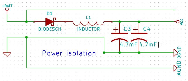
The Vcc line feeds the entire logical part of the circuit, and the power part of the engine driver is powered by the battery itself (the topmost line in the figure). When the supply voltage drops, the diode closes, and the current from the capacitors goes only to the Vcc line, which is what we need. The capacitance of the capacitor must be sufficient to maintain the logic power for the duration of the drawdown. I had two capacitors of 4.7mF. A series inductance turns the entire structure into an LC filter. - Separate ground into analog and digital parts.
The previous figure shows that the land is divided into two branches, AGND and DGND . In the diagram, this is not important, but in practice this means that the ground line serving the digital part and the ground of the engines should intersect only at one point as close as possible to the “minus” of the power supply.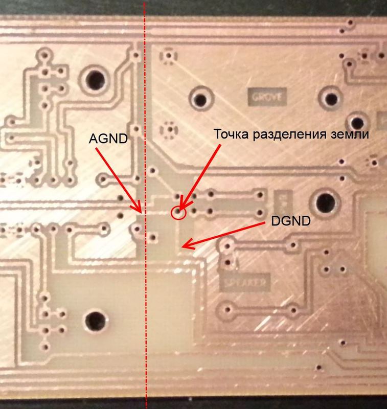
Of course, the land polygons must also be separated (the dash-dotted line in the figure). - Ensure the integrity of the mechanical parts.
I have not met this advice on the Internet, but in my case it turned out to be one of the decisive ones. On one of my engines, a plastic gear cracked on the shaft. This had practically no effect on the performance of the engine with a gearbox, so I noticed this only on an oscilloscope. At the moment the gearbox gear hit the crack, a slight wedging occurred, which resulted in an instantaneous increase in current consumption and the appearance of interference at the engine rotational speed. - Ground Quartz Resonator
The external clock circuit of the Atmega XTAL1 / XTAL2 serves as an excellent way for pickup. Therefore, if you use a quartz resonator in your project, it is likely that in a highly noisy environment the controller will start going crazy. In my case, this was reflected in a hangup, skipping pieces of the program, or a sudden change in the frequency of work up or down. To defeat this problem, I had enough advice from p. 2. However, if this did not help, try to ground the quartz by soldering a wire to digital ground on its case. Be careful - the quartz resonator is easy to disable with overheating. - Screen quartz resonator
I usually do a whole-earth fill on the board, but if you don’t like it, make at least a small ground around quartz and ballast capacitors, as told by Atmel. As in the previous paragraph, this will help protect the clocking line from interference. The same applies to the case if any analog line runs parallel to the logic - it makes sense to divide them with an earth ground. - Use the internal oscillator
Many AVR controllers are equipped with an internal oscillator. It is not as accurate as a quartz resonator, and also (for example, in the case of my Atmega8) often does not give the maximum clock frequency for the controller. But if nothing comes out at all, you can try using it. The first unsuccessful model of my robot worked stably only with the internal oscillator. - Electronics - the science of bad contact
Three times check all contacts for bad propayka. Avoid jumpers on the logic power line.
Contacts are good, but not where needed. I had a case where the robot worked fine, but it instantly rebooted when I tried to send something via Bluetooth. It turned out that Reset was shorted to the serial port line with a bit of solder. - Follow the manufacturers recommendations.
Almost all datasheets offer recommendations on body kit. Atmel even releases a separate document - AVR Hardware Design Considerations .
For example, the Atmega8 should be equipped with four capacitors ( Reset, Vcc, ARef, AVCC ) located as close as possible to the corresponding terminals. The reset must be pulled to power through a 10KΩ resistor, the main power supply ( Vcc ) is equipped with its own separate LC filter. Quartz and ballast capacitors should be located as close as possible to the MK. In general, any microcircuit should have its own separate capacitor, decoupling the power. - Place capacitors parallel to motor contacts.
Capacitors (100nF) should be soldered directly to the motor contacts. Actually, I knew this from the very beginning, and this advice here is just to complete the picture. - Lower Brown-out level
Brown-out - means a drop in voltage. Microcontrollers are equipped with such a drawdown detector. When it occurs, the microcontroller turns off. However, the level at which the shutdown occurs can be adjusted. For example, the Atmega8 has three options: detection is disabled, operation at 2.7V level, operation at 4.0V level. I do not advise turning off Brown-out detection completely, but lowering the trigger level may help. When I lowered the level to 2.7V, the system began to work much more stable.
That's all. In order not to be unfounded, in conclusion I will give a video demonstrating my robot in action. I hope that my article will be useful to someone and thank you for your attention!
Links
I want to thank my friends, without whose help and advice I would have given up long ago, and this article would never have been written.
Source: https://habr.com/ru/post/176203/
All Articles