Network Virtualization in Hyper-V. Customization
Last time, I described the concept and general architecture of Hyper-V Network Virtualization (NV), a Windows Server 2012 technology that provides virtualization at the network segment level. Today we will talk about setting up this technology using PowerShell and System Center 2012 SP1 Virtual Machine Manager (VMM).
On a host with the Hyper-V role deployed, there are several PowerShell cmdlets that can be used to configure the desired NV configuration. There are four main cmdlets:
As usual for PowerShell, there are similar commands with the prefixes Get-, Set-, Remove- to get the current settings, change and delete, respectively.
A couple more cmdlets, Get-NetVirtualizationGlobal and Set-NetVirtualizationGlobal, allow you to determine (and, accordingly, specify) whether an external Gateway is used to route traffic.
')
The easiest way to get acquainted with the listed cmdlets is to study and try to use in the test environment two example scripts developed by my colleagues. Each script contains detailed comments, a description of the modeled environment and an indication of the variables and constants that you need to replace with your own values. Find and download scripts here:
Checked personally, works. :) But I think it is obvious that on the scale of the data center, the manipulation of such scripts turns into an extremely difficult task. Therefore, I will discuss the configuration of NV using VMM in much more detail.
NV technology is part of Hyper-V in Windows Server 2012. System Center supports Windows Server 2012, starting with System Center 2012 SP1. Hereinafter we are talking about VMM from System Center 2012 SP1. I assume that VMM is already deployed, the Hyper-V hosts have been added to it, so I will pay attention only to those settings that are directly connected with NV.
Configuring NV using VMM consists of the following steps:
Consider each step in sequence.
Manually
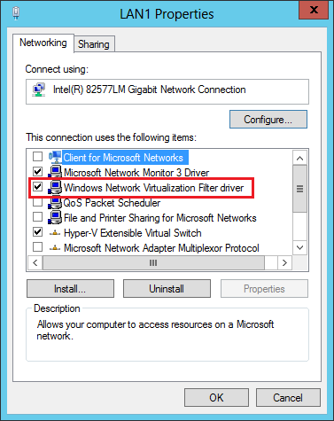
Let me remind you that the rules governing the operation of NV are set in the so-called virtualization policy. Certain settings specified in the virtualization policy are applied directly to network packets by the NDIS (Network Driver Interface Specification) level filter driver, called Windows Network Virtualization (WNV). This filter must be enabled on those Hyper-V hosts where you plan to use NV. This is done manually in the properties of the host's physical network adapter. I emphasize, namely the physical adapter, and not the virtual one, which, as a rule, is created when you configure the external switch Hyper-V.
Using the Logical Switch
As an alternative to manual configuration, you can use the logic switch mechanism introduced in VMM 2012 SP1. A more detailed description of the network settings in VMM can be found here in this post of George Hajiyev. I also briefly mention here that a logical switch is necessary in order to apply a given set of settings to network adapters and Hyper-V Extensible Switch switches on a set of hosts. You can find the settings described below in the “Fabric” section, the “Networking” subsection of the VMM console. In fact, there are three groups of settings in the logical switch: settings for physical network adapters of the hosts, settings for virtual network adapters of the VM (or rather, for the Hyper-V Extensible Switch ports to which the VMs are connected) and settings for the Hyper-V extensions Extensible Switch.
The first group of settings, namely it interests us the most, is set by creating a special profile called the Uplink Port Profile. In the profile you need to set the checkbox shown in the figure, thanks to which the WNV filter will be enabled in the future.

The second group of settings is defined by creating a profile called the Virtual Adapter Port Profile. In this profile, there are no settings directly related to NV, but it is there that you can set various switches security parameters (for example, DHCP Guard), performance (for example, IP Sec offload), traffic restrictions (Quality of Service).
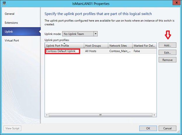
Well, then when creating a logical switch, you can specify the necessary extensions for the Hyper-V Extensible Switch, select the Virtual Adapter Port Profile and, most importantly, add the Uplink Port Profile in which we checked the checkbox “Enable Windows Network Virtualization”.
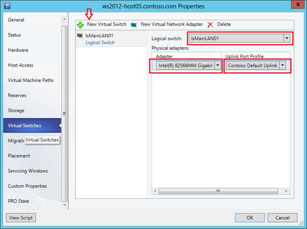
Thus, we have created some set of settings in the form of a logical switch. It remains to apply the created logical switch to the required Hyper-V hosts, and as a result, all the settings of this logical switch will be applied to the hosts. To do this, go to the Virtual Switches tab in the VMM console properties, click on “New Virtual Switch”, then “New Logical Switch” and select the necessary logical switch. We check that the same Uplink Port Profile is used for the required physical network adapter.
The next step is to enable NV for the required logical networks (Logical Networks). The logical networks in VMM allow the administrator to describe the physical network topology of the data center. This description further helps to significantly simplify the connection of the VM to the required network segments. Similarly, an Active Directory (AD) administrator, using sites and subnets, describes the physical network of an enterprise to optimize AD replication traffic. As applied to NV, VMM logical networks do not simply describe the real network topology, but also determine the space of PA addresses that will be used to transfer packets between VMs on different hosts.
So, let us imagine that IP addresses from the 192.168.1.0/24 range are used in the physical network. We also need to virtualize the networks of the two companies OJSC Blue and OJSC Krasny over this network. And both companies use the same range of IP-addresses, namely: 10.0.0.0/24.
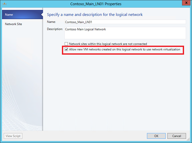
Create a logical network (menu button “Create Logical Network”) and on the first screen allow for this network NV:
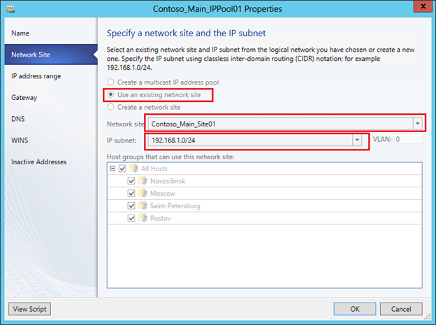
On the next screen, we create a site and indicate which host groups can use this site (actually located in it) and which IP subnets belong to this site.

Now for this logical network, you need to create a pool of IP addresses. In the context of NV, it is from this pool that VMM will allocate the PA address and associate it with the VM and the CA addresses configured within them. In the VMM console, click “Create IP Pool”, set the pool name and on the next screen specify for which site and which IP subnet we are creating the pool.
Then you need to set a range of IP addresses and, if necessary, reserve some addresses. For example:

On subsequent screens, you can specify the default gateway address, as well as DNS and WINS server addresses. Now that the logical network has been created and configured, it remains to indicate which Hyper-V hosts will be associated with it, or in other words, on which hosts VMs running that require access to this network can be running. In the properties of the hosts on the “Hardware” tab, you must select the host's network adapter and mark the corresponding logical network.

In the previous steps, we enabled the WNV filter and set up a logical network with a pool of IP addresses that will be used to allocate PA addresses. Thus, we prepared the physical infrastructure or, in the terminology of VMM, prepared Fabric. Now, on top of this infrastructure, you can create and virtualize arbitrary networks of customers of our data center. In this scenario, these clients, as you remember, are the companies of OJSC Blue and OJSC Krasny, using the same subnet 10.0.0.0/24.
With the release of SP1 for System Center 2012, VMM has a new type of object - a virtual machine network (VM Network), then just a “VM network”. First of all, this type of objects is intended for NV, although, as you will see later, even if NV is not used, at least one VM network needs to be created. Well, in our case, obviously, you need to create two VM networks for the “Blue” and “Red”, respectively. This process is very similar to creating a logical network - we create a VM network, define one or several sites in it with the indication of subnets, then create pools of IP addresses for subnets. But these pools will already be used to allocate CA addresses to virtual machines.
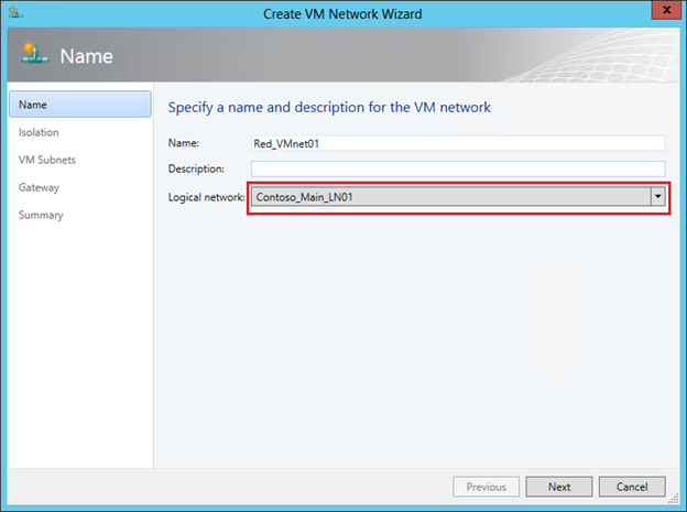
So, in the VMM console, go to the “VMs and Services” section and click the “Create VM Network” button. In the first window, specify the name of the network being created and select from the list a logical network over which this VM network will operate.
The next step is very important. Once we set up NV, select the top item. It will be available for selection only if NV support was enabled for the logical network indicated in the previous step, which we have already done.
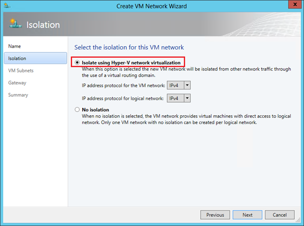
But here I would like to draw your attention to the second option “No Isolation”. If we select it, then we will indicate to VMM that the virtual machines of this network must be directly (without isolation) connected to the logical network. No additional settings in this case will not be required. The VMs created then will receive IP addresses from pools configured directly on the logical network. That is, you select the option “No Isolation” in the case when you do not need NV technology. And so it is natural that for each logical network you can create only one VM network without isolation.
We move further and in the next window we create a subnet (one or more) that is required by the client.

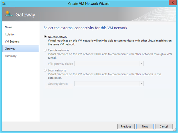
On the final screen of the wizard, we choose the way in which the VM of the network being created interacts with the outside world. Since we did not specifically set up an external gateway (this will be discussed in the next post), the choice here is one - “No Connectivity”, meaning that VMs can only interact within this VM network.
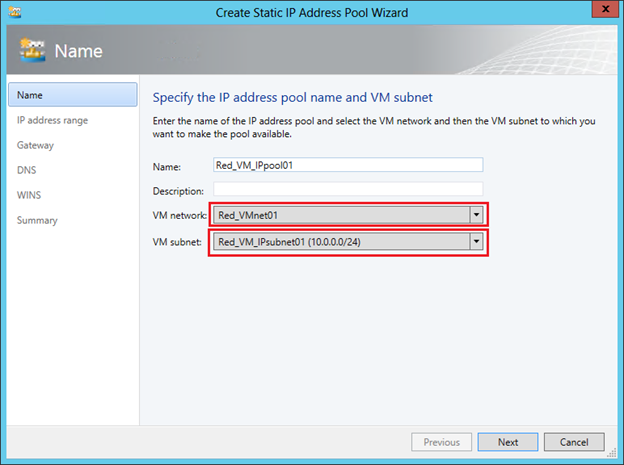
The last task of this stage is to configure address pools, that is, CA addresses, for the created VM network. In the VMM console, select the VM network and click “Create IP Pool”. On the first screen, we check that the necessary VM network and subnet are indicated:
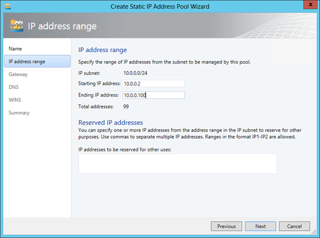
On the second set the range of IP addresses for VM:
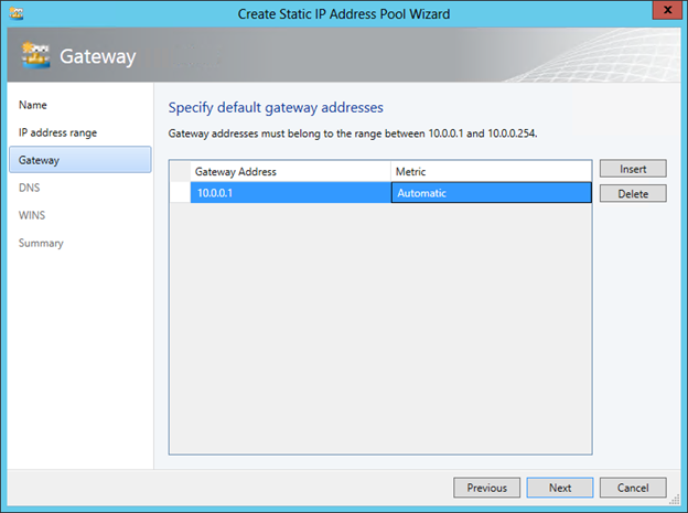
Specify the default gateway:
If necessary, we further specify the addresses of the DNS and WINS servers. The Red network is set up. We repeat the procedure for OJSC Blue and as a result we get the following picture:

The configuration of the actual network virtualization is now complete. If we recall the concept and architecture of NV, described by me in the previous post, it becomes clear that the VM Network corresponds to the term Customer Network, and VM Subnet corresponds to the term Virtual Subnet. Indeed, if using the Get-SCVMNetwork and Get-SCVMSubnet cmdlets to get information about the objects we just created, you will see the Routing Domain ID (RDID) in the response of the first cmdlet and the Virtual Subnet ID (VSID) of the second.
It remains to create VM templates for each network, and on their basis it will be possible to deploy the required number of “Blue” and “Red” VMs.
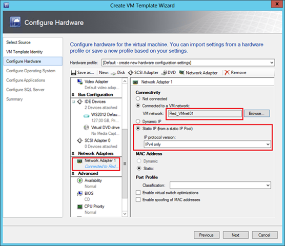
The procedure for creating templates for VMs that will be used by NV is completely standard and in essence is no different from creating templates for any other VMs. The only thing you need to pay attention to is that the virtual network adapter is connected to the correct VM network. For example, for the “Reds” template, this setting looks like this:
The “Static IP” parameter indicates to VMM that when creating a VM using this template, it is necessary to allocate a static IP address from the pool associated with the Red_VMnet01 network. And since NV is enabled for this network, the dedicated address will be the CA address. In addition, in the process of deploying a virtual machine, VMM will allocate a PA address from the pool associated with the corresponding logical network, associate a CA address / PA address pair and assign the necessary lines to the virtualization policy of the host where the VM will be deployed. If dynamic addressing is used in the data center, then the IP addresses can be allocated not from the VMM pools, but from the osprey of the DHCP server, and in this case, in the VM template, select the “Dynamic IP” option.
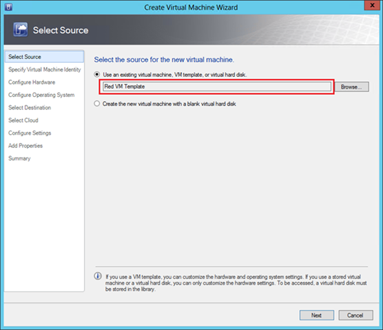
Now everything is completely ready, and you can deploy VMs based on prepared templates. Click the "Create Virtual Machine" button and select the desired template.
If all the above steps have been done without errors, then for the experiment you can create a pair of “Red” and a pair of “Blue” VMs on one or several Hyper-V physical hosts and make sure that the resulting VMs work with addresses from the network 10.0.0.0/24 perhaps even the IP addresses of the Blue and the Red coincide completely, but for all that, the Reds see each other and are completely isolated from the Blue.
Let's see what the response of one of the cmdlets mentioned at the beginning of the post looks like in my test environment. Below is the virtualization policy on one of the hosts:

In particular, it is clear that the CA address 10.0.0.2 (the first available address in the pool) was allocated to the Red-Web1 machine and associated with the PA address 192.168.1.52. The VM belongs to the subnet with VSID = 15184632 and belongs to the Customer Network with the identifier RDID = {206146EB-F035-4A19-A625-054C49DEEBD7}.
Another very interesting parameter “Rule” with the value “TranslationMethodEncap” says that NVGRE is used for IP address virtualization. This mechanism is the default when configuring NV in VMM and is recommended for most network virtualization scenarios. You can test the operation of the encapsulation mechanism by making the Red-Web1 ping machine at the address 10.0.0.3 and viewing the network monitor with the structure of the transmitted packets.
First, it can be observed that pings are transmitted as GRE packets between hosts with PA addresses 192.168.1.52 and 192.168.1.53. Secondly, the GRE header indicates that inside there is a packet of some protocol with the number 0x6558 (highlighted in blue in the figure), which is the NVGRE standard. Third, according to the NVGRE specification, the next 24 bits (circled in red) contain VSID. Indeed, if 0xE7B2F8 is converted to decimal, we get VSID = 15184632, which is the “Red” subnetwork.
Thus, we have configured and executed the Hyper-V Network Virtualization technology performance test. However, this is probably nothing more than laboratory tests, since we did not ensure the interaction of the VM with the outside world. We will talk about how it looks from an architectural point of view and how it is configured in the next post.
In the meantime, you can:
Hope the material was helpful.
Thank!
Configure Hyper-V Network Virtualization with PowerShell
On a host with the Hyper-V role deployed, there are several PowerShell cmdlets that can be used to configure the desired NV configuration. There are four main cmdlets:
- New-NetVirtualizationLookupRecord - creates an item in the virtualization policy table;
- New-NetVirtualizationProviderAddress - assigns the provider's address (Provider Address, PA) to the network interface;
- New-NetVirtualizationProviderRoute - sets the route for routing traffic on the physical network;
- New-NetVirtualizationCustomerRoute - sets the route for routing traffic in virtual networks.
As usual for PowerShell, there are similar commands with the prefixes Get-, Set-, Remove- to get the current settings, change and delete, respectively.
A couple more cmdlets, Get-NetVirtualizationGlobal and Set-NetVirtualizationGlobal, allow you to determine (and, accordingly, specify) whether an external Gateway is used to route traffic.
')
The easiest way to get acquainted with the listed cmdlets is to study and try to use in the test environment two example scripts developed by my colleagues. Each script contains detailed comments, a description of the modeled environment and an indication of the variables and constants that you need to replace with your own values. Find and download scripts here:
Checked personally, works. :) But I think it is obvious that on the scale of the data center, the manipulation of such scripts turns into an extremely difficult task. Therefore, I will discuss the configuration of NV using VMM in much more detail.
Configure Hyper-V Network Virtualization with System Center 2012 SP1 Virtual Machine Manager
NV technology is part of Hyper-V in Windows Server 2012. System Center supports Windows Server 2012, starting with System Center 2012 SP1. Hereinafter we are talking about VMM from System Center 2012 SP1. I assume that VMM is already deployed, the Hyper-V hosts have been added to it, so I will pay attention only to those settings that are directly connected with NV.
Configuring NV using VMM consists of the following steps:
- Enable the Windows Network Virtualization (WNV) filter on hosts with the Hyper-V role elevated.
- Inclusion of NV for the necessary logical networks.
- Creation of networks of virtual machines (VM Network) and pools of IP addresses.
- Creation of virtual machine templates (VM Template) with reference to necessary virtual machine networks.
- Deploy VMs using the templates prepared in Section 4.
Consider each step in sequence.
Enable the Windows Network Virtualization (WNV) filter
Manually
Let me remind you that the rules governing the operation of NV are set in the so-called virtualization policy. Certain settings specified in the virtualization policy are applied directly to network packets by the NDIS (Network Driver Interface Specification) level filter driver, called Windows Network Virtualization (WNV). This filter must be enabled on those Hyper-V hosts where you plan to use NV. This is done manually in the properties of the host's physical network adapter. I emphasize, namely the physical adapter, and not the virtual one, which, as a rule, is created when you configure the external switch Hyper-V.
Using the Logical Switch
As an alternative to manual configuration, you can use the logic switch mechanism introduced in VMM 2012 SP1. A more detailed description of the network settings in VMM can be found here in this post of George Hajiyev. I also briefly mention here that a logical switch is necessary in order to apply a given set of settings to network adapters and Hyper-V Extensible Switch switches on a set of hosts. You can find the settings described below in the “Fabric” section, the “Networking” subsection of the VMM console. In fact, there are three groups of settings in the logical switch: settings for physical network adapters of the hosts, settings for virtual network adapters of the VM (or rather, for the Hyper-V Extensible Switch ports to which the VMs are connected) and settings for the Hyper-V extensions Extensible Switch.
The first group of settings, namely it interests us the most, is set by creating a special profile called the Uplink Port Profile. In the profile you need to set the checkbox shown in the figure, thanks to which the WNV filter will be enabled in the future.
The second group of settings is defined by creating a profile called the Virtual Adapter Port Profile. In this profile, there are no settings directly related to NV, but it is there that you can set various switches security parameters (for example, DHCP Guard), performance (for example, IP Sec offload), traffic restrictions (Quality of Service).
Well, then when creating a logical switch, you can specify the necessary extensions for the Hyper-V Extensible Switch, select the Virtual Adapter Port Profile and, most importantly, add the Uplink Port Profile in which we checked the checkbox “Enable Windows Network Virtualization”.
Thus, we have created some set of settings in the form of a logical switch. It remains to apply the created logical switch to the required Hyper-V hosts, and as a result, all the settings of this logical switch will be applied to the hosts. To do this, go to the Virtual Switches tab in the VMM console properties, click on “New Virtual Switch”, then “New Logical Switch” and select the necessary logical switch. We check that the same Uplink Port Profile is used for the required physical network adapter.
Enable NV for logical networks
The next step is to enable NV for the required logical networks (Logical Networks). The logical networks in VMM allow the administrator to describe the physical network topology of the data center. This description further helps to significantly simplify the connection of the VM to the required network segments. Similarly, an Active Directory (AD) administrator, using sites and subnets, describes the physical network of an enterprise to optimize AD replication traffic. As applied to NV, VMM logical networks do not simply describe the real network topology, but also determine the space of PA addresses that will be used to transfer packets between VMs on different hosts.
So, let us imagine that IP addresses from the 192.168.1.0/24 range are used in the physical network. We also need to virtualize the networks of the two companies OJSC Blue and OJSC Krasny over this network. And both companies use the same range of IP-addresses, namely: 10.0.0.0/24.
Create a logical network (menu button “Create Logical Network”) and on the first screen allow for this network NV:
On the next screen, we create a site and indicate which host groups can use this site (actually located in it) and which IP subnets belong to this site.
Now for this logical network, you need to create a pool of IP addresses. In the context of NV, it is from this pool that VMM will allocate the PA address and associate it with the VM and the CA addresses configured within them. In the VMM console, click “Create IP Pool”, set the pool name and on the next screen specify for which site and which IP subnet we are creating the pool.
Then you need to set a range of IP addresses and, if necessary, reserve some addresses. For example:
On subsequent screens, you can specify the default gateway address, as well as DNS and WINS server addresses. Now that the logical network has been created and configured, it remains to indicate which Hyper-V hosts will be associated with it, or in other words, on which hosts VMs running that require access to this network can be running. In the properties of the hosts on the “Hardware” tab, you must select the host's network adapter and mark the corresponding logical network.
Creating virtual machine networks (VM Network) and IP address pools
In the previous steps, we enabled the WNV filter and set up a logical network with a pool of IP addresses that will be used to allocate PA addresses. Thus, we prepared the physical infrastructure or, in the terminology of VMM, prepared Fabric. Now, on top of this infrastructure, you can create and virtualize arbitrary networks of customers of our data center. In this scenario, these clients, as you remember, are the companies of OJSC Blue and OJSC Krasny, using the same subnet 10.0.0.0/24.
With the release of SP1 for System Center 2012, VMM has a new type of object - a virtual machine network (VM Network), then just a “VM network”. First of all, this type of objects is intended for NV, although, as you will see later, even if NV is not used, at least one VM network needs to be created. Well, in our case, obviously, you need to create two VM networks for the “Blue” and “Red”, respectively. This process is very similar to creating a logical network - we create a VM network, define one or several sites in it with the indication of subnets, then create pools of IP addresses for subnets. But these pools will already be used to allocate CA addresses to virtual machines.
So, in the VMM console, go to the “VMs and Services” section and click the “Create VM Network” button. In the first window, specify the name of the network being created and select from the list a logical network over which this VM network will operate.
The next step is very important. Once we set up NV, select the top item. It will be available for selection only if NV support was enabled for the logical network indicated in the previous step, which we have already done.
But here I would like to draw your attention to the second option “No Isolation”. If we select it, then we will indicate to VMM that the virtual machines of this network must be directly (without isolation) connected to the logical network. No additional settings in this case will not be required. The VMs created then will receive IP addresses from pools configured directly on the logical network. That is, you select the option “No Isolation” in the case when you do not need NV technology. And so it is natural that for each logical network you can create only one VM network without isolation.
We move further and in the next window we create a subnet (one or more) that is required by the client.
On the final screen of the wizard, we choose the way in which the VM of the network being created interacts with the outside world. Since we did not specifically set up an external gateway (this will be discussed in the next post), the choice here is one - “No Connectivity”, meaning that VMs can only interact within this VM network.
The last task of this stage is to configure address pools, that is, CA addresses, for the created VM network. In the VMM console, select the VM network and click “Create IP Pool”. On the first screen, we check that the necessary VM network and subnet are indicated:
On the second set the range of IP addresses for VM:
Specify the default gateway:
If necessary, we further specify the addresses of the DNS and WINS servers. The Red network is set up. We repeat the procedure for OJSC Blue and as a result we get the following picture:
The configuration of the actual network virtualization is now complete. If we recall the concept and architecture of NV, described by me in the previous post, it becomes clear that the VM Network corresponds to the term Customer Network, and VM Subnet corresponds to the term Virtual Subnet. Indeed, if using the Get-SCVMNetwork and Get-SCVMSubnet cmdlets to get information about the objects we just created, you will see the Routing Domain ID (RDID) in the response of the first cmdlet and the Virtual Subnet ID (VSID) of the second.
It remains to create VM templates for each network, and on their basis it will be possible to deploy the required number of “Blue” and “Red” VMs.
Creating virtual machine templates (VM Template)
The procedure for creating templates for VMs that will be used by NV is completely standard and in essence is no different from creating templates for any other VMs. The only thing you need to pay attention to is that the virtual network adapter is connected to the correct VM network. For example, for the “Reds” template, this setting looks like this:
The “Static IP” parameter indicates to VMM that when creating a VM using this template, it is necessary to allocate a static IP address from the pool associated with the Red_VMnet01 network. And since NV is enabled for this network, the dedicated address will be the CA address. In addition, in the process of deploying a virtual machine, VMM will allocate a PA address from the pool associated with the corresponding logical network, associate a CA address / PA address pair and assign the necessary lines to the virtualization policy of the host where the VM will be deployed. If dynamic addressing is used in the data center, then the IP addresses can be allocated not from the VMM pools, but from the osprey of the DHCP server, and in this case, in the VM template, select the “Dynamic IP” option.
Deploy VMs using prepared templates
Now everything is completely ready, and you can deploy VMs based on prepared templates. Click the "Create Virtual Machine" button and select the desired template.
Checking results
If all the above steps have been done without errors, then for the experiment you can create a pair of “Red” and a pair of “Blue” VMs on one or several Hyper-V physical hosts and make sure that the resulting VMs work with addresses from the network 10.0.0.0/24 perhaps even the IP addresses of the Blue and the Red coincide completely, but for all that, the Reds see each other and are completely isolated from the Blue.
Let's see what the response of one of the cmdlets mentioned at the beginning of the post looks like in my test environment. Below is the virtualization policy on one of the hosts:
In particular, it is clear that the CA address 10.0.0.2 (the first available address in the pool) was allocated to the Red-Web1 machine and associated with the PA address 192.168.1.52. The VM belongs to the subnet with VSID = 15184632 and belongs to the Customer Network with the identifier RDID = {206146EB-F035-4A19-A625-054C49DEEBD7}.
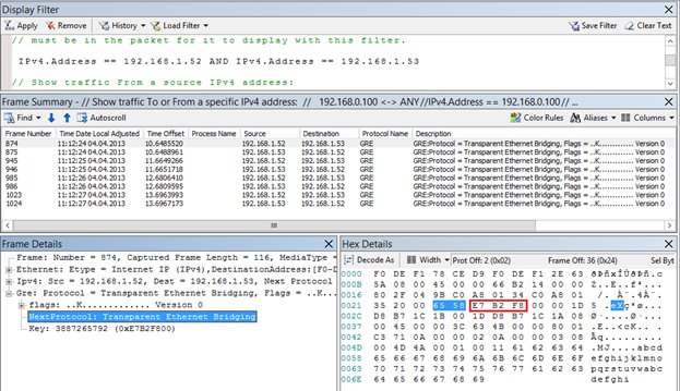
Another very interesting parameter “Rule” with the value “TranslationMethodEncap” says that NVGRE is used for IP address virtualization. This mechanism is the default when configuring NV in VMM and is recommended for most network virtualization scenarios. You can test the operation of the encapsulation mechanism by making the Red-Web1 ping machine at the address 10.0.0.3 and viewing the network monitor with the structure of the transmitted packets.
First, it can be observed that pings are transmitted as GRE packets between hosts with PA addresses 192.168.1.52 and 192.168.1.53. Secondly, the GRE header indicates that inside there is a packet of some protocol with the number 0x6558 (highlighted in blue in the figure), which is the NVGRE standard. Third, according to the NVGRE specification, the next 24 bits (circled in red) contain VSID. Indeed, if 0xE7B2F8 is converted to decimal, we get VSID = 15184632, which is the “Red” subnetwork.
Thus, we have configured and executed the Hyper-V Network Virtualization technology performance test. However, this is probably nothing more than laboratory tests, since we did not ensure the interaction of the VM with the outside world. We will talk about how it looks from an architectural point of view and how it is configured in the next post.
In the meantime, you can:
- view network virtualization in action in the first module of the course " New features of Windows Server 2012. Part 1. Virtualization, networks, storage ";
- Learn more about Hyper-V Network Virtualization in the third module of the course “ Windows Server 2012: Network Infrastructure ”;
- Download the original presentation (in English) with a detailed description of the packet flow process in NV.
Hope the material was helpful.
Thank!
Source: https://habr.com/ru/post/176039/
All Articles