Recommendations for planning and deployment of radio channels on Ubiquiti AirFiber equipment
The AirFiber equipment, introduced by ubiquiti in 2012, allows you to deploy point-to-point channels with a length of up to 14 km and a capacity of up to 750 Mbit fullduplex and unlimited packet capacity. Increasing the capacity of the channel several times with respect to conventional solutions (powerbridge, nanobridge) allows us to offer customers new tariff plans, as well as connect via the radio not only individual base stations, but also entire neighborhoods, merging network segments.
However, these serious applications require the correct approach to the planning and operation of a radio channel. After all, the cost of an error on a channel connecting a whole area is significantly higher than on a single client connection.
Before deploying a radio channel, it is necessary to carry out planning: make sure that there are radio visibility on the planned sites and the power system will allow you to get a reliable communication channel.
We recommend using the free RadioMobile program for a preliminary assessment. By entering the basic system parameters, gps coordinates and the planned installation height of the devices, you can calculate both the passage of the Fresnel zone and the energy budget of the radio channel.


Screens with radio car (calculation with EIRP 33)
Of course, the exact decision about the presence of direct visibility will only give exit to the installation site, because the program does not have maps of urban development, but you can make preliminary conclusions about visibility without leaving the office.
An important feature of AirFiber is the support of an adaptive modulation system, but the lack of QoS support.
That is, if the channel is designed with an insufficient supply of energy for operation at maximum modulation, in the rain the channel will not break, but will switch to a lower modulation. However, since there is no QoS support, the system will not be able to transmit only the highest priority traffic to the narrowed channel, but will try to transmit it all, as a result, there will be losses in all types of traffic.
For example, the channel in good weather has a capacity of 750 Mbps. In heavy rain, the capacity drops to 500 Mbps. Client load can be up to 50 Mbit voip traffic and 500 Mbit data traffic. During the rain, 50 Mbit or about 10% of the traffic will be lost.
For voice and video communications, such losses will lead to disconnection or unacceptable quality. The same picture will be observed if the traffic of users in good weather exceeds 750 Mbps.
Thus, to ensure maximum quality of service, it is necessary to have a sufficient radio channel capacity, an adequate supply of energy, or use systems that combine adaptive modulation and QoS.
What energy supply is required for a radio channel?
The answer depends on the length of the channel and the required availability ratio, that is, the percentage of time per year that the channel will operate at the estimated speed.
The availability of the channel is due to weather events that adversely affect the radio channel - rain, snow, and to a much lesser extent fog.
The longer our channel, the greater the attenuation will bring in precipitations of equal intensity.
Db \ km attenuation
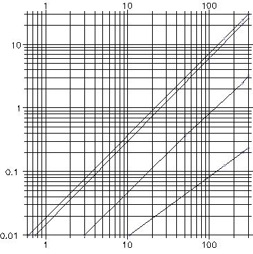
 GHz frequency
Attenuation of waves of various frequencies in the rain.
We see that the loss in the pouring shower of 41 mm / hour will be 6.37 dB per kilometer, the loss in a much more probable 12 mm / hour heavy rain of 1.7 dB / km
That is, for 5 km of the channel, the reserve for weather is 8.5, and for 12 km - already 20.4 dB, taking into account 12mm of rain over the entire length of the radio channel (of course, it is more likely that rain does not fall on the entire length of the link, then the insertion loss will be less).
This situation is typical for bands above 18 GHz, where the main limitation of the channel range is not fading in the atmosphere, but signal absorption in precipitation.
Accordingly, it is necessary to determine the rain of what intensity should be expected on the channel.
To do this, we use the recommendation of the ITU.
First we need to decide what channel accessibility we need.
Then we determine the rain zone of the installation site and find the rain intensity that is not exceeded with a given reliability (for example, if we need 99.95% reliability, we need to choose rain that does not occur more often than 0.05% of the time).
Then, for the found rain density, we calculate the attenuation introduced into the radio channel.
In fact, the possible range of radio communications is limited by the required availability of the radio channel — for example, availability of 99.995% is ensured for central Russia by 1.5 times less than the availability of 99.99%.


The probability of rain of a given density (central Russia - region E)

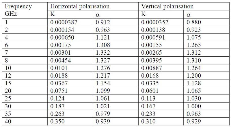
The formula for calculating rain attenuation


Coefficients for calculating rain attenuation
The table shows that for the calculation of the radio channel with availability of 99.9% we should take into account the additional attenuation in the rain with an intensity of 6 mm / hour, that is, 0.83 dB / km
If a channel with availability of 99.99% is needed, additional attenuation should be calculated for a rain density of 22 mm / hour, that is, 2.89 dB per km


The calculation of the distance, depending on the availability of the radio channel. Calculation for snr = 5
')
The time during which the channel will not function
Physical placement and equipment grounding
Any object located in the antenna array leads to signal re-reflection, which reduces the channel energy and can also lead to unstable system operation, especially at high speeds.
When choosing an installation site, take into account possible signal re-reflection from the underlying roof surface — mount the system so that the central lobe does not “touch” the roof, that is, closer to the building wall.
The radiation pattern of the transmitting antenna is 3.5 degrees, the receiving one is 2.5 degrees.
When deploying multiple channels on the same building, you must also take into account the possible interaction of networks.
Since AirFiber has only one pair of operating frequency ratings, two links on the same building can influence each other.
To reduce this effect:
If possible, install systems from different sides of shielding structures, for example, superstructures on the roof of a building.
TDD mode is more resistant to interference, but has a smaller capacity than FDD.
An important point in the installation is the grounding system.
The manufacturer recommends using a shielded twisted cable to connect the device to the power injector and a minimum 8AWG cross section of the device grounding cable.
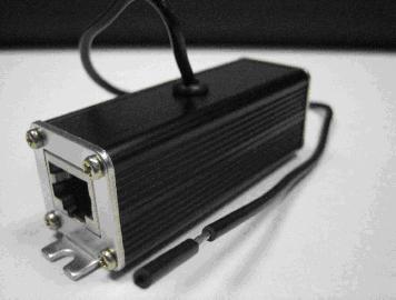
The device does not have a lightning arrester, we can offer lightning arresters of both internal and all-weather performance.


The surge protector must also be grounded.
When choosing a lightning arrester, make sure that it supports gigabit connectivity and protects all 4 twisted pairs.
Failure to comply with the grounding requirements may result in the failure of the injector or AirFiber itself. If your power injector has failed, you can replace it with a compatible model:
· Power 1 ampere or more, voltage 48-56 volts.
· Power supply at 4,5,7,8 core
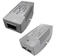
We can offer you a compatible model:

IDU-BS-G
Basic system setup
When installing the system will need to perform the following steps:
· Install the latest software version
· Change the addresses and vlan control devices to the ones you need
· Set master role on one device, slave on another
· Select FDD or TDD operation mode and frequency ratings.
·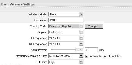
For long spans, we recommend using country code Dominican Republic, which allows you to increase output power by 7 dB

When you save the settings, the power will be reduced to 40 dbm Eirp, which is significantly more than 33 dbm by default.
· To improve channel stability, it is sometimes better to turn off the upper modulations if the energy supply for them is too small
· On very short radio channels (less than 1 km) it may be useful to reduce the RX GAIN
· In a typical configuration, device management is available only with the out of band management port. If you want to control the remote stations and control through the main port (in band control), select the appropriate option.
System alignment
Before installing the devices, check the calculated signal level, perhaps, the power of the devices should be reduced (in the case of short channels), or increased (to increase reliability on long channels) by selecting country code Dominican republic.
The system requires the presence of two people, one on each side of the channel.
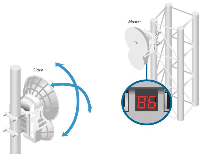
You can track the signal level on the device’s web menu or on the LED indicator.
The indicator on the device displays the signal level more quickly, but only shows the level of the receiving signal, that is, for proper alignment, communication with the far side will be required so that a colleague will inform the adjusting signal of the far side of the signal.
Adjustment of devices is carried out alternately, first at one end of the channel.
First, adjust the device configured in slave mode, since it starts to emit only after seeing the master.
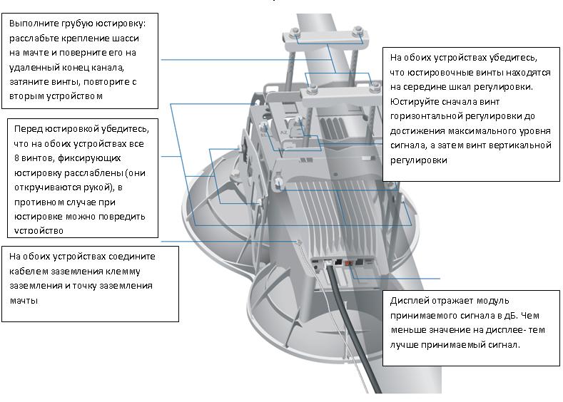
Install the mounting chassis in the position corresponding to the calculated azimuth.
Adjustment of the mount allows adjustment within + -10 degrees in the horizontal and vertical plane. Slowly turn the adjustment screws, adjusting the device first vertically and then horizontally.
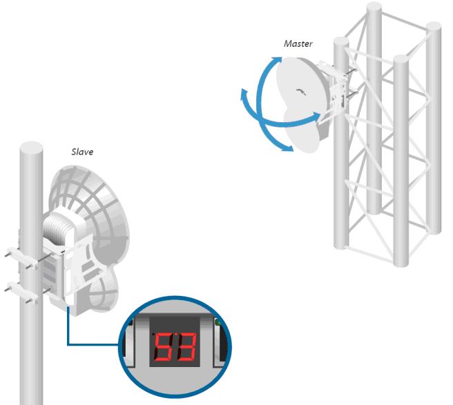


Adjust the Slave first and then the Master device.
At the end of the adjustment, carefully tighten the screws.
Check that the signal level has not deteriorated after tightening the fastener.
You can assess the correctness of the adjustment by the following criteria:
· Deviation of the signal level of both sides from the calculated one by no more than 3 dB
· The difference in the readings of the polarizations of one device is not more than 3 dB
· The signal level of devices differs from each other by no more than 1-2 dB
· When applying traffic, the channel speed of the system does not decrease below the estimated, there is no traffic loss
· Devices do not indicate that they are overloaded with an input signal (the oL indication on the device indicator).

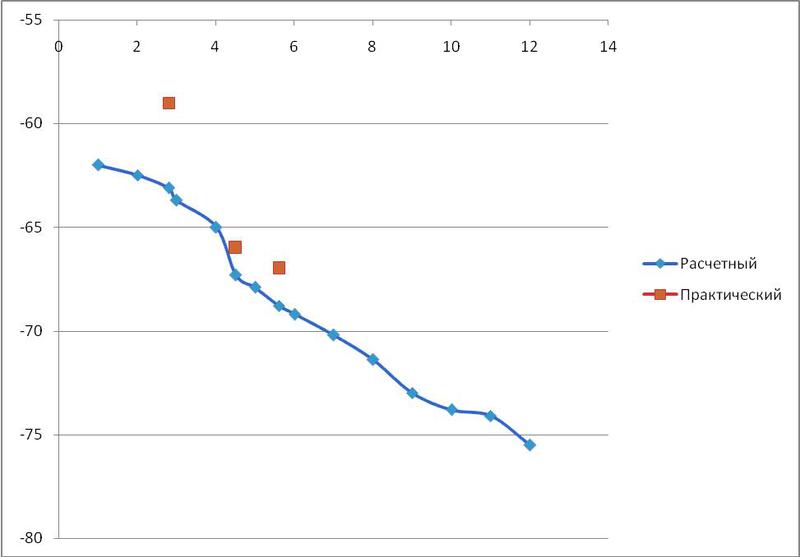
Test setups of the system, calculated and obtained values of signal levels (with EIRP of 30 dbm)
The main parameters of the device


The sensitivity of the device, depending on the speed (the speed is indicated in total in both directions)
However, these serious applications require the correct approach to the planning and operation of a radio channel. After all, the cost of an error on a channel connecting a whole area is significantly higher than on a single client connection.
Before deploying a radio channel, it is necessary to carry out planning: make sure that there are radio visibility on the planned sites and the power system will allow you to get a reliable communication channel.
We recommend using the free RadioMobile program for a preliminary assessment. By entering the basic system parameters, gps coordinates and the planned installation height of the devices, you can calculate both the passage of the Fresnel zone and the energy budget of the radio channel.
Screens with radio car (calculation with EIRP 33)
Of course, the exact decision about the presence of direct visibility will only give exit to the installation site, because the program does not have maps of urban development, but you can make preliminary conclusions about visibility without leaving the office.
An important feature of AirFiber is the support of an adaptive modulation system, but the lack of QoS support.
That is, if the channel is designed with an insufficient supply of energy for operation at maximum modulation, in the rain the channel will not break, but will switch to a lower modulation. However, since there is no QoS support, the system will not be able to transmit only the highest priority traffic to the narrowed channel, but will try to transmit it all, as a result, there will be losses in all types of traffic.
For example, the channel in good weather has a capacity of 750 Mbps. In heavy rain, the capacity drops to 500 Mbps. Client load can be up to 50 Mbit voip traffic and 500 Mbit data traffic. During the rain, 50 Mbit or about 10% of the traffic will be lost.
For voice and video communications, such losses will lead to disconnection or unacceptable quality. The same picture will be observed if the traffic of users in good weather exceeds 750 Mbps.
Thus, to ensure maximum quality of service, it is necessary to have a sufficient radio channel capacity, an adequate supply of energy, or use systems that combine adaptive modulation and QoS.
What energy supply is required for a radio channel?
The answer depends on the length of the channel and the required availability ratio, that is, the percentage of time per year that the channel will operate at the estimated speed.
The availability of the channel is due to weather events that adversely affect the radio channel - rain, snow, and to a much lesser extent fog.
The longer our channel, the greater the attenuation will bring in precipitations of equal intensity.
Db \ km attenuation
GHz frequencyAttenuation of waves of various frequencies in the rain.
We see that the loss in the pouring shower of 41 mm / hour will be 6.37 dB per kilometer, the loss in a much more probable 12 mm / hour heavy rain of 1.7 dB / km
That is, for 5 km of the channel, the reserve for weather is 8.5, and for 12 km - already 20.4 dB, taking into account 12mm of rain over the entire length of the radio channel (of course, it is more likely that rain does not fall on the entire length of the link, then the insertion loss will be less).
This situation is typical for bands above 18 GHz, where the main limitation of the channel range is not fading in the atmosphere, but signal absorption in precipitation.
Accordingly, it is necessary to determine the rain of what intensity should be expected on the channel.
To do this, we use the recommendation of the ITU.
First we need to decide what channel accessibility we need.
Then we determine the rain zone of the installation site and find the rain intensity that is not exceeded with a given reliability (for example, if we need 99.95% reliability, we need to choose rain that does not occur more often than 0.05% of the time).
Then, for the found rain density, we calculate the attenuation introduced into the radio channel.
In fact, the possible range of radio communications is limited by the required availability of the radio channel — for example, availability of 99.995% is ensured for central Russia by 1.5 times less than the availability of 99.99%.
The probability of rain of a given density (central Russia - region E)
The formula for calculating rain attenuation
Coefficients for calculating rain attenuation
The table shows that for the calculation of the radio channel with availability of 99.9% we should take into account the additional attenuation in the rain with an intensity of 6 mm / hour, that is, 0.83 dB / km
If a channel with availability of 99.99% is needed, additional attenuation should be calculated for a rain density of 22 mm / hour, that is, 2.89 dB per km
The calculation of the distance, depending on the availability of the radio channel. Calculation for snr = 5
| Estimated Reliability | 99% | 99.9% | 99.95% | 99.99% |
| Time remaining minutes per year | 5256 | 525.6 | 262.8 | 52,56 |
')
The time during which the channel will not function
Physical placement and equipment grounding
Any object located in the antenna array leads to signal re-reflection, which reduces the channel energy and can also lead to unstable system operation, especially at high speeds.
When choosing an installation site, take into account possible signal re-reflection from the underlying roof surface — mount the system so that the central lobe does not “touch” the roof, that is, closer to the building wall.
The radiation pattern of the transmitting antenna is 3.5 degrees, the receiving one is 2.5 degrees.
When deploying multiple channels on the same building, you must also take into account the possible interaction of networks.
Since AirFiber has only one pair of operating frequency ratings, two links on the same building can influence each other.
To reduce this effect:
If possible, install systems from different sides of shielding structures, for example, superstructures on the roof of a building.
TDD mode is more resistant to interference, but has a smaller capacity than FDD.
An important point in the installation is the grounding system.
The manufacturer recommends using a shielded twisted cable to connect the device to the power injector and a minimum 8AWG cross section of the device grounding cable.
The device does not have a lightning arrester, we can offer lightning arresters of both internal and all-weather performance.
The surge protector must also be grounded.
When choosing a lightning arrester, make sure that it supports gigabit connectivity and protects all 4 twisted pairs.
Failure to comply with the grounding requirements may result in the failure of the injector or AirFiber itself. If your power injector has failed, you can replace it with a compatible model:
· Power 1 ampere or more, voltage 48-56 volts.
· Power supply at 4,5,7,8 core
We can offer you a compatible model:
IDU-BS-G
Basic system setup
When installing the system will need to perform the following steps:
· Install the latest software version
· Change the addresses and vlan control devices to the ones you need
· Set master role on one device, slave on another
· Select FDD or TDD operation mode and frequency ratings.
·
For long spans, we recommend using country code Dominican Republic, which allows you to increase output power by 7 dB
When you save the settings, the power will be reduced to 40 dbm Eirp, which is significantly more than 33 dbm by default.
· To improve channel stability, it is sometimes better to turn off the upper modulations if the energy supply for them is too small
· On very short radio channels (less than 1 km) it may be useful to reduce the RX GAIN
· In a typical configuration, device management is available only with the out of band management port. If you want to control the remote stations and control through the main port (in band control), select the appropriate option.
System alignment
Before installing the devices, check the calculated signal level, perhaps, the power of the devices should be reduced (in the case of short channels), or increased (to increase reliability on long channels) by selecting country code Dominican republic.
The system requires the presence of two people, one on each side of the channel.
You can track the signal level on the device’s web menu or on the LED indicator.
The indicator on the device displays the signal level more quickly, but only shows the level of the receiving signal, that is, for proper alignment, communication with the far side will be required so that a colleague will inform the adjusting signal of the far side of the signal.
Adjustment of devices is carried out alternately, first at one end of the channel.
First, adjust the device configured in slave mode, since it starts to emit only after seeing the master.
Install the mounting chassis in the position corresponding to the calculated azimuth.
Adjustment of the mount allows adjustment within + -10 degrees in the horizontal and vertical plane. Slowly turn the adjustment screws, adjusting the device first vertically and then horizontally.
Adjust the Slave first and then the Master device.
At the end of the adjustment, carefully tighten the screws.
Check that the signal level has not deteriorated after tightening the fastener.
You can assess the correctness of the adjustment by the following criteria:
· Deviation of the signal level of both sides from the calculated one by no more than 3 dB
· The difference in the readings of the polarizations of one device is not more than 3 dB
· The signal level of devices differs from each other by no more than 1-2 dB
· When applying traffic, the channel speed of the system does not decrease below the estimated, there is no traffic loss
· Devices do not indicate that they are overloaded with an input signal (the oL indication on the device indicator).
Test setups of the system, calculated and obtained values of signal levels (with EIRP of 30 dbm)
The main parameters of the device
The sensitivity of the device, depending on the speed (the speed is indicated in total in both directions)
Source: https://habr.com/ru/post/175831/
All Articles