Ensuring Continuity (HA) with the OpenStack Platform: Topology Options
Posted by: Piotr Siwczak
When I developed my first OpenStack infrastructure, I could hardly find information about how to distribute its many components to the hardware. I studied a lot of documents, including the Rackspace Architecture Reference (which was previously posted on referencearchitecture.org , but now it looks like this link is outdated). I also looked at the design schemas in the OpenStack documentation. I have to admit that at that time I had only basic knowledge of how the components interact, so I stopped at a fairly simple scheme: one “control node” that included all the components, including the API services, nova-scheduler, Glance, Keystone database and RabbitMQ. Under the management of the site I put the farm “workhorses” - computing nodes. I also organized three networks: private (for traffic with a fixed IP address and server management), public (for traffic with a dynamic IP address) and for storage (for iSCSI traffic of the nova-volume service).
When I started working at Mirantis, I significantly changed my approach. I realized that all my ideas for creating a farm of dedicated compute nodes with one or two control nodes were incorrect. On the one hand, my approach was good in terms of component separation, but in practice we can easily mix and assemble working components without overloading OpenStack (for example, the nova-compute service with the nova-scheduler service on the same node). It turns out that the “control node” and the “compute node” in OpenStack can have different values depending on how flexibly the components of the OpenStack are distributed.
')
In general, it can be assumed that in each OpenStack installation there should be at least three types of nodes (and, possibly, the fourth) that my colleague Oleg Gelbuch described:
- Terminal node . This site is running load balancing and uninterrupted services, which may include load balancing and cluster creation software. A software and hardware complex in a network designed for load balancing can act as an end node. In a cluster, it is recommended to create at least two end nodes for redundancy.
- Managing site . This site hosts communication services that support the entire cloud, including a queue server, a database, a Horizon control panel, and possibly a monitoring system. This node can optionally have a nova-scheduler service and API servers that balance the load distribution to which the end node manages. In a cluster, you must create at least two control nodes for redundancy. The management node and the end node can be combined on the same physical server, but you must make changes to the configuration of the nova services — you must transfer them from the ports that the load balancer uses.
- Computing node . This node hosts the hypervisor and virtual instances that use its computational power. The compute node can also act as a network controller for the virtual instances located on it, if a multihost scheme is used. Also on the node can be placed not requiring a lot of resources internal OpenStack services, for example, balancer, glance-api, etc.
- Storage unit. It is required if you want to use the nova-volume service. This node hosts the nova-volume service. Also this node is the recipient of traffic via the iSCSI protocol.
Although the role of the end node is obvious — it usually houses a software load balancer or a hardware-software complex designed to evenly distribute traffic across OpenStack components and ensure uninterrupted operation — the control and compute nodes can be configured differently, starting from “thick” control nodes where all internal OpenStack service processes (scheduler, API services, Glance, Keystone, RabbitMQ, MySQL) are located to “thin”, on which only the services responsible are located for maintaining the state of OpenStack (RabbitMQ and MySQL). Then the compute nodes can take over some of the internal OpenStack service processes, due to the location of API services and scheduler instances on them.
Mirantis has experience deploying service topologies for a wide range of customers. Here I will briefly discuss these topologies, illustrate them with diagrams, and also describe various ways to deploy OpenStack. (The separation of services can be continued further.)
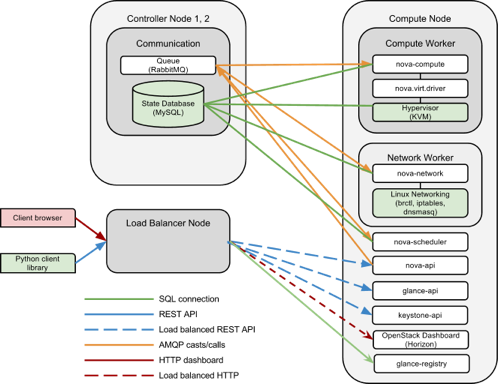
In this deployment option, a hardware-software complex designed for load balancing is used as an end node for connecting OpenStack services. API servers, schedulers, and nova-scheduler service instances are deployed on compute nodes, and glance-registry and Horizon instances are deployed on control nodes.
All Nova components are web services that do not store state information; their scaling is possible by adding additional instances to the pool (for details, see the Mirantis article on scaling API services). Therefore, we can simply distribute these components across the compute node farm. The database and the message queue server can be deployed on both control nodes using clusters (this method will be described in detail in one of the following articles). And even better: on the management node, there are now platform components that are not internal OpenStack services (MySQL and RabbitMQ are standard Linux demons). Thus, the cloud administrator can transfer their administration to an external entity, the Database Team, to a dedicated RabbitMQ cluster. Thus, the central control node is eliminated and in our configuration there remains a set of computing nodes / API nodes that can be linearly scaled.
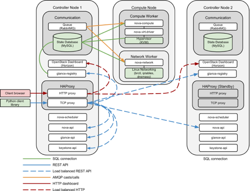
In this deployment configuration, we replace the hardware load balancer with an end node that distributes traffic across the services farm. Another significant difference from the previous architecture is the placement of API services on control nodes instead of compute nodes. In fact, the control nodes have become “thicker”, and the computing nodes have become “thinner.” In addition, both control nodes operate with switching from the operating mode to the standby mode. Control node failure conditions can be determined using tools such as Pacemaker and Corosync / Heartbeat.

In this deployment, the end nodes are combined with control nodes. API services and nova-scheduler services are installed on control nodes, and scaling of the control node is possible by adding nodes and reconfiguring HAProxy. Two instances of HAProxy are deployed to ensure uninterrupted operation, and the definition of failures and the switching of a specific HAProxy from standby to working mode can be performed using tools such as Pacemaker and Corosync / Heartbeat.
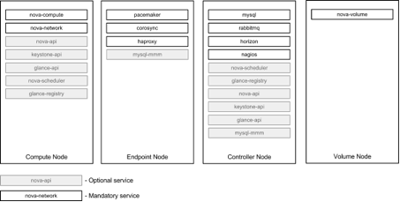
I illustrated the distribution of services across physical nodes that Mirantis implemented for various clients. However, the system administrator can combine and combine services in different ways, depending on your needs. The diagram below shows — based on the experience of Mirantis — the various ways that the OpenStack services are distributed across different types of nodes.
The main load on the end node is the network subsystem. A node of this type requires high CPU performance and high network bandwidth. Also for the operation of a node, if possible, it is useful to combine network interfaces for redundancy and increase network bandwidth.
The cloud management node may be “thick” or “thin.” The minimum configuration includes OpenStack components that maintain the state of the system: the database and the AMQP server. The redundant configuration of a cloud management node requires at least two nodes; we recommend using network interface binding for network redundancy and RAID1 or RAID10 arrays for backup storage. The minimum configuration for the control node:
- One 6-core processor
- RAM 8 GB
- 2 hard disks on 1 terabyte in software RAID1 array
Compute nodes require maximum available memory and processor power. The disk system requirements are not very hard, although the use of SSD disks can significantly improve performance (since the host instance file systems are usually located on a local disk). In a non-redundant configuration, it is possible to use one disk, and in case of failure, replace the disk and return the server back to the cluster as a new compute node.
In fact, the hardware requirements for a computational node depend on the user's assessment of the average parameters of the virtual object and the desired density of objects on one physical node.
Storage management nodes provide virtual servers with persistent data storage as blocks. Since block data storage usually contains vital data, it is very important to ensure its availability and data integrity. The storage node must contain at least six disks. We recommend installing the operating system on a redundant disk array (RAID1). The remaining four disks are assembled into a RAID5 array or a RAID10 array, depending on the configuration of the management RAID node.
Block storage is shared via the iSCSI protocol, which means a high load on the network subsystem. We recommend at least two related interfaces for data exchange using iSCSI protocol, possibly configured specifically for exchanging traffic of this type (jumbo frames, etc.)
The topology of the OpenStack network is similar to a regular data center. (Other Mirantis articles provide a more detailed overview of the construction of the OpenStack network: FlatDHCPManager, VlanManager.) Internal data exchange between instances takes place over a fixed IP address (private data center network). This network interfaces with the public one through the network address translator and the firewall provided by the nova-network component. To communicate with the outside world, a public network with floating IP addresses is used (demilitarized data center zone). To manage the servers, a management network (IPMI / BM (Intelligent Platform Management interface / baseboard management controller) data center network) is used. Also, if necessary, you can use a separate storage network for nova-volume services (data center storage network). The diagram below shows the cloud topology (however, in this case, iSCSI traffic is combined with management traffic). The two networks on eth1 are tagged interfaces on top of eth1, using the 802.1q kernel module.

The public network has the following purpose:
- Make instances with floating IP addresses visible to the rest of the world.
- Make visible the virtual IP addresses of the end node that clients use to connect to the OpenStack API services.
The public network is usually isolated from private and management networks. The public / corporate network is one class C network from the cloud owner's public network (global routing is used for public clouds).
A private network is a network segment that is connected to all compute nodes; all bridges on the compute nodes are connected to this network. It is on this network that instances of compute nodes exchange traffic to fixed IP addresses. If VlanManager is used, this network is further segmented into isolated VLANs, one per project existing in the cloud. Each VLAN contains a network of IP addresses allocated to this project and integrates the virtual machines that belong to this project. If the FlatDHCP scheme is used, virtual machines from different projects use a single virtual local area network and a single IP address space.
The management network unites all cluster nodes and is used to exchange internal data between the components of an OpenStack cluster. This network should be isolated from private and public networks for security reasons. The management network can also be used for iSCSI communication between the compute node and the storage node, if the traffic is not too heavy. This is a separate class C network from a private IP address range (without global routing).
An iSCSI network is not required if the workload does not include a significant amount of data that is being processed by block storage devices. In case of significant load, we recommend iSCSI data exchange over a dedicated connection in order to avoid confusion with control traffic and to ensure the possibility of optimizing iSCSI traffic, for example, jumbo frames, queue length distribution for interfaces, etc.
In uninterrupted mode (HA), all central components of OpenStack need to be placed behind the load balancer. To do this, you can use dedicated hardware or an end node. The end node runs load and load balancing software; On the same IP address is the OpenStack service process farm. The table below illustrates the location of services in various networks with a load balancer:
OpenStack deployment can be organized in various ways - it provides scalability and availability. This fact is not obvious from the documentation that is on the network (at least, it was not obvious to me), and I observed several cases where system administrators were sure that they necessarily needed a central control node.
This is not true; in fact, installations without a central control node are possible with the database and messaging server located off-platform.
In the case of a distributed architecture, it is necessary to carefully distribute traffic across several instances of the service, as well as ensure the replication of resources with state fixation (such as MySQL and RabbitMQ). The OpenStack team has not yet mentioned this in its documentation, so Mirantis will try to fill this gap in a future series of articles on scaling the platform and API services.
Original article (in English): www.mirantis.com/blog/117072
When I developed my first OpenStack infrastructure, I could hardly find information about how to distribute its many components to the hardware. I studied a lot of documents, including the Rackspace Architecture Reference (which was previously posted on referencearchitecture.org , but now it looks like this link is outdated). I also looked at the design schemas in the OpenStack documentation. I have to admit that at that time I had only basic knowledge of how the components interact, so I stopped at a fairly simple scheme: one “control node” that included all the components, including the API services, nova-scheduler, Glance, Keystone database and RabbitMQ. Under the management of the site I put the farm “workhorses” - computing nodes. I also organized three networks: private (for traffic with a fixed IP address and server management), public (for traffic with a dynamic IP address) and for storage (for iSCSI traffic of the nova-volume service).
When I started working at Mirantis, I significantly changed my approach. I realized that all my ideas for creating a farm of dedicated compute nodes with one or two control nodes were incorrect. On the one hand, my approach was good in terms of component separation, but in practice we can easily mix and assemble working components without overloading OpenStack (for example, the nova-compute service with the nova-scheduler service on the same node). It turns out that the “control node” and the “compute node” in OpenStack can have different values depending on how flexibly the components of the OpenStack are distributed.
')
In general, it can be assumed that in each OpenStack installation there should be at least three types of nodes (and, possibly, the fourth) that my colleague Oleg Gelbuch described:
- Terminal node . This site is running load balancing and uninterrupted services, which may include load balancing and cluster creation software. A software and hardware complex in a network designed for load balancing can act as an end node. In a cluster, it is recommended to create at least two end nodes for redundancy.
- Managing site . This site hosts communication services that support the entire cloud, including a queue server, a database, a Horizon control panel, and possibly a monitoring system. This node can optionally have a nova-scheduler service and API servers that balance the load distribution to which the end node manages. In a cluster, you must create at least two control nodes for redundancy. The management node and the end node can be combined on the same physical server, but you must make changes to the configuration of the nova services — you must transfer them from the ports that the load balancer uses.
- Computing node . This node hosts the hypervisor and virtual instances that use its computational power. The compute node can also act as a network controller for the virtual instances located on it, if a multihost scheme is used. Also on the node can be placed not requiring a lot of resources internal OpenStack services, for example, balancer, glance-api, etc.
- Storage unit. It is required if you want to use the nova-volume service. This node hosts the nova-volume service. Also this node is the recipient of traffic via the iSCSI protocol.
Although the role of the end node is obvious — it usually houses a software load balancer or a hardware-software complex designed to evenly distribute traffic across OpenStack components and ensure uninterrupted operation — the control and compute nodes can be configured differently, starting from “thick” control nodes where all internal OpenStack service processes (scheduler, API services, Glance, Keystone, RabbitMQ, MySQL) are located to “thin”, on which only the services responsible are located for maintaining the state of OpenStack (RabbitMQ and MySQL). Then the compute nodes can take over some of the internal OpenStack service processes, due to the location of API services and scheduler instances on them.
Mirantis has experience deploying service topologies for a wide range of customers. Here I will briefly discuss these topologies, illustrate them with diagrams, and also describe various ways to deploy OpenStack. (The separation of services can be continued further.)
Hardware Load Balancer Topology
In this deployment option, a hardware-software complex designed for load balancing is used as an end node for connecting OpenStack services. API servers, schedulers, and nova-scheduler service instances are deployed on compute nodes, and glance-registry and Horizon instances are deployed on control nodes.
All Nova components are web services that do not store state information; their scaling is possible by adding additional instances to the pool (for details, see the Mirantis article on scaling API services). Therefore, we can simply distribute these components across the compute node farm. The database and the message queue server can be deployed on both control nodes using clusters (this method will be described in detail in one of the following articles). And even better: on the management node, there are now platform components that are not internal OpenStack services (MySQL and RabbitMQ are standard Linux demons). Thus, the cloud administrator can transfer their administration to an external entity, the Database Team, to a dedicated RabbitMQ cluster. Thus, the central control node is eliminated and in our configuration there remains a set of computing nodes / API nodes that can be linearly scaled.
Dedicated endpoint topology
In this deployment configuration, we replace the hardware load balancer with an end node that distributes traffic across the services farm. Another significant difference from the previous architecture is the placement of API services on control nodes instead of compute nodes. In fact, the control nodes have become “thicker”, and the computing nodes have become “thinner.” In addition, both control nodes operate with switching from the operating mode to the standby mode. Control node failure conditions can be determined using tools such as Pacemaker and Corosync / Heartbeat.
Simple redundant topology topology
In this deployment, the end nodes are combined with control nodes. API services and nova-scheduler services are installed on control nodes, and scaling of the control node is possible by adding nodes and reconfiguring HAProxy. Two instances of HAProxy are deployed to ensure uninterrupted operation, and the definition of failures and the switching of a specific HAProxy from standby to working mode can be performed using tools such as Pacemaker and Corosync / Heartbeat.
Many ways to distribute services
I illustrated the distribution of services across physical nodes that Mirantis implemented for various clients. However, the system administrator can combine and combine services in different ways, depending on your needs. The diagram below shows — based on the experience of Mirantis — the various ways that the OpenStack services are distributed across different types of nodes.
Hardware requirements for different types of nodes
The main load on the end node is the network subsystem. A node of this type requires high CPU performance and high network bandwidth. Also for the operation of a node, if possible, it is useful to combine network interfaces for redundancy and increase network bandwidth.
The cloud management node may be “thick” or “thin.” The minimum configuration includes OpenStack components that maintain the state of the system: the database and the AMQP server. The redundant configuration of a cloud management node requires at least two nodes; we recommend using network interface binding for network redundancy and RAID1 or RAID10 arrays for backup storage. The minimum configuration for the control node:
- One 6-core processor
- RAM 8 GB
- 2 hard disks on 1 terabyte in software RAID1 array
Compute nodes require maximum available memory and processor power. The disk system requirements are not very hard, although the use of SSD disks can significantly improve performance (since the host instance file systems are usually located on a local disk). In a non-redundant configuration, it is possible to use one disk, and in case of failure, replace the disk and return the server back to the cluster as a new compute node.
In fact, the hardware requirements for a computational node depend on the user's assessment of the average parameters of the virtual object and the desired density of objects on one physical node.
Storage management nodes provide virtual servers with persistent data storage as blocks. Since block data storage usually contains vital data, it is very important to ensure its availability and data integrity. The storage node must contain at least six disks. We recommend installing the operating system on a redundant disk array (RAID1). The remaining four disks are assembled into a RAID5 array or a RAID10 array, depending on the configuration of the management RAID node.
Block storage is shared via the iSCSI protocol, which means a high load on the network subsystem. We recommend at least two related interfaces for data exchange using iSCSI protocol, possibly configured specifically for exchanging traffic of this type (jumbo frames, etc.)
Network topology
The topology of the OpenStack network is similar to a regular data center. (Other Mirantis articles provide a more detailed overview of the construction of the OpenStack network: FlatDHCPManager, VlanManager.) Internal data exchange between instances takes place over a fixed IP address (private data center network). This network interfaces with the public one through the network address translator and the firewall provided by the nova-network component. To communicate with the outside world, a public network with floating IP addresses is used (demilitarized data center zone). To manage the servers, a management network (IPMI / BM (Intelligent Platform Management interface / baseboard management controller) data center network) is used. Also, if necessary, you can use a separate storage network for nova-volume services (data center storage network). The diagram below shows the cloud topology (however, in this case, iSCSI traffic is combined with management traffic). The two networks on eth1 are tagged interfaces on top of eth1, using the 802.1q kernel module.
The public network has the following purpose:
- Make instances with floating IP addresses visible to the rest of the world.
- Make visible the virtual IP addresses of the end node that clients use to connect to the OpenStack API services.
The public network is usually isolated from private and management networks. The public / corporate network is one class C network from the cloud owner's public network (global routing is used for public clouds).
A private network is a network segment that is connected to all compute nodes; all bridges on the compute nodes are connected to this network. It is on this network that instances of compute nodes exchange traffic to fixed IP addresses. If VlanManager is used, this network is further segmented into isolated VLANs, one per project existing in the cloud. Each VLAN contains a network of IP addresses allocated to this project and integrates the virtual machines that belong to this project. If the FlatDHCP scheme is used, virtual machines from different projects use a single virtual local area network and a single IP address space.
The management network unites all cluster nodes and is used to exchange internal data between the components of an OpenStack cluster. This network should be isolated from private and public networks for security reasons. The management network can also be used for iSCSI communication between the compute node and the storage node, if the traffic is not too heavy. This is a separate class C network from a private IP address range (without global routing).
An iSCSI network is not required if the workload does not include a significant amount of data that is being processed by block storage devices. In case of significant load, we recommend iSCSI data exchange over a dedicated connection in order to avoid confusion with control traffic and to ensure the possibility of optimizing iSCSI traffic, for example, jumbo frames, queue length distribution for interfaces, etc.
Utility processes Openstack vs. network
In uninterrupted mode (HA), all central components of OpenStack need to be placed behind the load balancer. To do this, you can use dedicated hardware or an end node. The end node runs load and load balancing software; On the same IP address is the OpenStack service process farm. The table below illustrates the location of services in various networks with a load balancer:
| OpenStack component | Location on site | Network location | Notes |
| nova-api, glance-api, glance registry keystone api Horizon | manager/ computational | Public network | Since users (end-points of the API) access these services directly, it is logical to locate them in the public network. |
| nova-scheduler | manager/ computational | Control network | |
| nova-compute | computational | Control network | |
| nova-network | manager/ computational | Control network | |
| Mysql | manager | Control network | Including replication / uninterrupted traffic (HA) |
| RabbitMQ | manager | Control network | Including rabbitMQ cluster traffic |
| nova-volume | storage node | Control network | |
| iSCSI | storage node | Management network (dedicated local network) or dedicated network iSCSI | In the case of a large amount of traffic block storage should use a dedicated network. |
findings
OpenStack deployment can be organized in various ways - it provides scalability and availability. This fact is not obvious from the documentation that is on the network (at least, it was not obvious to me), and I observed several cases where system administrators were sure that they necessarily needed a central control node.
This is not true; in fact, installations without a central control node are possible with the database and messaging server located off-platform.
In the case of a distributed architecture, it is necessary to carefully distribute traffic across several instances of the service, as well as ensure the replication of resources with state fixation (such as MySQL and RabbitMQ). The OpenStack team has not yet mentioned this in its documentation, so Mirantis will try to fill this gap in a future series of articles on scaling the platform and API services.
Original article (in English): www.mirantis.com/blog/117072
Source: https://habr.com/ru/post/175807/
All Articles