Arduino radar
It so happened that I caught the eye of the arduino with a number of sensors. Having played enough with blinks and analog reads, of course, I came to the thought of buying my own board. Having run a quick glance at the list of ready-made shilds, I opened the ebay and ordered Funduino Mega2560 (analog of the arduino mega 2560 ), and a number of additional devices to it.
Among the most interesting shidovs ordered was a color TFT display with a resolution of 320x240, having a 16-bit bus and a resistive touchscreen. As it turned out later, the display had to be connected to the Mega via a transition shield, but having missed this moment, the adapter was not ordered, and the thirst for adventure forced the soldering iron into the hands and solder the “daddy” connector to the “mother”. As a result, with the help of a serious pile of wires and a certain number of nerve cells, the display wound up, the standard library picked up and experiments began. Actually, the results of the latter will be discussed.
')

Now it is "mom"
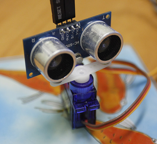
Having an ultrasonic distance sensor and a color display in my hands, it was completely sad to deal exclusively with the output of alphanumeric values of distances, therefore the idea of graphical realization of the “seen” sensor was only a matter of time. Modern industrial radar stations for scanning in 2D space, the antenna is placed on a platform capable of rotating around its axis. I didn’t come up with anything else, but simply glued an ultrasonic sensor onto a hot-melt glue to a serva.
Another would be a 10mW laser and - be afraid of a fly !!!
So that myradar ULS was more stable, the resulting unit was decided to glue to the glass stand for glasses. For experiments, it turned out to be more than enough, and the repeatability is good. So, once again, the principle of operation. The servomotor rotates the distance sensor mounted on it left and right. Every moment of a change in the angle of a servy, is accompanied by working pulses of the sensor. In other words, each corner of the servo corresponds to its sensor readings. Further, these data are translated into a readable form by the library of the ultrasonic sensor and in accordance with the angle and the sensor readings, a dot is drawn on the display.
A small anima illustrating the principle of operation.
I made the code as simple as possible. However, in a more stable version, a sensor error corrector has been added. Periodically, UZ provides outrageous data, say, adds 2000mm to this value. and the previous and subsequent values are within the normal range. So analyzing the neighboring data, the code corrects the error.
However, it was not without problems. It turned out that the current of the USB output is not enough for a full-fledged powering only the arduino and the display, not to mention the server with the ultrasonic sensor. I had to power the board from 9 volt power supply unit. However, even in this case, the ultrasound gave out incorrect data, and its measurement limit was limited to 50 cm in depth. And this is not counting the mass of interference mixed into the final data from the sensor. The source of interference, as it turned out, was a servo, which, when rotated, gave serious guidance to the ultrasonic sensor. As a result, the servo, I powered from the second power supply, connecting only the negative wire with a common circuit. Despite all the measures taken, the pickup partially remained, which is noticeable both on the data from the sensor and on the image from the display.
Among the most interesting shidovs ordered was a color TFT display with a resolution of 320x240, having a 16-bit bus and a resistive touchscreen. As it turned out later, the display had to be connected to the Mega via a transition shield, but having missed this moment, the adapter was not ordered, and the thirst for adventure forced the soldering iron into the hands and solder the “daddy” connector to the “mother”. As a result, with the help of a serious pile of wires and a certain number of nerve cells, the display wound up, the standard library picked up and experiments began. Actually, the results of the latter will be discussed.
')
Now it is "mom"
Having an ultrasonic distance sensor and a color display in my hands, it was completely sad to deal exclusively with the output of alphanumeric values of distances, therefore the idea of graphical realization of the “seen” sensor was only a matter of time. Modern industrial radar stations for scanning in 2D space, the antenna is placed on a platform capable of rotating around its axis. I didn’t come up with anything else, but simply glued an ultrasonic sensor onto a hot-melt glue to a serva.
Another would be a 10mW laser and - be afraid of a fly !!!
So that my
A small anima illustrating the principle of operation.
I made the code as simple as possible. However, in a more stable version, a sensor error corrector has been added. Periodically, UZ provides outrageous data, say, adds 2000mm to this value. and the previous and subsequent values are within the normal range. So analyzing the neighboring data, the code corrects the error.
#include <UTFT.h>// #include <Servo.h>// #include <Ultrasonic.h>// Servo servoMain; // Ultrasonic ultrasonic(5, 6);// UTFT myGLCD(ITDB32S, 38,39,40,41);// int i = 0; // int dist_cm = 0;// boolean trig = false; // void setup() { servoMain.attach(3); // 3 myGLCD.InitLCD(); // myGLCD.clrScr();// Serial.begin(9600);// . } void loop() { if(!trig){i++;}// trig false i if(trig){i--;}// trig true i dist_cm = ultrasonic.Ranging(CM); // myGLCD.setColor(55,255,55); // myGLCD.fillCircle(i, (99 - dist_cm)*2, 2);// 2 , x = i, y = if(i==319) // i { trig = true;// trig true myGLCD.clrScr();// } if(i==0) { trig = false;// trig false myGLCD.clrScr();// } delay(5);// 5. servoMain.write(i/2); // i/2 delay(5);// 5. } However, it was not without problems. It turned out that the current of the USB output is not enough for a full-fledged powering only the arduino and the display, not to mention the server with the ultrasonic sensor. I had to power the board from 9 volt power supply unit. However, even in this case, the ultrasound gave out incorrect data, and its measurement limit was limited to 50 cm in depth. And this is not counting the mass of interference mixed into the final data from the sensor. The source of interference, as it turned out, was a servo, which, when rotated, gave serious guidance to the ultrasonic sensor. As a result, the servo, I powered from the second power supply, connecting only the negative wire with a common circuit. Despite all the measures taken, the pickup partially remained, which is noticeable both on the data from the sensor and on the image from the display.
Source: https://habr.com/ru/post/175495/
All Articles