Solder the connector for 4 hours. Accelerated video
I often do sniffing RS-232 swapping. Usually they do it like this - you need two com-ports, one of which listens to the exchange “there”, and the other - “here”. Two years for this purpose served the device, assembled from a pair of modules and MAX232 soldered on the breadboard. The device allows you to work with conventional RS-232 levels, and with TTL, the choice of mode of operation is provided by a bunch of jumpers.
The problem was that the data is buffered before being transferred via USB to the computer, which causes the data sequence to be distorted during sniffing. Let's say we sniff this exchange:
- Hello!
- Great!
- Will you have a beer?
- No, today I just drink juice.
And we see this:
- Hello!
- Great! No, today I just drink juice.
- Will you have a beer?
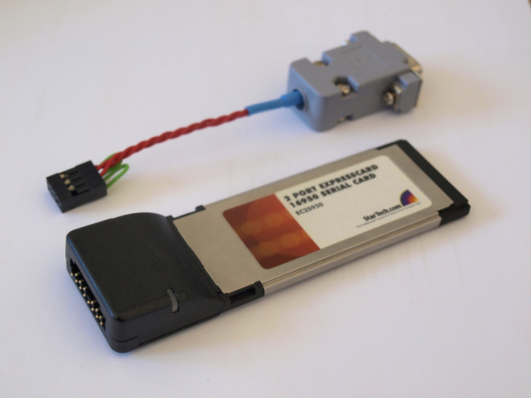
Since it happens on a laptop, then all hope is for an Express Card com-port card. Moreover, it should be an “honest” com port, not a USB (Express Card connector also hides USB). At the time of writing, the 2-port card on the Oxford chipset on ebay.com cost about $ 35 with delivery.
')
I don’t remember what prevented me from simply buying one, it seems they were twice as expensive at that moment. I bought another one, without cable and for $ 25. The plan was to stick a connector of standard 2.54 mm pins to it and at the same time bring signals with TTL levels to this connector.
In the TTL card, the signal is broken between the controller (in this case, the OX16PCI952) and the level converter, two wires are output to the external connector. If we need a TTL level, we simply connect to the desired pin. If the RS-232 level is needed, then we hang a jumper on the external connector, the signal returns to the converter and in the RS-232 form comes out on the other pin of the connector.
2 ports * 2 signals * 2 wires for each = 8 wires that need to be soldered. This is for TTL signals. And 4 more for RS-232. I somehow thought at first that there shouldn't be so many of them :)
If habrageers are interested, I can replenish the article with a detailed description of the process, but for now let everyone tell the video. There are 4 hours, 20 times accelerated to 12 minutes. In general, the process took two (incomplete) days off. And one more evening (not reflected in the video) on the tap-off and soldering of everything anew - when it turned out that the board, in the places where I drilled it, is fed in the middle layers.
I cannot recommend this to anyone to repeat - during the same time it was possible to make a printed scarf with the help of LUT and make a neat external level converter on the planar MAX232. And here, after all, it is a very non-technological process - to raise legs, to feed into the platforms under them. Especially when you consider that in the process of soldering, one contact pad fell off altogether and had to go to the controller's foot (and its legs had a 0.4 mm pitch). But nevertheless, the goal was achieved and it turned out such a device:
 "
"
The problem was that the data is buffered before being transferred via USB to the computer, which causes the data sequence to be distorted during sniffing. Let's say we sniff this exchange:
- Hello!
- Great!
- Will you have a beer?
- No, today I just drink juice.
And we see this:
- Hello!
- Great! No, today I just drink juice.
- Will you have a beer?
Since it happens on a laptop, then all hope is for an Express Card com-port card. Moreover, it should be an “honest” com port, not a USB (Express Card connector also hides USB). At the time of writing, the 2-port card on the Oxford chipset on ebay.com cost about $ 35 with delivery.
')
I don’t remember what prevented me from simply buying one, it seems they were twice as expensive at that moment. I bought another one, without cable and for $ 25. The plan was to stick a connector of standard 2.54 mm pins to it and at the same time bring signals with TTL levels to this connector.
In the TTL card, the signal is broken between the controller (in this case, the OX16PCI952) and the level converter, two wires are output to the external connector. If we need a TTL level, we simply connect to the desired pin. If the RS-232 level is needed, then we hang a jumper on the external connector, the signal returns to the converter and in the RS-232 form comes out on the other pin of the connector.
2 ports * 2 signals * 2 wires for each = 8 wires that need to be soldered. This is for TTL signals. And 4 more for RS-232. I somehow thought at first that there shouldn't be so many of them :)
If habrageers are interested, I can replenish the article with a detailed description of the process, but for now let everyone tell the video. There are 4 hours, 20 times accelerated to 12 minutes. In general, the process took two (incomplete) days off. And one more evening (not reflected in the video) on the tap-off and soldering of everything anew - when it turned out that the board, in the places where I drilled it, is fed in the middle layers.
I cannot recommend this to anyone to repeat - during the same time it was possible to make a printed scarf with the help of LUT and make a neat external level converter on the planar MAX232. And here, after all, it is a very non-technological process - to raise legs, to feed into the platforms under them. Especially when you consider that in the process of soldering, one contact pad fell off altogether and had to go to the controller's foot (and its legs had a 0.4 mm pitch). But nevertheless, the goal was achieved and it turned out such a device:
"Source: https://habr.com/ru/post/175397/
All Articles