Mobile phone do it yourself. Part 1
Recently on Habré was a post about how some craftsmen from Massachusetts Technological created a "self-made" mobile phone. I think it's time to prove that our Monsieur also knows a lot about ... er ... in exquisite pleasures.
So, I present to your attention a mobile phone assembled practically “on the knee”!
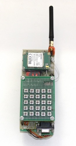
I ask all interested under cat. A lot of pictures!
Due to the significant amount of material the article will be in two parts. The first part will describe the hardware, and the second part will examine the AT commands of the module and give examples of their use.
So, let's begin.
')
The “heart” of the phone is the Quectel M10 GSM module, which has wide functionality, including both telephone communication and data transmission. The device also has a power source that allows you to power the device from a 12V source (for example, a lead-acid battery), an RS-232 interface, a keyboard, an antenna, a SIM card holder and a headset connector.
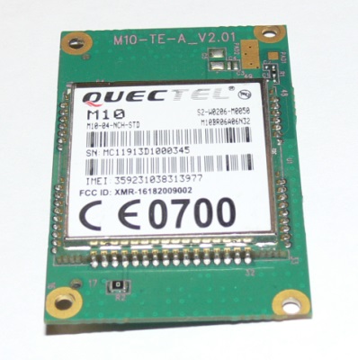
M10-TE-A Module
Let's start with the power supply
The power supply provides power to the device with voltages of + 4.1V (current up to 2A), + 5V (current up to 500 mA), + 3.3V (current up to 100 mA). A voltage of 4.1V is needed to power the GSM module. GSM-modules have very high demands on the power supply. The power supply of the module must have a voltage from 3.4 V to 4.5 V at a current to 2 A, while the amplitude of the ripple with an abrupt change in the load current from zero to the maximum should not exceed 400 mV. In fig. 1 shows the permissible amplitude of the supply voltage ripples when the module is operating.

Fig. 1. Permissible ripple voltage during operation of the GSM-module.
Initially it was assumed that the device would contain a microcontroller with a 3.3 V supply voltage and a display, for supplying the backlight of which a voltage of 5V would be needed. At this stage, assume that the current through channel 5B does not exceed 0.5A. The input voltage of the power source is chosen equal to 12V. The electrical circuit is shown in Fig. 2
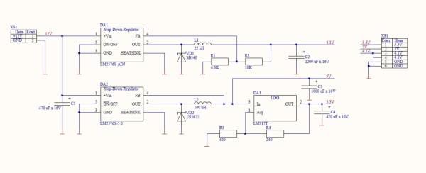
Fig. 2. Power supply circuit ( pdf )
The scheme is not without flaws, and basically uses what I had "at hand". Of course, this solution is not very suitable for serial production, but it is quite suitable for experiments. We will not dwell in detail here on the operation of this circuit and on the calculation of the nominal, since they are elementary and are described in detail in the documentation for the corresponding chips.
So, we assemble the circuit on the breadboard (Fig. 3) and carry out tests under load, while controlling the temperature of the fuel elements. Tests passed successfully.
If you are going to use only the GSM module, without other nodes, then the sources + 5V and 3.3V are not needed.
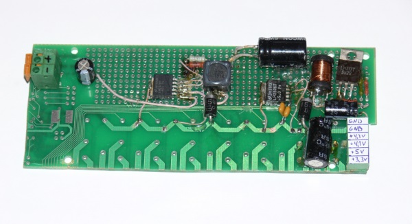
Fig.3. Power supply board
The layout of the keyboard board is almost unchanged from the documentation for the module. However, after it was assembled, it turned out that the row of buttons is not supported by this version of the module. In principle, it is possible not to connect the keyboard to the module at all, all actions with the module can be performed using AT commands via the UART.
Keyboard diagram is shown in Fig. 4. Diodes are used to protect the module from static voltage.
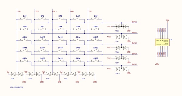
Fig.4. Keyboard layout ( pdf )
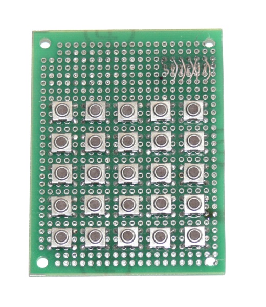
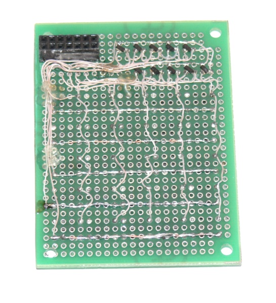
Fig.5. Keyboard board
Go to the main board.
Since the device is assembled on a breadboard, I decided not to use the Quectel M10 module, which is soldered on the board, but its “derivative” module with the M10-TE-A module, which has an IDC connector with a 1.27 mm pitch (a two-row socket). The antenna is connected to a special small connector (GSC) via an adapter GSC-SMA. In the serial device, on a normal board, of course, it makes sense to use the usual M10 module. It should be borne in mind that M10 and M10-TE-A have different numbering of conclusions, so the scheme will also have to be adjusted.
So, the circuit board:
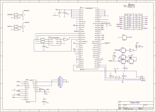
Fig.6. GSM circuit board ( pdf )
And the board itself:
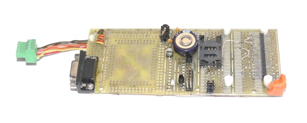
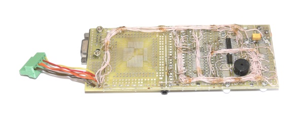
Fig.7. GSM fee
The scheme contains a module, a SIM card holder, a headset connector, a keyboard connector and a pair of chips: an RS-232 interface and an auxiliary chip for connecting a piezo-radiator and an LED to the module. There are no special circuit design delights, almost everything is taken from the documentation for the module.
A couple more words about connecting the keyboard. Since the ROW3, ROW4 and COL4 columns are not used by the module, I decided to use them for the on and off buttons of the module.
The phone also has no display. Although the module has pins for direct connection of the display, it still cannot be connected, since this function (like many others) is disabled for modules that go on sale.
To power the real-time clock, an ionistor is used (a capacitor of 1F capacity, a large round piece on the board). If the clock is not needed, you can not install it.
So, it's time to assemble our designer:
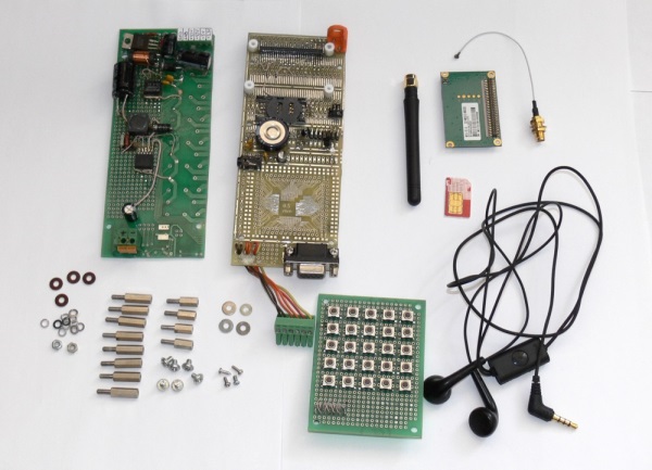
Fig. 8. Everything is ready for assembly
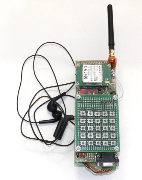
Fig. 9. Telephone assembly
Now you can insert a SIM-card, connect power, connect your phone to a computer via a COM-port and start researching AT commands.
A few words about the budget.
Quectel M10-TE-A Module 665.64 .
Antenna 120 p.
SIM Card Holder SCV-W2523X-06-LF 21,80
Cable adapter GSC-SMA - 161,86r.
The remaining components are found within a radius of three meters.
The next part will look at the AT commands supported by the module.
Unfortunately, the manufacturer’s website contains far from complete information about the module. Most of the pdf files are not publicly available; nevertheless, some of them can be found on the network. I took the trouble to collect these files and upload them for download.
1. M10_ATC_V1.03.pdf - guide to the AT commands of the module M10
2. M10_EVB_UGD_V1.01.pdf - description of the debugging board based on the M10 module
3. M10_GSM_Module_Specification.pdf - a brief description of the module M10
4. M10_HD_V1.02.pdf - Hardware Design
5. M10-TE-A_HD_V1.01.pdf - description of the board based on the M10 module
6. GPRS_Startup_UGD_V101.pdf - installation of a modem in Windows
7. GSM_UART_AN_V100.pdf - connect devices to the UART
8. RF LAYOUT_AN_V1.0.pdf - antenna connection to the module
9. GSM_Location_ATC_V10.pdf - request for coordinates and time
Documents describing work with FTP, HTTP, MMS, SMTP and TCP / IP respectively:
10. GSM_FTP_ATC_V100.pdf
11. GSM_HTTP_ATC_V100.pdf
12. GSM_MMS_ATC_V101.pdf
13. GSM_SMTP_ATC_V11.pdf
14. GSM_TCPIP_AN_V101.pdf
Ps. If your links do not open, try downloading here:
PDF (one archive)
Schemes (one archive)
So, I present to your attention a mobile phone assembled practically “on the knee”!
I ask all interested under cat. A lot of pictures!
Due to the significant amount of material the article will be in two parts. The first part will describe the hardware, and the second part will examine the AT commands of the module and give examples of their use.
So, let's begin.
')
Short description
The “heart” of the phone is the Quectel M10 GSM module, which has wide functionality, including both telephone communication and data transmission. The device also has a power source that allows you to power the device from a 12V source (for example, a lead-acid battery), an RS-232 interface, a keyboard, an antenna, a SIM card holder and a headset connector.
M10-TE-A Module
Let's start with the power supply
Power Supply
The power supply provides power to the device with voltages of + 4.1V (current up to 2A), + 5V (current up to 500 mA), + 3.3V (current up to 100 mA). A voltage of 4.1V is needed to power the GSM module. GSM-modules have very high demands on the power supply. The power supply of the module must have a voltage from 3.4 V to 4.5 V at a current to 2 A, while the amplitude of the ripple with an abrupt change in the load current from zero to the maximum should not exceed 400 mV. In fig. 1 shows the permissible amplitude of the supply voltage ripples when the module is operating.
Fig. 1. Permissible ripple voltage during operation of the GSM-module.
Initially it was assumed that the device would contain a microcontroller with a 3.3 V supply voltage and a display, for supplying the backlight of which a voltage of 5V would be needed. At this stage, assume that the current through channel 5B does not exceed 0.5A. The input voltage of the power source is chosen equal to 12V. The electrical circuit is shown in Fig. 2
Fig. 2. Power supply circuit ( pdf )
The scheme is not without flaws, and basically uses what I had "at hand". Of course, this solution is not very suitable for serial production, but it is quite suitable for experiments. We will not dwell in detail here on the operation of this circuit and on the calculation of the nominal, since they are elementary and are described in detail in the documentation for the corresponding chips.
So, we assemble the circuit on the breadboard (Fig. 3) and carry out tests under load, while controlling the temperature of the fuel elements. Tests passed successfully.
If you are going to use only the GSM module, without other nodes, then the sources + 5V and 3.3V are not needed.
Fig.3. Power supply board
Keyboard board
The layout of the keyboard board is almost unchanged from the documentation for the module. However, after it was assembled, it turned out that the row of buttons is not supported by this version of the module. In principle, it is possible not to connect the keyboard to the module at all, all actions with the module can be performed using AT commands via the UART.
Keyboard diagram is shown in Fig. 4. Diodes are used to protect the module from static voltage.
Fig.4. Keyboard layout ( pdf )
Fig.5. Keyboard board
GSM module fee
Go to the main board.
Since the device is assembled on a breadboard, I decided not to use the Quectel M10 module, which is soldered on the board, but its “derivative” module with the M10-TE-A module, which has an IDC connector with a 1.27 mm pitch (a two-row socket). The antenna is connected to a special small connector (GSC) via an adapter GSC-SMA. In the serial device, on a normal board, of course, it makes sense to use the usual M10 module. It should be borne in mind that M10 and M10-TE-A have different numbering of conclusions, so the scheme will also have to be adjusted.
So, the circuit board:
Fig.6. GSM circuit board ( pdf )
And the board itself:
Fig.7. GSM fee
The scheme contains a module, a SIM card holder, a headset connector, a keyboard connector and a pair of chips: an RS-232 interface and an auxiliary chip for connecting a piezo-radiator and an LED to the module. There are no special circuit design delights, almost everything is taken from the documentation for the module.
A couple more words about connecting the keyboard. Since the ROW3, ROW4 and COL4 columns are not used by the module, I decided to use them for the on and off buttons of the module.
The phone also has no display. Although the module has pins for direct connection of the display, it still cannot be connected, since this function (like many others) is disabled for modules that go on sale.
To power the real-time clock, an ionistor is used (a capacitor of 1F capacity, a large round piece on the board). If the clock is not needed, you can not install it.
Assembly
So, it's time to assemble our designer:
Fig. 8. Everything is ready for assembly
Fig. 9. Telephone assembly
Now you can insert a SIM-card, connect power, connect your phone to a computer via a COM-port and start researching AT commands.
A few words about the budget.
Budget
Quectel M10-TE-A Module 665.64 .
Antenna 120 p.
SIM Card Holder SCV-W2523X-06-LF 21,80
Cable adapter GSC-SMA - 161,86r.
The remaining components are found within a radius of three meters.
In conclusion, the first part
The next part will look at the AT commands supported by the module.
Links
Unfortunately, the manufacturer’s website contains far from complete information about the module. Most of the pdf files are not publicly available; nevertheless, some of them can be found on the network. I took the trouble to collect these files and upload them for download.
1. M10_ATC_V1.03.pdf - guide to the AT commands of the module M10
2. M10_EVB_UGD_V1.01.pdf - description of the debugging board based on the M10 module
3. M10_GSM_Module_Specification.pdf - a brief description of the module M10
4. M10_HD_V1.02.pdf - Hardware Design
5. M10-TE-A_HD_V1.01.pdf - description of the board based on the M10 module
6. GPRS_Startup_UGD_V101.pdf - installation of a modem in Windows
7. GSM_UART_AN_V100.pdf - connect devices to the UART
8. RF LAYOUT_AN_V1.0.pdf - antenna connection to the module
9. GSM_Location_ATC_V10.pdf - request for coordinates and time
Documents describing work with FTP, HTTP, MMS, SMTP and TCP / IP respectively:
10. GSM_FTP_ATC_V100.pdf
11. GSM_HTTP_ATC_V100.pdf
12. GSM_MMS_ATC_V101.pdf
13. GSM_SMTP_ATC_V11.pdf
14. GSM_TCPIP_AN_V101.pdf
Ps. If your links do not open, try downloading here:
PDF (one archive)
Schemes (one archive)
Source: https://habr.com/ru/post/174783/
All Articles