Setting up IPTV Beeline via WiFi using Mikrotik routers
Being a subscriber of Home Internet + TV from Beeline, you will, willy-nilly, read profile forums, you see problems of subscribers, etc. And among these “weeping Yaroslavna” one problem definitely emerges that either no one managed to accomplish or through crutches with cropped functionality. Namely - the transfer of IPTV to the console via Wi-Fi. And recently, they turned to me for help with just such a question. Since our man first does and then thinks, the repair in the new apartment has already been done, there is no cable channels, there are no RJ-45 outlets, no one will spoil the beauty and aesthetics, but you want to watch Beeline TV in the kitchen.
What to do?
The following tasks emerge:
1) Release all client devices (laptops, computers, tablets, etc.) to the Internet via Wi-Fi
2) Put a set-top box leased from Beeline IPTV on the kitchen TV and make it work, while retaining all the functionality.
Well, if the first point does not cause difficulties, then the second makes you wonder.
Since I am an adherent and a long-time user of Mikrotik products, it was decided to solve the problem that arose on the equipment of this vendor. In addition, the existing certificate MTCNA gave strength and convinced that "the devil is not so bad as he is painted."
So, I recall the principle of connecting Beeline subscribers to the Internet.
The client equipment receives from the DHCP server a “gray” address from the subnet 10.0.0.0/8, which gives access to local resources, L2TP-BRASs, and, in fact, the IP IP multicast is also haunting. To get access directly to the Internet itself, you need to log in via the L2TP connection at tp.internet.beeline.ru. This scheme in the terminology of some manufacturers of home routers is called Russian Dual Access.
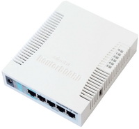
The choice fell on routers RB / 751G-2HnD.
Their characteristics:
- RAM: 64MB DDR SDRAM
- Processor: Atheros AR7241 400MHz CPU
- Hard Drive: 64MB onboard NAND storage chip
- Frequency: 2.4 GHz
- Ethernet: 5 independent 10/100/1000 ports
- USB: 1 port 2.0
- Power: via ethernet port 1 8-30V DC, through jack 8-30V DC (PSU included)
- Sensitivity: 802.11g: -96dBm @ 6Mbit / s to -81dBm @ 54Mbit / s, 802.11n: –96 dBm @ MCS0 to –78 dBm @ MCS7
- Power amplification: 802.11g: 30dBm @ 6Mbps to 27dBm @ 54 Mbps, 802.11n: 30dBm @ MCS0 to 26dBm @ MCS7
- power of the built-in radio module: 1W
- built-in antenna gain: 2.5dBi
- Power consumption: up to 7W
- OS: RouterOS, Level 4
I will not describe in detail where to find the winbox, what it is and how to use it. This information is very much in the vast network. Therefore, I will describe thesis, but with explanations.
At the time of this writing, software version 5.24. Downloading it here download2.mikrotik.com/routeros/5.24/routeros-mipsbe-5.24.npk is thrown into the Files and reloading the router. On the second we do the same.
So, we define for ourselves that R1 is the router where the cable from our provider comes, and R2 is a Wi-Fi receiver for an IPTV set-top box. The default device configuration offers us a DHCP client on the eth-1 port, and the eth2-eth5 ports are combined into a switch, plus a bridge to eth2 for wi-fi (wlan2) with a dhcp server in the 192.168.88.0/24 range.
')
So, setting up the router R1
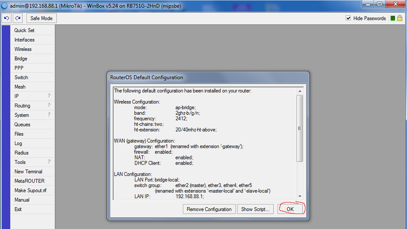
We connect the biline cable to eth1 to the R1 router and the computer to eth2 and run winbox. We connect to 192.168.88.1 with the admin username and an empty password. In the RouterOS Default Configuration window, click OK.
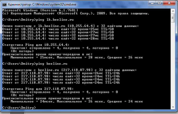
Since RouterOS does not know how to use dns-names in the Connect-to fields, first, by inserting the Beeline cable into the computer, we define the address tp.internet.beeline.ru. In my case, it turned out to be 10.255.255.239
(You can find scripts in the network that will determine the current address of the brasys tp.internet.beeline.ru and substitute them in the Connect-to field. As the provider uses round-robin dns to determine the less loaded bras)
Next, configure two NAT rules. One for the local network, the other for the Internet.
Go to IP-Firewall-NAT, delete the default configuration configuration, and create our own.
We check both rules:
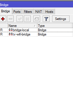
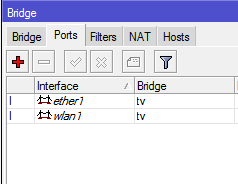
The next step is to remove the wlan1 membership in the bridge with ether2 and enable it in the bridge to ether1. To do this, open the Bridge, create a new bridge with the name, for example, tv-wifi-bridge, and on the Ports tab, add the wlan1 and ether1-gateway interfaces to it.
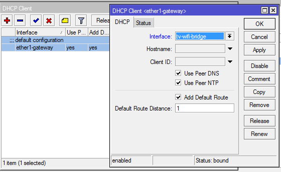
Since Iptv prefix also receives its address from the dhcp provider, then we need to change the dhcp-client interface. If you remember, it is assigned only to ether1. Reassign it to the Bridge tv-wifi-bridge.
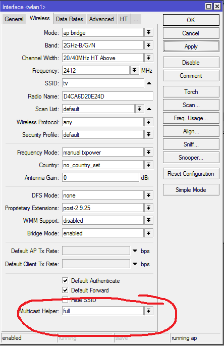
Now it's time to set up the wireless part of our project. First of all, we will prepare an access point for iptv console. There is nothing unusual, typical setting, except for the most important point. This is Multicast Helper. It must be in the full position.
Encryption is customized to your taste through Security Profiles, I will not dwell on this.
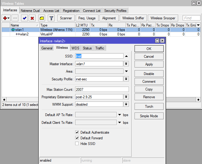
Now we are creating a virtual access point through which all of our other hardware will get on the Internet (phones, tablets, laptops, etc.). But first add one more security-profile, so as not to get confused.

Well, VirtualAP itself
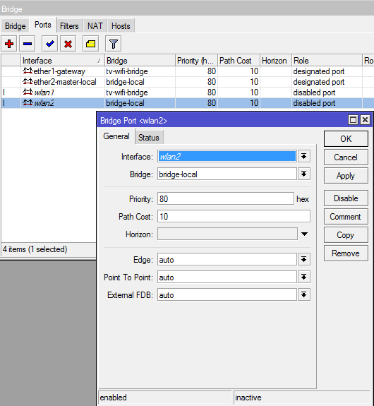
And add the resulting wlan2 to the bridge to ether2
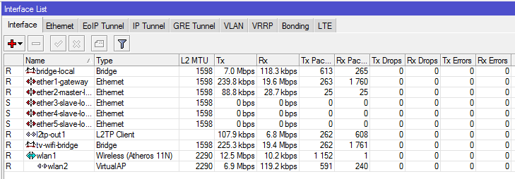
This completes the configuration of the R1 router. Wired devices go to the Internet through ports 2-5, wireless through a wlan2 access point with SSID “Inet”
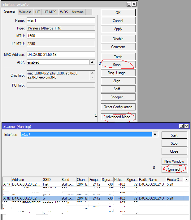
R2 router setup
Setting up this router is generally banal. Since Having the default configuration, we only need to perform an ether scan, find the point with the ssid “tv” and click the Connect button. If you use encryption, then make the appropriate amendments to the Security profiles. After that, you need to remove ether2 from the bridge, and add ehter1 instead. Caution! After that, you lose the connection with the router and the winbox closes.
We include the prefix in the eth1 port and everything is ready.
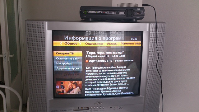
Here we see the recording channel 1HD and simultaneous downloading of the file. However, according to this scheme, I failed to squeeze more than 7-8 megabits from VirtualAP.
The CPU load of the router used as an access point for such a picture did not exceed 34-37%. The switching speed of the channels per eye does not differ from the cable connection.
During the experiments I tried to start up through IGMP - proxy. It seems to work, but the HD channels are freezing, entering pin codes does not work, recording does not work.
The method was also tried when the physical AP was used for the Internet, and VirtualAP for television. In this case, the transfer rate was no more than 1Mbps, which is naturally unacceptably low for watching TV. Instead of the video series, there were stills, replacing each other every 30 seconds.
On this experiment I consider successful and finished. There is a wide scope for further tuning. Ready to answer all questions. Thanks for attention.
What to do?
The following tasks emerge:
1) Release all client devices (laptops, computers, tablets, etc.) to the Internet via Wi-Fi
2) Put a set-top box leased from Beeline IPTV on the kitchen TV and make it work, while retaining all the functionality.
Well, if the first point does not cause difficulties, then the second makes you wonder.
Since I am an adherent and a long-time user of Mikrotik products, it was decided to solve the problem that arose on the equipment of this vendor. In addition, the existing certificate MTCNA gave strength and convinced that "the devil is not so bad as he is painted."
So, I recall the principle of connecting Beeline subscribers to the Internet.
The client equipment receives from the DHCP server a “gray” address from the subnet 10.0.0.0/8, which gives access to local resources, L2TP-BRASs, and, in fact, the IP IP multicast is also haunting. To get access directly to the Internet itself, you need to log in via the L2TP connection at tp.internet.beeline.ru. This scheme in the terminology of some manufacturers of home routers is called Russian Dual Access.
The choice fell on routers RB / 751G-2HnD.
Their characteristics:
- RAM: 64MB DDR SDRAM
- Processor: Atheros AR7241 400MHz CPU
- Hard Drive: 64MB onboard NAND storage chip
- Frequency: 2.4 GHz
- Ethernet: 5 independent 10/100/1000 ports
- USB: 1 port 2.0
- Power: via ethernet port 1 8-30V DC, through jack 8-30V DC (PSU included)
- Sensitivity: 802.11g: -96dBm @ 6Mbit / s to -81dBm @ 54Mbit / s, 802.11n: –96 dBm @ MCS0 to –78 dBm @ MCS7
- Power amplification: 802.11g: 30dBm @ 6Mbps to 27dBm @ 54 Mbps, 802.11n: 30dBm @ MCS0 to 26dBm @ MCS7
- power of the built-in radio module: 1W
- built-in antenna gain: 2.5dBi
- Power consumption: up to 7W
- OS: RouterOS, Level 4
I will not describe in detail where to find the winbox, what it is and how to use it. This information is very much in the vast network. Therefore, I will describe thesis, but with explanations.
At the time of this writing, software version 5.24. Downloading it here download2.mikrotik.com/routeros/5.24/routeros-mipsbe-5.24.npk is thrown into the Files and reloading the router. On the second we do the same.
So, we define for ourselves that R1 is the router where the cable from our provider comes, and R2 is a Wi-Fi receiver for an IPTV set-top box. The default device configuration offers us a DHCP client on the eth-1 port, and the eth2-eth5 ports are combined into a switch, plus a bridge to eth2 for wi-fi (wlan2) with a dhcp server in the 192.168.88.0/24 range.
')
So, setting up the router R1
We connect the biline cable to eth1 to the R1 router and the computer to eth2 and run winbox. We connect to 192.168.88.1 with the admin username and an empty password. In the RouterOS Default Configuration window, click OK.
Since RouterOS does not know how to use dns-names in the Connect-to fields, first, by inserting the Beeline cable into the computer, we define the address tp.internet.beeline.ru. In my case, it turned out to be 10.255.255.239
/interface l2tp-client add add-default-route=yes allow=pap,chap,mschap1,mschap2 connect-to=\ 10.255.255.239 dial-on-demand=no disabled=no max-mru=1460 max-mtu=1460 \ mrru=disabled name=l2tp-out1 password=password profile=\ default-encryption user=login (You can find scripts in the network that will determine the current address of the brasys tp.internet.beeline.ru and substitute them in the Connect-to field. As the provider uses round-robin dns to determine the less loaded bras)
Next, configure two NAT rules. One for the local network, the other for the Internet.
Go to IP-Firewall-NAT, delete the default configuration configuration, and create our own.
/ip firewall nat add action=masquerade chain=srcnat disabled=no dst-address=10.0.0.0/8 \ out-interface=ether1-gateway add action=masquerade chain=srcnat disabled=no dst-address=!10.0.0.0/8 \ out-interface=l2tp-out1 We check both rules:
The next step is to remove the wlan1 membership in the bridge with ether2 and enable it in the bridge to ether1. To do this, open the Bridge, create a new bridge with the name, for example, tv-wifi-bridge, and on the Ports tab, add the wlan1 and ether1-gateway interfaces to it.
/interface bridge add admin-mac=D4:CA:6D:20:E2:49 ageing-time=5m arp=enabled auto-mac=no \ disabled=no forward-delay=15s l2mtu=1598 max-message-age=20s mtu=1500 name=\ bridge-local priority=0x8000 protocol-mode=rstp transmit-hold-count=6 add admin-mac=00:00:00:00:00:00 ageing-time=5m arp=enabled auto-mac=yes \ disabled=no forward-delay=15s l2mtu=1598 max-message-age=20s mtu=1500 name=\ tv-wifi-bridge priority=0x8000 protocol-mode=none transmit-hold-count=6 /interface bridge port add bridge=bridge-local disabled=no edge=auto external-fdb=auto horizon=none \ interface=ether2-master-local path-cost=10 point-to-point=auto priority=\ 0x80 add bridge=tv-wifi-bridge disabled=no edge=auto external-fdb=auto horizon=none \ interface=wlan1 path-cost=10 point-to-point=auto priority=0x80 add bridge=tv-wifi-bridge disabled=no edge=auto external-fdb=auto horizon=none \ interface=ether1-gateway path-cost=10 point-to-point=auto priority=0x80 Since Iptv prefix also receives its address from the dhcp provider, then we need to change the dhcp-client interface. If you remember, it is assigned only to ether1. Reassign it to the Bridge tv-wifi-bridge.
/ip dhcp-client add add-default-route=yes comment="default configuration" \ default-route-distance=1 disabled=no interface=tv-wifi- use-peer-dns=yes use-peer-ntp=yes Now it's time to set up the wireless part of our project. First of all, we will prepare an access point for iptv console. There is nothing unusual, typical setting, except for the most important point. This is Multicast Helper. It must be in the full position.
/interface wireless set 0 adaptive-noise-immunity=none allow-sharedkey=no antenna-gain=0 antenna-mode=\ ant-a area="" arp=enabled band=2ghz-b/g/n basic-rates-a/g=6Mbps basic-rates-b=\ 1Mbps bridge-mode=enabled channel-width=20/40mhz-ht-above compression=no \ country=no_country_set default-ap-tx-limit=0 default-authentication=yes \ default-client-tx-limit=0 default-forwarding=yes dfs-mode=none \ disable-running-check=no disabled=no disconnect-timeout=3s distance=indoors \ frame-lifetime=0 frequency=2412 frequency-mode=manual-txpower frequency-offset=0 \ hide-ssid=no ht-ampdu-priorities=0 ht-amsdu-limit=8192 ht-amsdu-threshold=8192 \ ht-basic-mcs=mcs-0,mcs-1,mcs-2,mcs-3,mcs-4,mcs-5,mcs-6,mcs-7 ht-guard-interval=\ any ht-rxchains=0,1 ht-supported-mcs="mcs-0,mcs-1,mcs-2,mcs-3,mcs-4,mcs-5,mcs-6,m\ cs-7,mcs-8,mcs-9,mcs-10,mcs-11,mcs-12,mcs-13,mcs-14,mcs-15,mcs-16,mcs-17,mcs-18,m\ cs-19,mcs-20,mcs-21,mcs-22,mcs-23" ht-txchains=0,1 hw-fragmentation-threshold=\ disabled hw-protection-mode=none hw-protection-threshold=0 hw-retries=7 l2mtu=\ 2290 mac-address=D4:CA:6D:20:E2:4D max-station-count=2007 mode=ap-bridge mtu=\ 1500 multicast-helper=full name=wlan1 noise-floor-threshold=default \ nv2-cell-radius=30 nv2-noise-floor-offset=default nv2-preshared-key="" nv2-qos=\ default nv2-queue-count=2 nv2-security=disabled on-fail-retry-time=100ms \ periodic-calibration=default periodic-calibration-interval=60 preamble-mode=both \ proprietary-extensions=post-2.9.25 radio-name=D4CA6D20E24D rate-selection=\ advanced rate-set=default scan-list=default security-profile=default ssid=tv \ station-bridge-clone-mac=00:00:00:00:00:00 supported-rates-a/g=\ 6Mbps,9Mbps,12Mbps,18Mbps,24Mbps,36Mbps,48Mbps,54Mbps supported-rates-b=\ 1Mbps,2Mbps,5.5Mbps,11Mbps tdma-period-size=2 tx-power-mode=default \ update-stats-interval=disabled wds-cost-range=50-150 wds-default-bridge=none \ wds-default-cost=100 wds-ignore-ssid=no wds-mode=disabled wireless-protocol=any \ wmm-support=disabled Encryption is customized to your taste through Security Profiles, I will not dwell on this.
Now we are creating a virtual access point through which all of our other hardware will get on the Internet (phones, tablets, laptops, etc.). But first add one more security-profile, so as not to get confused.
/interface wireless security-profiles add authentication-types=wpa2-psk eap-methods="" group-ciphers=aes-ccm \ group-key-update=5m interim-update=0s management-protection=allowed \ management-protection-key="" mode=dynamic-keys name=inet-sec \ radius-eap-accounting=no radius-mac-accounting=no \ radius-mac-authentication=no radius-mac-caching=disabled \ radius-mac-format=XX:XX:XX:XX:XX:XX radius-mac-mode=as-username \ static-algo-0=none static-algo-1=none static-algo-2=none static-algo-3=\ none static-key-0="" static-key-1="" static-key-2="" static-key-3="" \ static-sta-private-algo=none static-sta-private-key="" \ static-transmit-key=key-0 supplicant-identity="" tls-certificate=none \ tls-mode=no-certificates unicast-ciphers=aes-ccm wpa-pre-shared-key="" \ wpa2-pre-shared-key=blablabla Well, VirtualAP itself
/interface wireless add area="" arp=enabled bridge-mode=enabled default-ap-tx-limit=0 \ default-authentication=yes default-client-tx-limit=0 default-forwarding=yes \ disable-running-check=no disabled=no hide-ssid=no l2mtu=2290 mac-address=\ D6:CA:6D:20:E2:4D master-interface=wlan1 max-station-count=2007 mtu=1500 \ multicast-helper=default name=wlan2 proprietary-extensions=post-2.9.25 \ security-profile=inet-sec ssid=Inet update-stats-interval=disabled \ wds-cost-range=0 wds-default-bridge=none wds-default-cost=0 wds-ignore-ssid=no \ wds-mode=disabled wmm-support=disabled And add the resulting wlan2 to the bridge to ether2
/interface bridge add bridge=bridge-local disabled=no edge=auto external-fdb=auto horizon=none \ interface=wlan2 path-cost=10 point-to-point=auto priority=0x80 This completes the configuration of the R1 router. Wired devices go to the Internet through ports 2-5, wireless through a wlan2 access point with SSID “Inet”
R2 router setup
Setting up this router is generally banal. Since Having the default configuration, we only need to perform an ether scan, find the point with the ssid “tv” and click the Connect button. If you use encryption, then make the appropriate amendments to the Security profiles. After that, you need to remove ether2 from the bridge, and add ehter1 instead. Caution! After that, you lose the connection with the router and the winbox closes.
We include the prefix in the eth1 port and everything is ready.
Here we see the recording channel 1HD and simultaneous downloading of the file. However, according to this scheme, I failed to squeeze more than 7-8 megabits from VirtualAP.
The CPU load of the router used as an access point for such a picture did not exceed 34-37%. The switching speed of the channels per eye does not differ from the cable connection.
During the experiments I tried to start up through IGMP - proxy. It seems to work, but the HD channels are freezing, entering pin codes does not work, recording does not work.
The method was also tried when the physical AP was used for the Internet, and VirtualAP for television. In this case, the transfer rate was no more than 1Mbps, which is naturally unacceptably low for watching TV. Instead of the video series, there were stills, replacing each other every 30 seconds.
On this experiment I consider successful and finished. There is a wide scope for further tuning. Ready to answer all questions. Thanks for attention.
Source: https://habr.com/ru/post/174111/
All Articles