A bit of "organic" * in the five-inch compartment
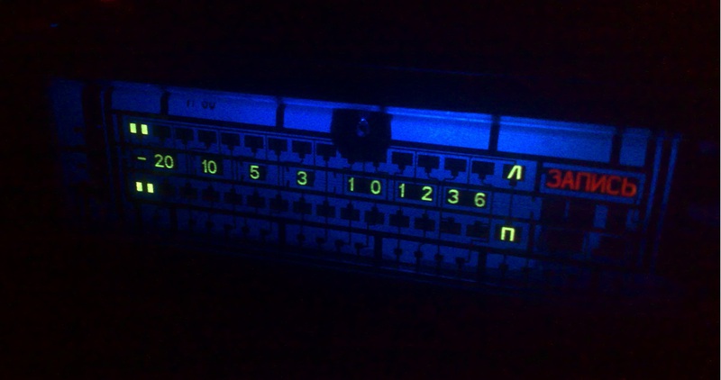
Observing the flow of articles devoted to watches with vacuum indicators, I decided to share my “invention” with you. But it's not about the clock. It will be a question of the vacuum luminescent indicator of type ILT6-30M. And a device that does not perform any serious tasks (for now), but is simply a decorative element, such as a "mood lamp."
* warm, soft, lively, lamp ... - well, organic!
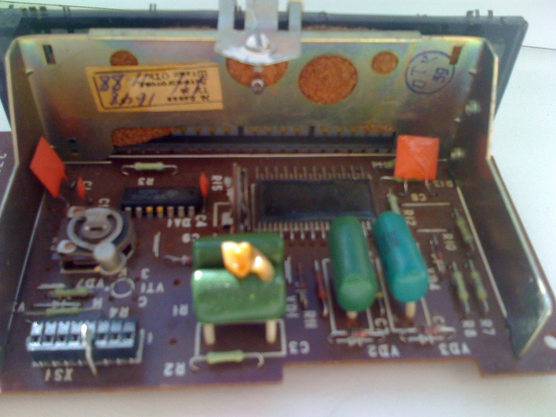
I got this indicator along with the board on which it was installed. The whole structure was a complete device for indicating the level of the recording / playback signal used in audio equipment of the 80s. Having twisted this “thing” in my hands, I felt sorry for disassembling it, especially since there was nothing to stock up on from it. And it was decided to revive her. After the indicator blinked cheerfully with two stripes, an indescribably mysterious green color, the search began - “where to shove it”. But it never crossed my mind. Everywhere he seemed odd or just stupid. So he was lying on the shelf until the ACER CD, which was lame in the eye, sat next to him. So the idea arose of “cramming” it into a standard case from a CD-ROM, and at the same time, decorate the “boring box” under the table.

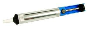
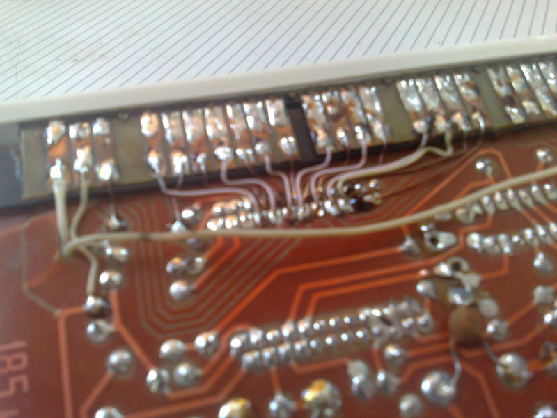
This fluorescent indicator has a size of 126x39 mm, and the landing one is even bigger! And experts of the genre have already had suspicions ... - no, no ... I squeezed him in there. But for this it was necessary to tinker. The first step is to drop the indicator lamp out of the board. This should be done very carefully and effortlessly, otherwise you can ruin the board and break the indicator's conclusions. I used for this purpose a vacuum syringe for suction of tin.
Further, all conclusions should be straightened and done very accurately and accurately! None - "slightly crooked." Further, the conclusions must be bent, strictly in the place of their appearance from the glass of the flask. The denser the output is pressed to the glass of the flask, the better. Take this operation very deliberately! Bend and bend will not work (well, if only once).
')
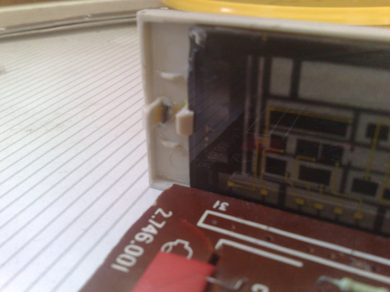
Metal mounting band from the board must be removed altogether. But the indicator will not hold on the word of honor, the front (front) panel of the device will be the support and support for it. To do this, on it on the back of the latch are glued, which will be fixed indicator lamp. And the front panel itself, in turn, with a pair of other latches, will be attached to the metal case. A little inconvenient construction for the assembly ... - well, how it happened.
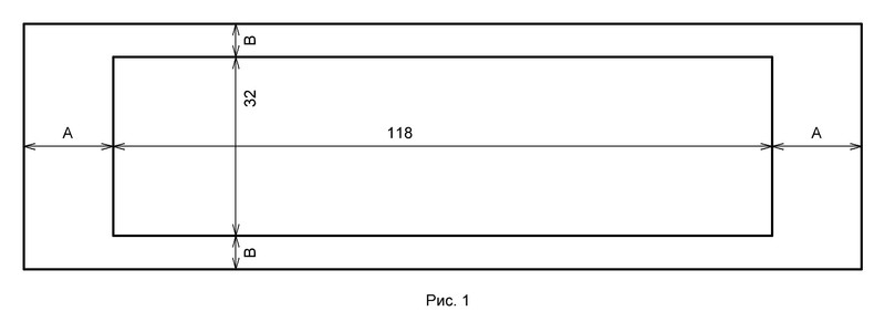
I made the front (front) panel of the standard plug of the five-inch compartment. The markup is shown in fig. one.
Now, the indicator and the board need to be connected again. To do this, I used a small strip of one-sided PCB, which also plays a role as a kind of distancer. This is required when installing the board in the case. On the strip board, it is necessary, in some way (to etch, cut), to make contact pads. Strip-strip must be glued to the main board.
The inner surfaces of the metal body must be glued over with an insulating material. The contacts of the indicator lamp will rest against the bottom panel of the housing. All but, but fits.
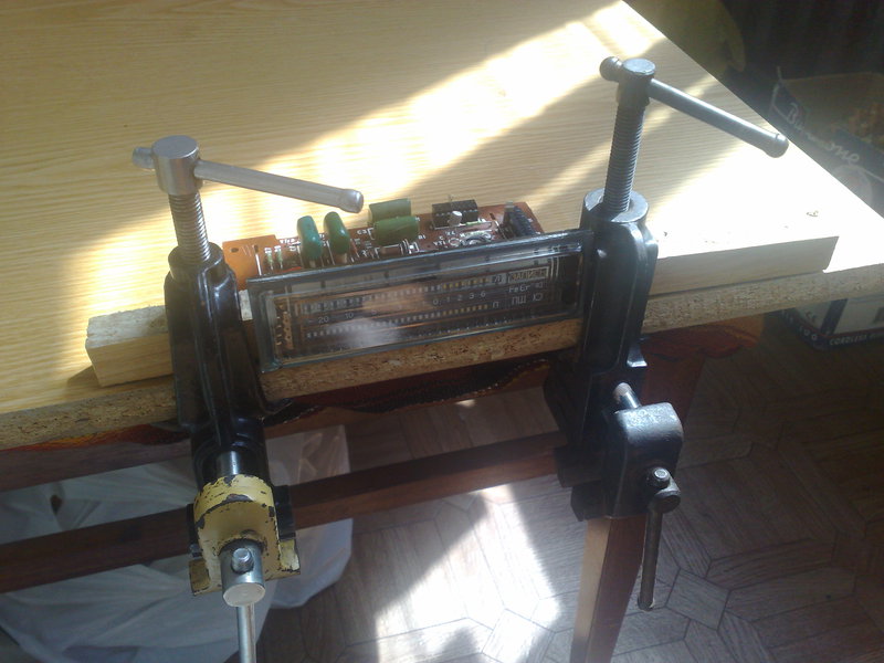
When everything is ready, you can start the assembly.
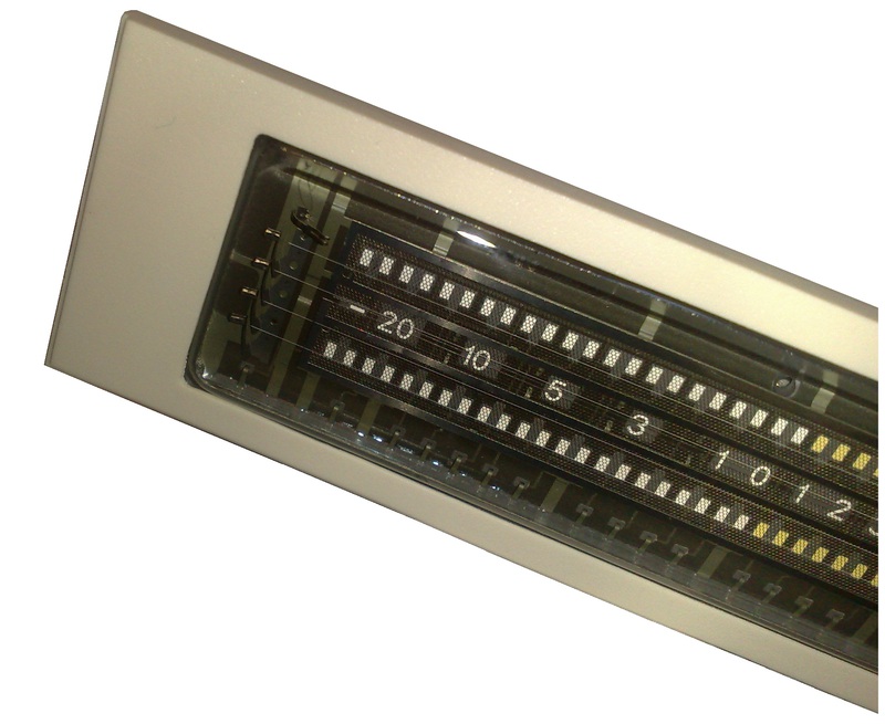
The indicator is set deliberately bulging, with all its smooth bends. And, of course, not hiding under the tinted glass. All internal elements - grids, cathode filaments, anodes, should be accessible for viewing (well, it was not I who invented ... such a genre).
Electronic lamps, devices, mysterious and "voracious." They feed abundantly and varied. Thus, the display module, built on an indicator lamp ILT6-30M, requires as many as five different power poles! Two poles of alternating voltage supply 4.25 Volts, power poles +13.9 and -13.9 and another mysterious power supply +38 Volts. Therefore, the following rather boring part of the story is devoted to the power supply.
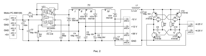
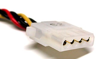
The power supply is based on the integrated driver DC / DC converters - MC34063. The scheme is shown in Fig. 2. With the appointment, I think everything is clear - to convert a certain amount of energy into the sum of some other energies needed to supply the circuit. This amount was determined empirically, consumption currents were measured through the feed channels. From an alternating voltage source of 4.25 volts, necessary for the filaments of the indicator lamp, the current was 100 mA . From the pole +12 Volt, the current consumption was 12 mA , and from -12 Volt 10 mA . The current consumption on the +38 Volt channel is quite “penny” - 3 mA . Add it all in the form of power, it turned out 0,803 watts. Considering the fact that the main consumer is the filament, which is powered by an alternating voltage source of 4.25 Volt, these two values form the basis for calculating the power supply - 4.25V / 1W. All other voltages were supposed to be obtained in "roundabout" ways. During the first test runs of the collider ... oh! - indicator, was revealed one nuance associated with the power of the filament of the indicator lamp. It turned out that the constant voltage, it "digests" very badly. This is due to the deep physics of the processes occurring inside the lamp, and I think it’s not worth delving into them. This is expressed in the uneven brightness of the anodes of the indicator. From the side of the positive potential connection, they shine brighter. And from the side of the opposite potential, zero, they do not shine at all. After this “discovery”, the circuit was supplemented with a key DC / AC inverter on transistors. As a result, I got a circuit (see Fig. 2), which makes it possible to power our device from one power pole. I chose 12 volts. Power is supplied to the device through the standard Molex PC-8981 computer power connector.
The most important part of the power supply is the choke. In our design, it is also an autotransformer, and just a transformer ... - a solid "chemistry". For my option, I chose the B22 2000NM core, or rather “did not choose”, but I just had one. A non-magnetic gap must be made in the core. This is done in order to avoid saturation of the core, it is also good for accumulating magnetic induction energy in the core.
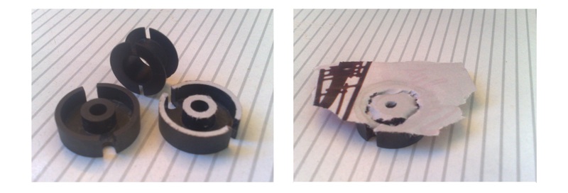
The easiest way to make a gap is to stick one cup of the core to a thin piece of paper. After the glue dries, the excess must be carefully cut with a scalpel. All windings dangle on the spool, which is then embedded in the core cups. Slots are provided for the leads of the windings in the cups. The most important winding of this “choke transformer” is primary, indicated in the diagram by the numeral I. This winding is the only one that was honestly calculated using datasheet formulas; all other windings were from proportional ratios. Winding I contains 24 turns of wire with a diameter of 0.3 mm , the initial inductance of 250 uH (microgenry). Winding II and IV , 47 and 73 turns, respectively, wire diameter 0.2 mm . Winding III -143 turns, wires with a diameter of 0.1 mm .
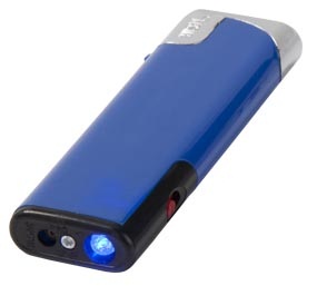
In order to further exacerbate the effect of mystery and manifest the internal technological details of the indicator lamp, I used a backlight. The backlight is blue, and this is not special, just at my disposal there were two empty lighters with a “flashlight”. And they lost their "flashlights". I note that the white light looks no less impressive, but the white LED I felt sorry for.
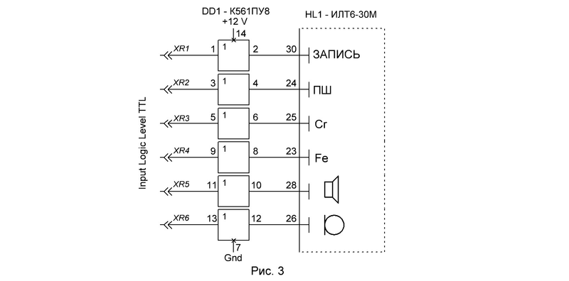
Given the fact that the device clearly marks in the category of "netenok", I stock all the possible functionality for the future. In addition to the two scale bars, six more mnemonic symbols can be displayed on the indicator. Their control is reserved as inputs for TTL logic levels. To match the logic levels of TTL and the levels of the anode voltage of the segments, the K561PU8 chip was used (Fig. 3).
At the moment, the indicator is connected to the output of the sound card of the computer through a buffer amplifier and simply “twitches” in the music. Although the functions of the measuring device, which he was before the barbaric rework, he did not lose. And if anyone needs to know the signal level in dBu, then it is quite suitable for this task.
In the future, there is a desire to puzzle this "blinker" more sensibly. For example, make show the speed of distribution / download in the torrent. A very attractive project on this topic can be found here .
And finally, a video of the device.
And one more
* warm, soft, lively, lamp ... - well, organic!
I got this indicator along with the board on which it was installed. The whole structure was a complete device for indicating the level of the recording / playback signal used in audio equipment of the 80s. Having twisted this “thing” in my hands, I felt sorry for disassembling it, especially since there was nothing to stock up on from it. And it was decided to revive her. After the indicator blinked cheerfully with two stripes, an indescribably mysterious green color, the search began - “where to shove it”. But it never crossed my mind. Everywhere he seemed odd or just stupid. So he was lying on the shelf until the ACER CD, which was lame in the eye, sat next to him. So the idea arose of “cramming” it into a standard case from a CD-ROM, and at the same time, decorate the “boring box” under the table.
This fluorescent indicator has a size of 126x39 mm, and the landing one is even bigger! And experts of the genre have already had suspicions ... - no, no ... I squeezed him in there. But for this it was necessary to tinker. The first step is to drop the indicator lamp out of the board. This should be done very carefully and effortlessly, otherwise you can ruin the board and break the indicator's conclusions. I used for this purpose a vacuum syringe for suction of tin.
Further, all conclusions should be straightened and done very accurately and accurately! None - "slightly crooked." Further, the conclusions must be bent, strictly in the place of their appearance from the glass of the flask. The denser the output is pressed to the glass of the flask, the better. Take this operation very deliberately! Bend and bend will not work (well, if only once).
')
Metal mounting band from the board must be removed altogether. But the indicator will not hold on the word of honor, the front (front) panel of the device will be the support and support for it. To do this, on it on the back of the latch are glued, which will be fixed indicator lamp. And the front panel itself, in turn, with a pair of other latches, will be attached to the metal case. A little inconvenient construction for the assembly ... - well, how it happened.
I made the front (front) panel of the standard plug of the five-inch compartment. The markup is shown in fig. one.
Now, the indicator and the board need to be connected again. To do this, I used a small strip of one-sided PCB, which also plays a role as a kind of distancer. This is required when installing the board in the case. On the strip board, it is necessary, in some way (to etch, cut), to make contact pads. Strip-strip must be glued to the main board.
The inner surfaces of the metal body must be glued over with an insulating material. The contacts of the indicator lamp will rest against the bottom panel of the housing. All but, but fits.
When everything is ready, you can start the assembly.
The indicator is set deliberately bulging, with all its smooth bends. And, of course, not hiding under the tinted glass. All internal elements - grids, cathode filaments, anodes, should be accessible for viewing (well, it was not I who invented ... such a genre).
Electronic lamps, devices, mysterious and "voracious." They feed abundantly and varied. Thus, the display module, built on an indicator lamp ILT6-30M, requires as many as five different power poles! Two poles of alternating voltage supply 4.25 Volts, power poles +13.9 and -13.9 and another mysterious power supply +38 Volts. Therefore, the following rather boring part of the story is devoted to the power supply.
The power supply is based on the integrated driver DC / DC converters - MC34063. The scheme is shown in Fig. 2. With the appointment, I think everything is clear - to convert a certain amount of energy into the sum of some other energies needed to supply the circuit. This amount was determined empirically, consumption currents were measured through the feed channels. From an alternating voltage source of 4.25 volts, necessary for the filaments of the indicator lamp, the current was 100 mA . From the pole +12 Volt, the current consumption was 12 mA , and from -12 Volt 10 mA . The current consumption on the +38 Volt channel is quite “penny” - 3 mA . Add it all in the form of power, it turned out 0,803 watts. Considering the fact that the main consumer is the filament, which is powered by an alternating voltage source of 4.25 Volt, these two values form the basis for calculating the power supply - 4.25V / 1W. All other voltages were supposed to be obtained in "roundabout" ways. During the first test runs of the collider ... oh! - indicator, was revealed one nuance associated with the power of the filament of the indicator lamp. It turned out that the constant voltage, it "digests" very badly. This is due to the deep physics of the processes occurring inside the lamp, and I think it’s not worth delving into them. This is expressed in the uneven brightness of the anodes of the indicator. From the side of the positive potential connection, they shine brighter. And from the side of the opposite potential, zero, they do not shine at all. After this “discovery”, the circuit was supplemented with a key DC / AC inverter on transistors. As a result, I got a circuit (see Fig. 2), which makes it possible to power our device from one power pole. I chose 12 volts. Power is supplied to the device through the standard Molex PC-8981 computer power connector.
The most important part of the power supply is the choke. In our design, it is also an autotransformer, and just a transformer ... - a solid "chemistry". For my option, I chose the B22 2000NM core, or rather “did not choose”, but I just had one. A non-magnetic gap must be made in the core. This is done in order to avoid saturation of the core, it is also good for accumulating magnetic induction energy in the core.
The easiest way to make a gap is to stick one cup of the core to a thin piece of paper. After the glue dries, the excess must be carefully cut with a scalpel. All windings dangle on the spool, which is then embedded in the core cups. Slots are provided for the leads of the windings in the cups. The most important winding of this “choke transformer” is primary, indicated in the diagram by the numeral I. This winding is the only one that was honestly calculated using datasheet formulas; all other windings were from proportional ratios. Winding I contains 24 turns of wire with a diameter of 0.3 mm , the initial inductance of 250 uH (microgenry). Winding II and IV , 47 and 73 turns, respectively, wire diameter 0.2 mm . Winding III -143 turns, wires with a diameter of 0.1 mm .
In order to further exacerbate the effect of mystery and manifest the internal technological details of the indicator lamp, I used a backlight. The backlight is blue, and this is not special, just at my disposal there were two empty lighters with a “flashlight”. And they lost their "flashlights". I note that the white light looks no less impressive, but the white LED I felt sorry for.
Given the fact that the device clearly marks in the category of "netenok", I stock all the possible functionality for the future. In addition to the two scale bars, six more mnemonic symbols can be displayed on the indicator. Their control is reserved as inputs for TTL logic levels. To match the logic levels of TTL and the levels of the anode voltage of the segments, the K561PU8 chip was used (Fig. 3).
At the moment, the indicator is connected to the output of the sound card of the computer through a buffer amplifier and simply “twitches” in the music. Although the functions of the measuring device, which he was before the barbaric rework, he did not lose. And if anyone needs to know the signal level in dBu, then it is quite suitable for this task.
In the future, there is a desire to puzzle this "blinker" more sensibly. For example, make show the speed of distribution / download in the torrent. A very attractive project on this topic can be found here .
 | ATTENTION! The device has a pronounced hypnotic effect. Not recommended for long-term demonstration easily inspired by people. Demonstration to people who have not seen anything other than an LCD display with a touchscreen should be made with an introductory instruction: that it is not dangerous, that it is not from space and that it is not related to "green men." |
And finally, a video of the device.
And one more
Source: https://habr.com/ru/post/173777/
All Articles