Writing a Rubik's Cube Emulator
OpenGL is a platform-independent specification that describes a software interface for creating computer applications using two-dimensional and three-dimensional graphics.
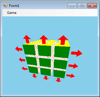
In this article I will describe how you can create a Rubik's Cube emulator on OpenGL.
The cube will be in 3D and can be rotated with the mouse, and you can turn the faces by clicking the arrows on the arrows. At the same time, arrows appear at the face closest to the viewer.
')
I will describe the creation of the Rubik's Cube emulator in the C # language, for OpenGL I will use the OpenTK library. It is necessary to download it, and make a link to this library in Visual Studio.
Now a short description about 3D. Objects in 3D have 3 x, y, z coordinates, and on the monitor screen only two coordinates. Obviously, the projection should be shown on the monitor screen.
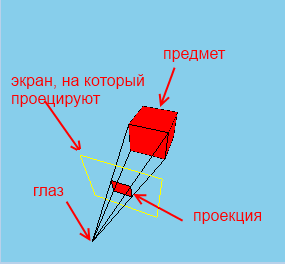
But we don’t have to project rear objects or which stand to the side. Also, we should not project ideas that are too far away. (Remember, as in racing, distant objects appear when you start to approach them).
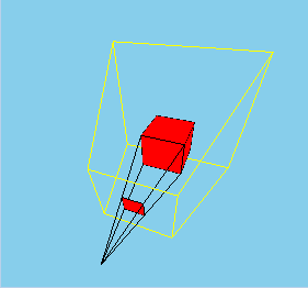
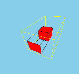
Therefore, we must limit what we can see:

Such a truncated pyramid called FrustRum (FrustRum), to show the object on the screen, we determine whether it fits in Frustrum (those parts that do not fit we cut off), then we project on the screen. OpenGL does all this for us.
Download the OpenTK library . Run the file, unpack the library.
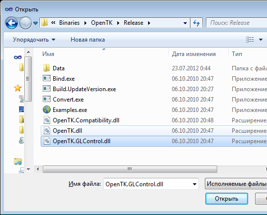
Create a project, add a link to the file OpenTK.dll. And since, we will use the GLControl control, on which the Rubik's Cube will be displayed, we also add a link to OpenTK.GLControl.dll
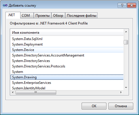
OpenTK also requires a link to System.Drawing.dll, so once again we enter the interface for adding a link, and select the .Net tab and look for System.Drawing, and add it.
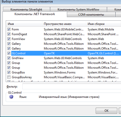
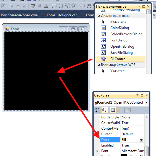
I will use OpenGL, inside a regular GUI program. Therefore, in the constructor mode, right-click on the toolbar, and select “Select elements”, go to the “.NET Framework Components” tab and select the OpenTK.GLControl.dll file. A new element GLControl will appear in the list, put a check mark in front of it. OK. A new GLControl item will appear on the toolbar. We transfer it to the form and stretch it to its entire shape.
The GLControl element has a Load event, it fires when this element has loaded.
(Click on it to fill the body of the handler, the glControl1_Load method will appear)
The creators of OpenTK do not recommend starting working with GLControl before it is loaded, so you need to set a variable that will store the value of whether GLControl was loaded:
glControl1_Load - the method that handles the Load event
glControl1_Paint - the method that handles the Paint event, works, for example, when we hide, and then open the window again, or, for example, resize the window.
Actually draw a cube.
using OpenTK; - needed for the Matrix4 class (4x4 matrix)
using OpenTK.Graphics.OpenGL; - needed to gain access to the GL object.
GL is an object through which to actually call OpenGL commands.
GL.ClearColor (Color.SkyBlue); - fills in blue
GL.Enable (EnableCap.DepthTest); - this line is needed to distant elements overlap neighbors.
Here we set the matrix, which is responsible for Frustum:
1) viewing angle of 80 degrees
2) the ratio of length to height - 1
3) the distance to the first face is 20
4) distance to the far edge - 500
Go to the projection mode, and set this matrix. About the modes will be discussed later.
Initialize ColorBufferBit and DepthBuffer
ColorBuffer. Color Buffer. Each pixel on the screen is associated with a color value, which is recorded in a color buffer. The call to GL.Clear (ClearBufferMask.ColorBufferBit) will flood the window with the SkyBlue color (see above).
DepthBuffer. He is a Z-Buffer. Depth buffer The fact is that two points in 3D space can be projected onto one point on the screen. It is necessary that the near point overlaps the furthest. To do this, calculate the “depth” of the point (the value is inversely proportional to the distance from the camera to the point) and record its value in the buffer (the peekel is such and such, the depth is such and such)
if the next point is projected on the same pixel, then it is necessary to compare the “depth” of the new point with the recorded Depth-buffer. If the new point is “less deep” (more closer to the camera), then its projection should overlap the existing one, otherwise leave everything as it is.
At the beginning of the cube drawing, we need to clear the Depth-Buffer.
Here we set our camera at the point (30, 70, 80), the direction of gaze to the center of the coordinate system (0, 0, 0). The orientation is such that the axis OY is directed upwards.
If we do
Then we will look at the cube at an angle, as if we tilted our head 45 degrees to the left.
Next, the cube itself is drawn: first, the faces are red, then black - the edges
Then the command is called.
The fact is that the default OpenGL in OpenTK is double-buffer: each buffer (ColorBuffer, DepthBuffer and others that I did not mention) is duplicated. When we draw an image, we use some buffers. And at this time on the screen displays an image that is received from other buffers.
The command glControl1.SwapBuffers (); we display the image using the buffers in which we painted it.
By the way, if you clear the color buffer only for the first time
That is, clear only one color buffer (in fact, fill it with blue color), and not clear the other. And then minimize / maximize the window. That background color will change from blue to black. (however, if you resize the window, it will always become black (apparently, both buffers are reset during resize).
Objects are defined in 3-dimensional coordinates. These coordinates are called object. Each object can be defined in its object coordinates. To build a world of different 3d objects that stand relative to each other in different positions,
you need to multiply the object coordinates of each object by the corresponding model matrix . Then we get the new coordinates of each object in the new common world space.
At the same time, we can look at the world of objects from different sides, we can flip the camera, we can move closer to the object and move away from it. Multiplying the coordinates of the objects (coordinates in world space) by the corresponding view transformation matrixes (view Matrix), we get the view coordinates of each object.
In OpenGL, the model transformation matrix (model Matrix) is combined with the view transformation matrix (view Matrix) into one (modelView Matrix). (After all, we can postpone the object in two ways: change its world coordinates (postpone the object itself), or move the camera away from it (get new view coordinates)).
Then the coordinates are multiplied by the projection matrix (projection Matrix), which either sets the Frustrum (perspective projection):
or sets the orthogonal projection:
Multiplying the view coordinates by the projection matrix, we get the truncated coordinates (clip coordinates). By dividing each coordinate (x, y, z) by 4 ω, we get the normalized device coordinates (Normalize Device Coordinates, NDC) each of which is from -1 to 1, with the Z axis already deployed from us (that is, Frustum turns into a cube and turns around 180 degrees from us),
then, the coordinates by shift and scaling are converted to window coordinates (window coordinates), which are finally involved in the construction of a 2D image on the screen.
To switch to the projection matrix control mode, we need to call the GL.MatrixMode function with the MatrixMode.Projection parameter:
GL.MatrixMode (MatrixMode.Projection);
And in order to switch to the matrix-model transformation mode, we need to call the GL.MatrixMode function with the MatrixMode.Modelvew parameter:
GL.MatrixMode (MatrixMode.ModelView);
Add a code to glControl1_Paint that draws the OX, OY, OZ axes:
Also in the form designer, you need to add an event handler for the KeyDown event, the glControl1_KeyDown function will appear. Fill it with the following code:
That is, when you press the A key on the keyboard, we switch to the projection mode and rotate around the OZ axis 30 degrees counterclockwise,
and when you press the B key, the rotation around the OZ axis is also performed, but already in the mode-model transformation mode.
I give the full code here:
If we press the letter A on the keyboard, then we will rotate the 2D image on the screen:

Thus, in perspective coordinates, the OZ axis is also the Frustrum axis.
If you press B on the keyboard, then we will rotate the coordinate system around the OZ axis:
Code
With the same success it was possible to replace this:
The same code above the ModelView matrix will give the same result.
Actually, let's move on to the description of the Rubik's cube emulator program, which you can download here: http: //trukoding.rf/files/opengl.zip
I will not describe everything, as there will be a lot of text. I will describe the key points.
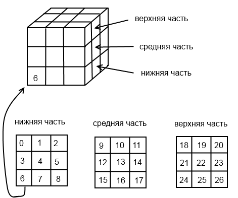
1) Rubik's Cube, the edge of which consists of 3 cubes consists of 27 small cubes.
In the process of rotating the faces of the Rubik's Cube (KR), small cubes will change their location. In the process of rotation of the face of the CD, you need to know which small cubes to rotate (after all, different cubes can appear on the face), also after the next rotation of the face of the CD, you need to check whether the cube is going to.
To track the positions of the cubes, I applied an array of positions:
int [] positions;
His keys are the numbers of the cubes, and the values of the position numbers.
By the way, I marked the position as follows:
2) When you rotate the face of the CD, the corresponding small cubes change not only the location, but turn other sides. When we turned the face one turn (90 degrees),
then the new state of the cube can be obtained in two ways:
1) turn the corresponding cubes around a certain axis by 90 degrees (which was done when turning)
2) either rearrange the cubes, to new places, and rotate each cube around its axis by 90 degrees.
The next class is used to describe a cube in space.
the fields X, Y, Z are the angles relative to the axes OX, OY, OZ
when we rotate any face, the corresponding angle of the corresponding cubes changes.
After completing the rotation, I reset these angles, move the cubes to new positions (that is, change the position array accordingly), and rotate the cubes around its axis (I will show what I mean by this). The user sees only the rotation itself.
The object of class angleXYZ is in each cube and is stored in the angles collection:
3) Each cube contains 8 corner points. Knowing these points, drawing a cube is not a problem.
The coordinates of the points are stored in the 3-dimensional array of edges. To transfer and rotate coordinates using only multiplication operations (and not addition and multiplication), I use 1x4 matrices for coordinates and 4x4 matrices for transfer matrices and multiplication.
The use of 4x4 matrices allows us to combine the multiplication operation together and the transfer matrix, and rotation. Thus, in one multiplication operation, two things can be done: the transfer and the multiplication.
To find out the displacement of the next small cube (of which the Rubik's Cube consists) relative to the zero position in the assembled CD, I wrote a special function getOffsets, which takes the number of the cube and returns how many cubes to retreat on each of the axes.
4) There is another dictionary intersect_planes.
Dictionary keys are axes (Axis enumeration object (public enum Axis {X, Y, Z};)),
and values are the faces on the corresponding axis, objects of my class Plane (plane).
The class Plane is needed to store the coordinates of the points of the corner points of each face.
the object of the class Plane simply stores the coordinates of the 3 points, and the constructor of this class checks that they are different. But it was possible and not to get a separate class, but just to manage a two-dimensional array:
but it strains to access the elements of the array through a series of square brackets.
This dictionary is needed in order to determine on the plane of which face we clicked the mouse, respectively, which part of the Rubik's Cube must be rotated. The definition of the plane, the arrows which clicked the mouse, will be written later.
5) An important object of my vp ViewPoint class.
which stores the value of the coordinates of the point of view of the Rubik's Cube, the fact is that when I rotate with the mouse of the Rubik's Cube, I actually change the position of the point of view, and the cube stands still.
The ViewPoint class is needed to get the closest axis to the viewpoint (getNearestAxis method). This is necessary to determine on which face to show the arrows, that is, which parts to rotate, when you click the mouse.
The point of view rotates around the Rubik's Cube on the sphere, so it is convenient to operate with an angle relative to the axis OX (angle α) and an angle relative to the oci OY (angle β):

At the vp object, the setter properties angle_view_alpha and angle_view_beta are opened, the angle α and angle β are changed through them, and the coordinates of the camera (viewpoints) are calculated in these body angles.
Also, this class has getter properties that can be used to determine if the camera is not upside down, from which side of a certain axis we are looking at a cube (for example, from positive X values, or from negative Z values).
This is necessary in order to correctly determine in which direction to turn the faces of the Rubik's Cube. The Rubik's Cube itself is located so that its center is at the center of the origin of coordinates.
I will describe only the key points, otherwise it will be very long. I already feel Lev Nikolayevich.
The Rubik's Cube itself I want to draw so that its center coincides with the center of the origin, therefore, going into the ModelView matrix mode, I do the translation of the coordinate system half the length of the Rubik's Cube along all axes:
Then, by the number of cubes (27 times), the cube function is called, which draws small cubes except that it is in the center of the CU, because it will never be seen.
I first save the current ModelView matrix in the stack that OpenGL provides:
and at the end I restore this matrix from the stack:
It is necessary that changing the ModelView matrix (turns, transfers) of one cube does not affect the matrices of other cubes. In other words, if we want to spin one small cube, then we should not spin others.
To animate the scrolling of a face, I turn around around any of the axes.
The code is written in such a way that only one of the angles angle.X, angle.Y, angle.Z at one moment can be non-zero, so here you can only rotate around one axis, or not at all.
But, bearing in mind that the coordinate system is shifted, you must first return it to its place, make a turn, and again make a reverse transfer, which is what I have done:

Next, the edges array is used to draw the cube, the colors of the cube faces are determined from the cube number, which is passed to the cube function.
The center of the coordinate system using GL.Translate returns to its original location.
vp ViewPoint . GL.Rotate GL.Translate , .
, , , , , .
2- (NDC, ), , ModelView .
, .
, , ( intersect_planes, ).
. ( ), . , , XOY, XOZ, YOZ ( / 4- ).
.
EasingTimer, System.Timers.Timer, Singleton, . , . run, , , .
duration EasingTimer .
:
edges, 8 , .
glControl1.Invalidate(); Render, cube, .
positions, (27 , 27 ). , , , “ 3 90 X”, “ , 3, 90 X”.
, angles, . , . X, Y , Y, X.
, cube,
, , : X, Y, Z.
, . edges , , , . edges .
. MouseDown, MouseMove, MouseUp. , , , .
vp ViewPoint, X, Y ( ), ViewPoint , ModelView:
3 ,
3 , .
3 ,
, Y , vp.orintation_y == 1, vp.orintation_y == -1
.
, , . Thanks for attention. : http://xn--c1abmgrdmpk4e.xn--p1ai/files/opengl.zip
In this article I will describe how you can create a Rubik's Cube emulator on OpenGL.
The cube will be in 3D and can be rotated with the mouse, and you can turn the faces by clicking the arrows on the arrows. At the same time, arrows appear at the face closest to the viewer.
')
I will describe the creation of the Rubik's Cube emulator in the C # language, for OpenGL I will use the OpenTK library. It is necessary to download it, and make a link to this library in Visual Studio.
3D tour
Now a short description about 3D. Objects in 3D have 3 x, y, z coordinates, and on the monitor screen only two coordinates. Obviously, the projection should be shown on the monitor screen.
But we don’t have to project rear objects or which stand to the side. Also, we should not project ideas that are too far away. (Remember, as in racing, distant objects appear when you start to approach them).
Therefore, we must limit what we can see:
Such a truncated pyramid called FrustRum (FrustRum), to show the object on the screen, we determine whether it fits in Frustrum (those parts that do not fit we cut off), then we project on the screen. OpenGL does all this for us.
Attempt at writing
Download the OpenTK library . Run the file, unpack the library.
Create a project, add a link to the file OpenTK.dll. And since, we will use the GLControl control, on which the Rubik's Cube will be displayed, we also add a link to OpenTK.GLControl.dll
OpenTK also requires a link to System.Drawing.dll, so once again we enter the interface for adding a link, and select the .Net tab and look for System.Drawing, and add it.
Add OpenTK Library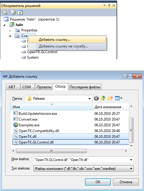
I will use OpenGL, inside a regular GUI program. Therefore, in the constructor mode, right-click on the toolbar, and select “Select elements”, go to the “.NET Framework Components” tab and select the OpenTK.GLControl.dll file. A new element GLControl will appear in the list, put a check mark in front of it. OK. A new GLControl item will appear on the toolbar. We transfer it to the form and stretch it to its entire shape.
Adding a GLControl control (canvas, canvas)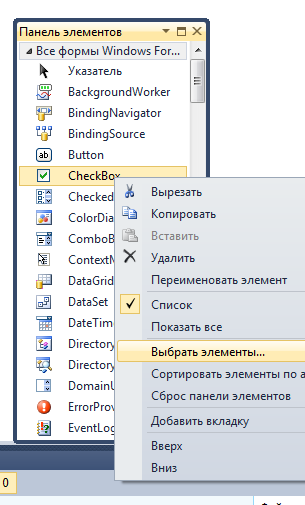
The GLControl element has a Load event, it fires when this element has loaded.
(Click on it to fill the body of the handler, the glControl1_Load method will appear)
The creators of OpenTK do not recommend starting working with GLControl before it is loaded, so you need to set a variable that will store the value of whether GLControl was loaded:
Code
using System; using System.Collections.Generic; using System.ComponentModel; using System.Data; using System.Drawing; using System.Linq; using System.Text; using System.Windows.Forms; using OpenTK; using OpenTK.Graphics.OpenGL; namespace habr { public partial class Form1 : Form { bool loaded = false;//<-------------------------------------- public Form1() { InitializeComponent(); } private void glControl1_Load(object sender, EventArgs e) { loaded = true;//<-------------------------------------- } private void glControl1_Paint(object sender, PaintEventArgs e) { if (!loaded)//<-------------------------------------- return;//<-------------------------------------- } } } glControl1_Load - the method that handles the Load event
glControl1_Paint - the method that handles the Paint event, works, for example, when we hide, and then open the window again, or, for example, resize the window.
Actually draw a cube.
Code that draws a small cube
using System; using System.Collections.Generic; using System.ComponentModel; using System.Data; using System.Drawing; using System.Linq; using System.Text; using System.Windows.Forms; using OpenTK; using OpenTK.Graphics.OpenGL; namespace habr { public partial class Form1 : Form { bool loaded = false; public Form1() { InitializeComponent(); } private void glControl1_Load(object sender, EventArgs e) { loaded = true; GL.ClearColor(Color.SkyBlue); GL.Enable(EnableCap.DepthTest); Matrix4 p = Matrix4.CreatePerspectiveFieldOfView((float)(80 * Math.PI / 180), 1, 20, 500); GL.MatrixMode(MatrixMode.Projection); GL.LoadMatrix(ref p); Matrix4 modelview = Matrix4.LookAt(70, 70, 70, 0, 0, 0, 0, 1, 0); GL.MatrixMode(MatrixMode.Modelview); GL.LoadMatrix(ref modelview); } private void glControl1_Paint(object sender, PaintEventArgs e) { if (!loaded) return; GL.Clear(ClearBufferMask.ColorBufferBit | ClearBufferMask.DepthBufferBit); float width = 20; /**/ GL.Color3(Color.Red); GL.Begin(BeginMode.Polygon); GL.Vertex3(0, 0, 0); GL.Vertex3(width, 0, 0); GL.Vertex3(width, width, 0); GL.Vertex3(0, width, 0); GL.End(); /**/ GL.Begin(BeginMode.Polygon); GL.Vertex3(0, 0, 0); GL.Vertex3(0, 0, width); GL.Vertex3(0, width, width); GL.Vertex3(0, width, 0); GL.End(); /**/ GL.Begin(BeginMode.Polygon); GL.Vertex3(0, 0, 0); GL.Vertex3(0, 0, width); GL.Vertex3(width, 0, width); GL.Vertex3(width, 0, 0); GL.End(); /**/ GL.Begin(BeginMode.Polygon); GL.Vertex3(0, width, 0); GL.Vertex3(0, width, width); GL.Vertex3(width, width, width); GL.Vertex3(width, width, 0); GL.End(); /**/ GL.Begin(BeginMode.Polygon); GL.Vertex3(0, 0, width); GL.Vertex3(width, 0, width); GL.Vertex3(width, width, width); GL.Vertex3(0, width, width); GL.End(); /**/ GL.Begin(BeginMode.Polygon); GL.Vertex3(width, 0, 0); GL.Vertex3(width, 0, width); GL.Vertex3(width, width, width); GL.Vertex3(width, width, 0); GL.End(); /**/ GL.Color3(Color.Black); GL.Begin(BeginMode.LineLoop); GL.Vertex3(0, 0, 0); GL.Vertex3(0, width, 0); GL.Vertex3(width, width, 0); GL.Vertex3(width, 0, 0); GL.End(); GL.Begin(BeginMode.LineLoop); GL.Vertex3(width, 0, 0); GL.Vertex3(width, 0, width); GL.Vertex3(width, width, width); GL.Vertex3(width, width, 0); GL.End(); GL.Begin(BeginMode.LineLoop); GL.Vertex3(0, 0, width); GL.Vertex3(width, 0, width); GL.Vertex3(width, width, width); GL.Vertex3(0, width, width); GL.End(); GL.Begin(BeginMode.LineLoop); GL.Vertex3(0, 0, 0); GL.Vertex3(0, 0, width); GL.Vertex3(0, width, width); GL.Vertex3(0, width, 0); GL.End(); glControl1.SwapBuffers(); } } } using OpenTK; - needed for the Matrix4 class (4x4 matrix)
using OpenTK.Graphics.OpenGL; - needed to gain access to the GL object.
GL is an object through which to actually call OpenGL commands.
GL.ClearColor (Color.SkyBlue); - fills in blue
GL.Enable (EnableCap.DepthTest); - this line is needed to distant elements overlap neighbors.
Matrix4 p = Matrix4.CreatePerspectiveFieldOfView((float)(80 * Math.PI / 180), 1, 20, 500); GL.MatrixMode(MatrixMode.Projection); GL.LoadMatrix(ref p); Here we set the matrix, which is responsible for Frustum:
1) viewing angle of 80 degrees
2) the ratio of length to height - 1
3) the distance to the first face is 20
4) distance to the far edge - 500
Go to the projection mode, and set this matrix. About the modes will be discussed later.
GL.Clear(ClearBufferMask.ColorBufferBit | ClearBufferMask.DepthBufferBit); Initialize ColorBufferBit and DepthBuffer
ColorBuffer. Color Buffer. Each pixel on the screen is associated with a color value, which is recorded in a color buffer. The call to GL.Clear (ClearBufferMask.ColorBufferBit) will flood the window with the SkyBlue color (see above).
DepthBuffer. He is a Z-Buffer. Depth buffer The fact is that two points in 3D space can be projected onto one point on the screen. It is necessary that the near point overlaps the furthest. To do this, calculate the “depth” of the point (the value is inversely proportional to the distance from the camera to the point) and record its value in the buffer (the peekel is such and such, the depth is such and such)
if the next point is projected on the same pixel, then it is necessary to compare the “depth” of the new point with the recorded Depth-buffer. If the new point is “less deep” (more closer to the camera), then its projection should overlap the existing one, otherwise leave everything as it is.
At the beginning of the cube drawing, we need to clear the Depth-Buffer.
Matrix4 modelview = Matrix4.LookAt(70, 70, 70, 0, 0, 0, 0, 1, 0); GL.MatrixMode(MatrixMode.Modelview); GL.LoadMatrix(ref modelview); Here we set our camera at the point (30, 70, 80), the direction of gaze to the center of the coordinate system (0, 0, 0). The orientation is such that the axis OY is directed upwards.
If we do
Matrix4 modelview = Matrix4.LookAt(30, 70, 80, 0, 0, 0, 1, 1, 0); Then we will look at the cube at an angle, as if we tilted our head 45 degrees to the left.
Next, the cube itself is drawn: first, the faces are red, then black - the edges
Then the command is called.
glControl1.SwapBuffers(); The fact is that the default OpenGL in OpenTK is double-buffer: each buffer (ColorBuffer, DepthBuffer and others that I did not mention) is duplicated. When we draw an image, we use some buffers. And at this time on the screen displays an image that is received from other buffers.
The command glControl1.SwapBuffers (); we display the image using the buffers in which we painted it.
By the way, if you clear the color buffer only for the first time
bool b = true; private void glControl1_Paint(object sender, PaintEventArgs e) { if (!loaded) return; GL.Clear(ClearBufferMask.DepthBufferBit); if (b) { GL.Clear(ClearBufferMask.ColorBufferBit); } b = false; … That is, clear only one color buffer (in fact, fill it with blue color), and not clear the other. And then minimize / maximize the window. That background color will change from blue to black. (however, if you resize the window, it will always become black (apparently, both buffers are reset during resize).
Now about the modes
Objects are defined in 3-dimensional coordinates. These coordinates are called object. Each object can be defined in its object coordinates. To build a world of different 3d objects that stand relative to each other in different positions,
you need to multiply the object coordinates of each object by the corresponding model matrix . Then we get the new coordinates of each object in the new common world space.
At the same time, we can look at the world of objects from different sides, we can flip the camera, we can move closer to the object and move away from it. Multiplying the coordinates of the objects (coordinates in world space) by the corresponding view transformation matrixes (view Matrix), we get the view coordinates of each object.
In OpenGL, the model transformation matrix (model Matrix) is combined with the view transformation matrix (view Matrix) into one (modelView Matrix). (After all, we can postpone the object in two ways: change its world coordinates (postpone the object itself), or move the camera away from it (get new view coordinates)).
Then the coordinates are multiplied by the projection matrix (projection Matrix), which either sets the Frustrum (perspective projection):
or sets the orthogonal projection:
Multiplying the view coordinates by the projection matrix, we get the truncated coordinates (clip coordinates). By dividing each coordinate (x, y, z) by 4 ω, we get the normalized device coordinates (Normalize Device Coordinates, NDC) each of which is from -1 to 1, with the Z axis already deployed from us (that is, Frustum turns into a cube and turns around 180 degrees from us),
then, the coordinates by shift and scaling are converted to window coordinates (window coordinates), which are finally involved in the construction of a 2D image on the screen.
To switch to the projection matrix control mode, we need to call the GL.MatrixMode function with the MatrixMode.Projection parameter:
GL.MatrixMode (MatrixMode.Projection);
And in order to switch to the matrix-model transformation mode, we need to call the GL.MatrixMode function with the MatrixMode.Modelvew parameter:
GL.MatrixMode (MatrixMode.ModelView);
Add a code to glControl1_Paint that draws the OX, OY, OZ axes:
GL.Color3(Color.Black); GL.Begin(BeginMode.Lines); GL.Vertex3(0, 0, 0); GL.Vertex3(50, 0, 0); GL.Vertex3(0, 0, 0); GL.Vertex3(0, 50, 0); GL.Vertex3(0, 0, 0); GL.Vertex3(0, 0, 50); GL.End(); Also in the form designer, you need to add an event handler for the KeyDown event, the glControl1_KeyDown function will appear. Fill it with the following code:
private void glControl1_KeyDown(object sender, KeyEventArgs e) { if (!loaded) return; if (e.KeyCode == Keys.A) { GL.MatrixMode(MatrixMode.Projection); GL.Rotate(30, 0, 0, 1); } if (e.KeyCode == Keys.B) { GL.MatrixMode(MatrixMode.Modelview); GL.Rotate(30, 0, 0, 1); } glControl1.Invalidate(); } That is, when you press the A key on the keyboard, we switch to the projection mode and rotate around the OZ axis 30 degrees counterclockwise,
and when you press the B key, the rotation around the OZ axis is also performed, but already in the mode-model transformation mode.
I give the full code here:
a small cube that rotates by pressing A and B
using System; using System.Collections.Generic; using System.ComponentModel; using System.Data; using System.Drawing; using System.Linq; using System.Text; using System.Windows.Forms; using OpenTK; using OpenTK.Graphics.OpenGL; namespace habr { public partial class Form1 : Form { float width = 20; bool loaded = false; public Form1() { InitializeComponent(); } private void Form1_Load(object sender, EventArgs e) { } private void glControl1_Load(object sender, EventArgs e) { loaded = true; GL.ClearColor(Color.SkyBlue); GL.Enable(EnableCap.DepthTest); Matrix4 p = Matrix4.CreatePerspectiveFieldOfView((float)(80 * Math.PI / 180), 1, 20, 500); GL.MatrixMode(MatrixMode.Projection); GL.LoadMatrix(ref p); Matrix4 modelview = Matrix4.LookAt(70, 70, 70, 0, 0, 0, 0, 1, 0); GL.MatrixMode(MatrixMode.Modelview); GL.LoadMatrix(ref modelview); } private void glControl1_KeyDown(object sender, KeyEventArgs e) { if (!loaded) return; if (e.KeyCode == Keys.A) { GL.MatrixMode(MatrixMode.Projection); GL.Rotate(30, 0, 0, 1); } if (e.KeyCode == Keys.B) { GL.MatrixMode(MatrixMode.Modelview); GL.Rotate(30, 0, 0, 1); } glControl1.Invalidate(); } private void glControl1_Paint(object sender, PaintEventArgs e) { if (!loaded) return; GL.Clear(ClearBufferMask.DepthBufferBit | ClearBufferMask.ColorBufferBit); /**/ GL.Color3(Color.Red); GL.Begin(BeginMode.Polygon); GL.Vertex3(0, 0, 0); GL.Vertex3(width, 0, 0); GL.Vertex3(width, width, 0); GL.Vertex3(0, width, 0); GL.End(); /**/ GL.Begin(BeginMode.Polygon); GL.Vertex3(0, 0, 0); GL.Vertex3(0, 0, width); GL.Vertex3(0, width, width); GL.Vertex3(0, width, 0); GL.End(); /**/ GL.Begin(BeginMode.Polygon); GL.Vertex3(0, 0, 0); GL.Vertex3(0, 0, width); GL.Vertex3(width, 0, width); GL.Vertex3(width, 0, 0); GL.End(); /**/ GL.Begin(BeginMode.Polygon); GL.Vertex3(0, width, 0); GL.Vertex3(0, width, width); GL.Vertex3(width, width, width); GL.Vertex3(width, width, 0); GL.End(); /**/ GL.Begin(BeginMode.Polygon); GL.Vertex3(0, 0, width); GL.Vertex3(width, 0, width); GL.Vertex3(width, width, width); GL.Vertex3(0, width, width); GL.End(); /**/ GL.Begin(BeginMode.Polygon); GL.Vertex3(width, 0, 0); GL.Vertex3(width, 0, width); GL.Vertex3(width, width, width); GL.Vertex3(width, width, 0); GL.End(); GL.Color3(Color.Black); GL.Begin(BeginMode.LineLoop); GL.Vertex3(0, 0, 0); GL.Vertex3(0, width, 0); GL.Vertex3(width, width, 0); GL.Vertex3(width, 0, 0); GL.End(); GL.Begin(BeginMode.LineLoop); GL.Vertex3(width, 0, 0); GL.Vertex3(width, 0, width); GL.Vertex3(width, width, width); GL.Vertex3(width, width, 0); GL.End(); GL.Begin(BeginMode.LineLoop); GL.Vertex3(0, 0, width); GL.Vertex3(width, 0, width); GL.Vertex3(width, width, width); GL.Vertex3(0, width, width); GL.End(); GL.Begin(BeginMode.LineLoop); GL.Vertex3(0, 0, 0); GL.Vertex3(0, 0, width); GL.Vertex3(0, width, width); GL.Vertex3(0, width, 0); GL.End(); GL.Color3(Color.Black); GL.Begin(BeginMode.Lines); GL.Vertex3(0, 0, 0); GL.Vertex3(50, 0, 0); GL.Vertex3(0, 0, 0); GL.Vertex3(0, 50, 0); GL.Vertex3(0, 0, 0); GL.Vertex3(0, 0, 50); GL.End(); glControl1.SwapBuffers(); } } } If we press the letter A on the keyboard, then we will rotate the 2D image on the screen:
Thus, in perspective coordinates, the OZ axis is also the Frustrum axis.
If you press B on the keyboard, then we will rotate the coordinate system around the OZ axis:
Code
GL.MatrixMode(MatrixMode.Projection); GL.Rotate(30, 0, 0, 1); With the same success it was possible to replace this:
Matrix4d projection_matrix;// 4x4, double GL.GetDouble(GetPName.ProjectionMatrix, out projection_matrix);// projection_matrix // OZ double cos = Math.Cos(-30 * Math.PI / 180); double sin = Math.Sin(-30 * Math.PI / 180); Matrix4d rotating_matrix = new Matrix4d( cos, -sin, 0, 0, sin, cos, 0, 0, 0, 0, 1, 0, 0, 0, 0, 1 ); projection_matrix *= rotating_matrix;// GL.MatrixMode(MatrixMode.Projection);// GL.LoadMatrix(ref projection_matrix);// The same code above the ModelView matrix will give the same result.
Actually, let's move on to the description of the Rubik's cube emulator program, which you can download here: http: //trukoding.rf/files/opengl.zip
Finally
I will not describe everything, as there will be a lot of text. I will describe the key points.
Key data structures
1) Rubik's Cube, the edge of which consists of 3 cubes consists of 27 small cubes.
In the process of rotating the faces of the Rubik's Cube (KR), small cubes will change their location. In the process of rotation of the face of the CD, you need to know which small cubes to rotate (after all, different cubes can appear on the face), also after the next rotation of the face of the CD, you need to check whether the cube is going to.
To track the positions of the cubes, I applied an array of positions:
int [] positions;
His keys are the numbers of the cubes, and the values of the position numbers.
By the way, I marked the position as follows:
2) When you rotate the face of the CD, the corresponding small cubes change not only the location, but turn other sides. When we turned the face one turn (90 degrees),
then the new state of the cube can be obtained in two ways:
1) turn the corresponding cubes around a certain axis by 90 degrees (which was done when turning)
2) either rearrange the cubes, to new places, and rotate each cube around its axis by 90 degrees.
The next class is used to describe a cube in space.
public class angleXYZ { public angleXYZ() { this.X = 0; this.Y = 0; this.Z = 0; } public int X { get; set; } public int Y { get; set; } public int Z { get; set; } } the fields X, Y, Z are the angles relative to the axes OX, OY, OZ
when we rotate any face, the corresponding angle of the corresponding cubes changes.
After completing the rotation, I reset these angles, move the cubes to new positions (that is, change the position array accordingly), and rotate the cubes around its axis (I will show what I mean by this). The user sees only the rotation itself.
The object of class angleXYZ is in each cube and is stored in the angles collection:
List<angleXYZ> angles = new List<angleXYZ>(); 3) Each cube contains 8 corner points. Knowing these points, drawing a cube is not a problem.
The coordinates of the points are stored in the 3-dimensional array of edges. To transfer and rotate coordinates using only multiplication operations (and not addition and multiplication), I use 1x4 matrices for coordinates and 4x4 matrices for transfer matrices and multiplication.
The use of 4x4 matrices allows us to combine the multiplication operation together and the transfer matrix, and rotation. Thus, in one multiplication operation, two things can be done: the transfer and the multiplication.
float[][][] edges; … // edges = new float[n][][];//n - (27, 3x3x3) … for (int i = 0; i < n; i++) { float[][] vectors = new float[8][] { //w- new float[4] { 0, 0, 0, 1 }, new float[4] { 0, 0, w, 1 }, new float[4] { 0, w, 0, 1 }, new float[4] { 0, w, w, 1 }, new float[4] { w, 0, 0, 1 }, new float[4] { w, 0, w, 1 }, new float[4] { w, w, 0, 1 }, new float[4] { w, w, w, 1 }, }; edges[i] = vectors; … // List<int> data = getOffsets(i); int offset_x = data[0]; int offset_z = data[1]; int offset_y = data[2]; for (int j = 0; j < edges[i].Length; j++) { //w - , spacing - //( ) edges[i][j][0] += offset_x * (w + spacing); edges[i][j][1] += offset_y * (w + spacing); edges[i][j][2] += offset_z * (w + spacing); } } To find out the displacement of the next small cube (of which the Rubik's Cube consists) relative to the zero position in the assembled CD, I wrote a special function getOffsets, which takes the number of the cube and returns how many cubes to retreat on each of the axes.
4) There is another dictionary intersect_planes.
Dictionary keys are axes (Axis enumeration object (public enum Axis {X, Y, Z};)),
and values are the faces on the corresponding axis, objects of my class Plane (plane).
public enum Axis { X, Y, Z }; Dictionary<Axis, Plane[]> intersect_planes = new Dictionary<Axis,Plane[]>(); The class Plane is needed to store the coordinates of the points of the corner points of each face.
side = N * w + (N - 1) * spacing;// - // Vector3 p1 = new Vector3(0, side, side);//<---- Vector3 p2 = new Vector3(side, 0, side); Vector3 p3 = new Vector3(side, side, side);//<---- Vector3 p4 = new Vector3(side, 0, 0); Vector3 p5 = new Vector3(0, 0, 0); Vector3 p6 = new Vector3(0, side, 0);//<---- Vector3 p7 = new Vector3(0, 0, side); Vector3 p8 = new Vector3(side, side, 0); intersect_planes[Axis.X] = new Plane[2] { new Plane(p2, p3, p8),// 2, 5, 8, 11, 14, 17, 23, 20, 26 X new Plane(p1, p7, p5)// 0, 3, 6, 9, 12, 15, 18, 21, 24 X }; intersect_planes[Axis.Y] = ... …. the object of the class Plane simply stores the coordinates of the 3 points, and the constructor of this class checks that they are different. But it was possible and not to get a separate class, but just to manage a two-dimensional array:
intersect_planes[Axis.X] = new Vector3[2][] { new Vector3[]{p2, p3, p8},// 2, 5, 8, 11, 14, 17, 23, 20, 26 X new Vector3[]{p1, p7, p5},// 0, 3, 6, 9, 12, 15, 18, 21, 24 X }; but it strains to access the elements of the array through a series of square brackets.
This dictionary is needed in order to determine on the plane of which face we clicked the mouse, respectively, which part of the Rubik's Cube must be rotated. The definition of the plane, the arrows which clicked the mouse, will be written later.
5) An important object of my vp ViewPoint class.
ViewPoint vp = new ViewPoint(); which stores the value of the coordinates of the point of view of the Rubik's Cube, the fact is that when I rotate with the mouse of the Rubik's Cube, I actually change the position of the point of view, and the cube stands still.
The ViewPoint class is needed to get the closest axis to the viewpoint (getNearestAxis method). This is necessary to determine on which face to show the arrows, that is, which parts to rotate, when you click the mouse.
The point of view rotates around the Rubik's Cube on the sphere, so it is convenient to operate with an angle relative to the axis OX (angle α) and an angle relative to the oci OY (angle β):
At the vp object, the setter properties angle_view_alpha and angle_view_beta are opened, the angle α and angle β are changed through them, and the coordinates of the camera (viewpoints) are calculated in these body angles.
Also, this class has getter properties that can be used to determine if the camera is not upside down, from which side of a certain axis we are looking at a cube (for example, from positive X values, or from negative Z values).
This is necessary in order to correctly determine in which direction to turn the faces of the Rubik's Cube. The Rubik's Cube itself is located so that its center is at the center of the origin of coordinates.
Let's go to the code
I will describe only the key points, otherwise it will be very long. I already feel Lev Nikolayevich.
Render method
The Rubik's Cube itself I want to draw so that its center coincides with the center of the origin, therefore, going into the ModelView matrix mode, I do the translation of the coordinate system half the length of the Rubik's Cube along all axes:
double offset0 = this.w * N + (N - 1) * spacing;// w - , N - (3), spacing - . double offset = offset0 / 2; GL.Translate( -offset, -offset, -offset ); Then, by the number of cubes (27 times), the cube function is called, which draws small cubes except that it is in the center of the CU, because it will never be seen.
Cube function
I first save the current ModelView matrix in the stack that OpenGL provides:
GL.PushMatrix(); and at the end I restore this matrix from the stack:
GL.PopMatrix(); It is necessary that changing the ModelView matrix (turns, transfers) of one cube does not affect the matrices of other cubes. In other words, if we want to spin one small cube, then we should not spin others.
To animate the scrolling of a face, I turn around around any of the axes.
float offset = (w * N + (N - 1) * spacing) / 2;// GL.Translate( offset, offset, offset ); GL.Rotate(angle.X, Vector3.UnitX); GL.Rotate(angle.Y, Vector3.UnitY); GL.Rotate(angle.Z, Vector3.UnitZ); GL.Translate( -offset, -offset, -offset ); The code is written in such a way that only one of the angles angle.X, angle.Y, angle.Z at one moment can be non-zero, so here you can only rotate around one axis, or not at all.
But, bearing in mind that the coordinate system is shifted, you must first return it to its place, make a turn, and again make a reverse transfer, which is what I have done:
Next, the edges array is used to draw the cube, the colors of the cube faces are determined from the cube number, which is passed to the cube function.
Arrows
The center of the coordinate system using GL.Translate returns to its original location.
vp ViewPoint . GL.Rotate GL.Translate , .
, , , , , .
2- (NDC, ), , ModelView .
, .
System.Windows.Forms.MouseEventArgs me = (e as System.Windows.Forms.MouseEventArgs); double y = me.Y; double x = me.X; int w = glControl1.Width; int h = glControl1.Height; float xpos = (float)(2 * (x / w) - 1); float ypos = (float)(2 * (1 - y / h) - 1); Vector4 startRay = new Vector4(xpos, ypos, 1, 1); Vector4 endRay = new Vector4(xpos, ypos, -1, 1); // Reverse Project Matrix4 modelview = new Matrix4(); Matrix4 projection = new Matrix4(); GL.GetFloat(GetPName.ModelviewMatrix, out modelview); GL.GetFloat(GetPName.ProjectionMatrix, out projection); Matrix4 trans = modelview * projection; trans.Invert(); startRay = Vector4.Transform(startRay, trans); endRay = Vector4.Transform(endRay, trans); sr = startRay.Xyz / startRay.W; er = endRay.Xyz / endRay.W; Render
, , ( intersect_planes, ).
. ( ), . , , XOY, XOZ, YOZ ( / 4- ).
.
EasingTimer, System.Timers.Timer, Singleton, . , . run, , , .
duration EasingTimer .
:
- 100 .
- , rotatePart , angles . , .
public class angleXYZ { public angleXYZ() { this.X = 0; this.Y = 0; this.Z = 0; } public int X { get; set; } public int Y { get; set; } public int Z { get; set; } }
, X, Y, Z,
100 , , , .
, glControl1.Invalidate();, Render , cube , angles , . , . - rotatePart , duration .
, ( Render , , ).
positions ( , , ), . — , , .
, :
edges, 8 , .
glControl1.Invalidate(); Render, cube, .
positions, (27 , 27 ). , , , “ 3 90 X”, “ , 3, 90 X”.
, angles, . , . X, Y , Y, X.
, cube,
, , : X, Y, Z.
GL.Rotate(angle.X, Vector3.UnitX); GL.Rotate(angle.Y, Vector3.UnitY); GL.Rotate(angle.Z, Vector3.UnitZ); , . edges , , , . edges .
. MouseDown, MouseMove, MouseUp. , , , .
vp ViewPoint, X, Y ( ), ViewPoint , ModelView:
G_modelview = Matrix4.LookAt(vp.viewX, vp.viewY, vp.viewZ, 0, 0, 0, 0, vp.orintation_y, 0); 3 ,
3 , .
3 ,
, Y , vp.orintation_y == 1, vp.orintation_y == -1
.
, , . Thanks for attention. : http://xn--c1abmgrdmpk4e.xn--p1ai/files/opengl.zip
Source: https://habr.com/ru/post/173131/
All Articles