Homemade indicator lamps of glass blocks and diode tape (and, of course, raspberry pi)
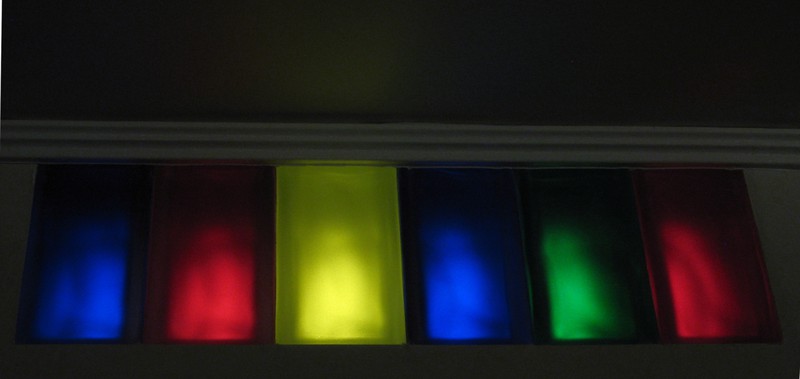
During the last renovation, there was a space between the ceilings about 20 cm high over the bathroom, including the kitchen. It was decided not to close it back completely, but to insert several colored glass blocks with light bulbs behind. Time passed, the glass blocks stood in place for half a year, and finally my hands reached the light bulbs. Of course, just turning them on with the overhead light was not interesting, and I wanted to make them show something.
Then a raspberry pi computer arrived, and the project began to take shape. I will not tell you that I soldered everything in one evening, it was rather months.
')
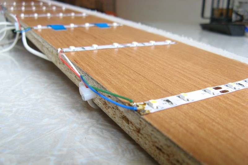
As a source of light took the trim diode tape from the ceiling light in the kitchen. The tape is the simplest, 6W / m, powered by 12V (old universal notebook power supply). At about this time, the overhead light also wanted to be controlled, so that there were seven controlled lines, not six.

Yellow glass shines brighter than others, we will make it weaker with the help of blue electrical tape
To turn the light on and off, open one of the contacts to the LED strip (0 or + 12V). The zero turned out to be simpler, it allowed us to combine the zeros of a 12-volt BP lighting and a 5-volt BP pi. In the bins there were IRLML6344TRPBF transistors (although almost any would fit). They can switch up to 5A and up to 30V, and switch for 30ns (pull any fast PWM). We put one on each line. It turned out this scheme:
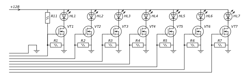
Left control lines. LEDs are schematically indicated, each character is a piece of diode tape
So that the control leg of the transistors does not hang out in the air, I hooked it through 15 kOhm (again, no matter how much, preferably more) to zero for all transistors. For the first line (upper light), we built a divider R1: R11 (15kOhm: 45kOhm) so that it was turned on by default.
I did not want to cling tightly to this scheme, and it will be located in an inaccessible place, so you need to connect an eight-wire cable (seven control lines and ground) ... stop, I know the suitable cable!
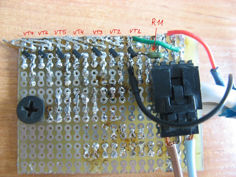
Here is the same scheme from a piece of breadboard, SMD transistors and old resistances:
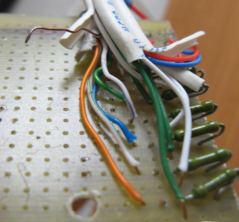
At this end, the twisted pair is soldered, and at the other end the wires stick out

One connector - for the power supply, the second - for the wire to the upper light
Connect - the light is on. We short wires with the fact that by default it is turned on - the lights blink. The order of the legs can not remember, the main thing to distinguish the earth (brown). Compress the other end and do everything beautifully:
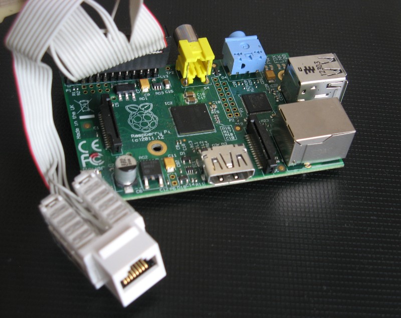
Pi has a lot of free legs
We try!
Everything, now nothing prevents to turn on the light from anywhere:
To control the GPIO, the webiopi library is used (gives the HTTP REST interface to the legs).
It turned out that it was inconvenient to turn on the light from the phone (who would doubt!), So the lamps were programmed to work independently. Now they show the color of Yandex traffic jams in color. Share this in the next episode?
Then a raspberry pi computer arrived, and the project began to take shape. I will not tell you that I soldered everything in one evening, it was rather months.
')
As a source of light took the trim diode tape from the ceiling light in the kitchen. The tape is the simplest, 6W / m, powered by 12V (old universal notebook power supply). At about this time, the overhead light also wanted to be controlled, so that there were seven controlled lines, not six.
Yellow glass shines brighter than others, we will make it weaker with the help of blue electrical tape
To turn the light on and off, open one of the contacts to the LED strip (0 or + 12V). The zero turned out to be simpler, it allowed us to combine the zeros of a 12-volt BP lighting and a 5-volt BP pi. In the bins there were IRLML6344TRPBF transistors (although almost any would fit). They can switch up to 5A and up to 30V, and switch for 30ns (pull any fast PWM). We put one on each line. It turned out this scheme:
Left control lines. LEDs are schematically indicated, each character is a piece of diode tape
So that the control leg of the transistors does not hang out in the air, I hooked it through 15 kOhm (again, no matter how much, preferably more) to zero for all transistors. For the first line (upper light), we built a divider R1: R11 (15kOhm: 45kOhm) so that it was turned on by default.
I did not want to cling tightly to this scheme, and it will be located in an inaccessible place, so you need to connect an eight-wire cable (seven control lines and ground) ... stop, I know the suitable cable!
Here is the same scheme from a piece of breadboard, SMD transistors and old resistances:
At this end, the twisted pair is soldered, and at the other end the wires stick out
One connector - for the power supply, the second - for the wire to the upper light
Connect - the light is on. We short wires with the fact that by default it is turned on - the lights blink. The order of the legs can not remember, the main thing to distinguish the earth (brown). Compress the other end and do everything beautifully:
Pi has a lot of free legs
We try!
Everything, now nothing prevents to turn on the light from anywhere:
To control the GPIO, the webiopi library is used (gives the HTTP REST interface to the legs).
It turned out that it was inconvenient to turn on the light from the phone (who would doubt!), So the lamps were programmed to work independently. Now they show the color of Yandex traffic jams in color. Share this in the next episode?
Source: https://habr.com/ru/post/173013/
All Articles