Homemade thermal imager based on Arduino for less than $ 100
It is no secret that each of us at least once, but dreamed of getting his hands on a real thermal imager. After all, this is a unique chance to look at the world around with absolutely “different eyes”, to see the hidden and perhaps even more deeply understand the essence of some phenomena. And the only obstacle to this dream is the price of such devices. Despite all the progress, it remains prohibitively high for the mere mortal.
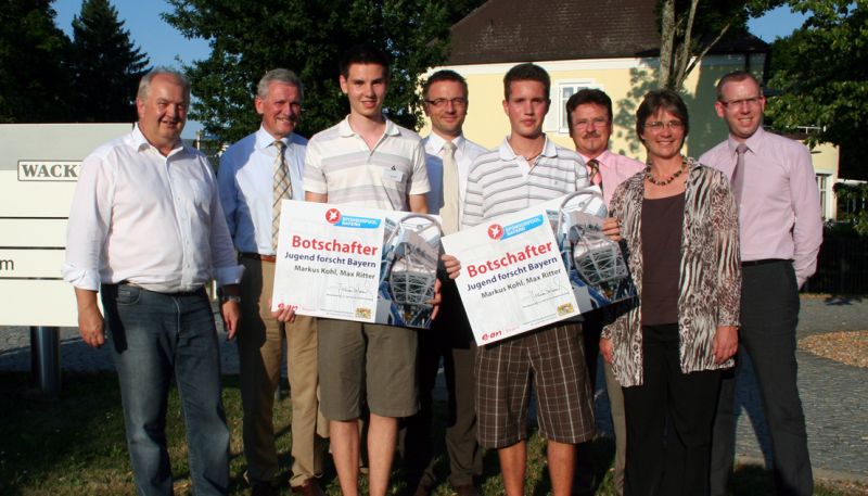
However, like a ray of light in the impenetrable darkness of hopelessness, the development of two students from Germany appeared on the light. Their device based on the Arduino microcontroller is fairly simple to manufacture and has existed since 2010.
The creators of this miracle are Max Ritter and Mark Cole from the city of Mindelheim, in Germany. Their project brought them an award at the scientific and technical youth forum in 2010, and since then the source has a network with a detailed description of the design.
The low cost of the device is achieved through the use of a single temperature sensor MLX90614, similar to that used in the pyrometers and the system of mechanical scanning of the image, consisting of two servo drives. Thus, the sensor essentially bypasses the future picture, point by point scanning the temperature. By itself, this translates into a long time of image acquisition, which is the main drawback of the home-made thermal imager. But after all, if you remember how much we have saved on the price, the eyes close themselves on this.
So, from the components to create a device, you will need:
- An old webcam is, of course, working;
- Arduino microcontroller;
- Servos, 2 pieces;
- Temperature sensor MLX90614-BCI;
- Chinese laser pointer;
- Cases for servo drives;
- Any tripod (optimal).
- Two 4.7kΩ resistors.
Webcam
The camera here will be the source of the original image as well as a kind of viewfinder for the scan area. Almost any cheap webcam will do. I found the good old Logitech in my mess. If the approach to the question is practical, the smaller the webcam in size, the better. Therefore, the huge body of my old woman had to be removed.
')
Servos and mounts
By this time, too, you can approach with a large scale. We will need 2 servos - one will be responsible for vertical movement, the second horizontally, respectively. Considering that the vertical drive and the webcam itself are held on a horizontal drive, it is worth taking a more powerful one. Although many have already made the device quietly enjoy the same low-power.
Mounts for servo drives in the original are called "tilt-swivel mechanism" and we have a "Servo bracket"
I bought all these components here .
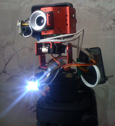
Assembled, this structural element looks like this:

The bottom drive is attached to a tripod or another case / stand, where you also need to insert a laser pointer, a webcam and MLX90614 sensor are attached to a vertical servo drive by tricky manipulations with glue or parts from the designer or for example with spare parts from old electricity meters (like mine).
Temperature sensor MLX90614-BCI
The most difficult part of this design. Difficult in terms of production. Find it is not easy (at least on domestic sites) and it is the most expensive part of the design. I myself have been waiting for him for about two months, apparently being transported from China. I can not tell where to take it, because that shop has already been covered. The author of the project refers to Futureelectronics .
When choosing, it is necessary to pay special attention to the last letters “BCI” in the title, which means that the sensor has a nozzle to ensure a narrow field of view.
It looks like this:

Arduino and wiring diagram
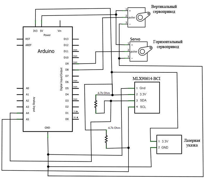
The connection diagram of the sensor and servos to the microcontroller is the simplest:
The Arduino sketch and thermal imaging software can be downloaded here:
Official project page
Software (by JAVA)
Sketch for the microcontroller
I also want to draw attention to the fact that the authors point out the need for additional adjustment of the sensor using a special sketch, which seems to speed up the device. However, in my case, the sensor after the configuration began to produce false temperature values and I did roll back.
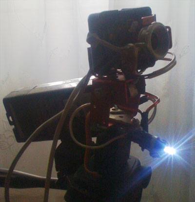
After assembling the whole scheme, it can be placed in the case, and mounted on a tripod:
Small explanations:
As a case for the microcontroller, he took the plastic packaging from under the car freshener (in the photo on the left), which in turn is supported on a tripod with the aid of fasteners from an optical rifle scope. In general, the principle of cheapness and the use of what was at hand was strictly maintained. A flashlight glows in the photo, which was a bonus to a laser pointer and turned out to be very useful when scanning dark areas.
Shooting process
Why do we need a Chinese laser here and how the scanning process takes place is easy to understand with my gorgeous carpet:

Do not be surprised that the software is in Russian, I just have been working on it for some time to fit my needs, while learning the Java language. Unfortunately, while my knowledge is not enough for the final design of the finished product.
So, in the picture from the webcam there are two yellow dots and a dot of our laser (bottom center). The entire calibration is to select the coordinates of the center and the lower left corner of the future thermogram. The laser pointer will help with this:
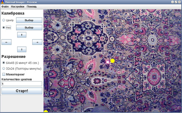
Today's software supports only two types of resolution for the future picture, while the previous version was rich in this matter, with six different resolutions. It was especially fun to get very “pixel” pictures in 15 seconds. I think the developers realized the uselessness of the other modes and removed them, although they remained programmatically and could be activated.
Results for dessert
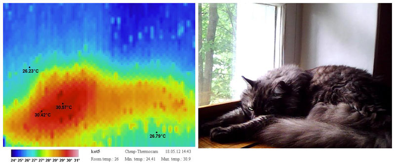
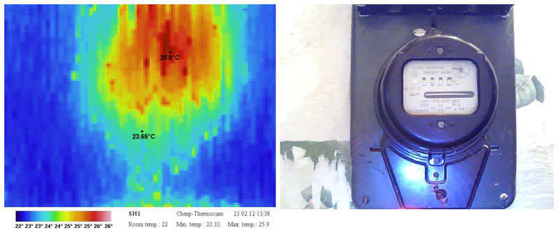
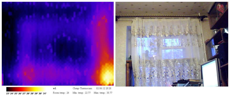
The resulted thermograms in various resolution.
How hot is the netbook:

My cat:
Old counter:
New shield:

Window:
My friend in a dark room in front of a computer

Application
Due to the large scanning time, this device is not suitable for conducting an energy audit (at least for professional use), this issue is discussed in this Article (Eng.) .
Nevertheless, as it seems to me, it could be an excellent tool for checking the heating of electrical connections and power assemblies. In my practice (and I work as an electrician), sometimes I use this imager to assess the reliability of connections. The pyrometer in this case loses in visibility.
Disadvantages in the work associated with the hard binding of the device to the computer and the need to always carry a netbook. For a while, the authors developed the second version of their thermal imager, which was positioned as a separate device with another temperature sensor (which by the way was used in this project ) with its own display and the ability to write to a memory card. But unfortunately, as Max Ritter admitted, he does not have time to complete the project.
In general, the further development of the idea lies on the shoulders of amateurs and craftsmen. I would welcome any suggestions for improvement / improvement of the design.
Thanks for attention!
Official page of the project (Eng.)
Source: https://habr.com/ru/post/172947/
All Articles