Workout NiMH batteries. Is there any reason?
Prologue
It all started with the fact that my photojam flatly refused to work with batteries fresh from the charger - four AA-size NiMHs. They would take, as usual, and throw it away. But for some reason this time curiosity prevailed over common sense (or maybe the toad gave a vote), and wanted to understand - is it possible to squeeze out anything else from these batteries? The camera is very eager for energy, but there are more modest consumers - wireless mice or keyboards, for example.
Actually the parameters interesting to the consumer, two - the capacity of the battery and its internal resistance. Possible manipulations too little - discharge and charge. Measuring in the process of discharge current and time, you can estimate the battery capacity. The difference in battery voltage at idle and under load can be used to estimate the internal resistance. By repeating the discharge-charge cycle (i.e., by performing “training”) several times, one can understand whether this action at all makes sense.
')
Accordingly, such a plan has been formed - we make a controlled discharger and a charger with the possibility of continuous measurement of process parameters, perform simple arithmetic operations on the measured values, repeat the process the necessary number of times. We compare, we draw conclusions, we finally throw out the batteries.
Measuring stand
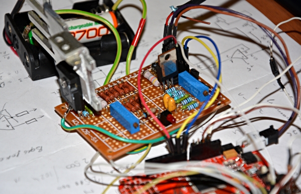
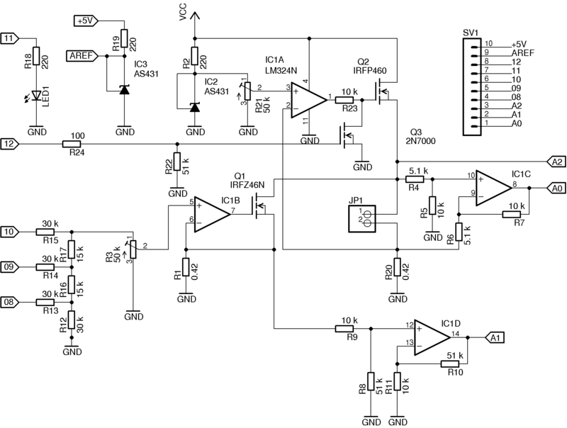
A complete collection of bicycles. It consists of an analog part (in the diagram below) and a microcontroller. In my case, the intellectual part was the Arduino, although this is completely irrelevant - if only there was a necessary set of inputs / outputs.
The stand was made of what was found within a radius of three meters. If someone wants to repeat, it is not at all necessary to follow the pattern exactly. The choice of the parameters of the elements can be quite wide, then I will comment on this for a bit.
The discharge unit is a controlled current regulator at the IC IC1B (LM324N) and the Q1 field-effect transistor. Virtually any transistor, just enough allowable voltages, currents and power dissipation. And they are all small. The feedback resistor and at the same time part of the load (together with Q1 and R20) for the battery is R1. Its maximum value must be such as to ensure the required maximum discharge current. If we assume that the battery can be discharged to 1 V, then to provide a discharge current, for example, in 500 mA, the resistor R1 should not be greater than 2 Ohms. The stabilizer is controlled by a three-bit resistive DAC (R12-R17). Here the calculation is the same - the voltage at the direct input of the op-amp is equal to the voltage at R1 (which is proportional to the discharge current). We change the voltage at the direct input - the discharge current changes. To scale the DAC output to the desired range, there is a trimming resistor R3. It is better that it is multi-negotiable. The ratings of R12-R17 can be any (in the region of tens of kilo-ohms), the main thing is that the ratio of their values is 1/2. Special accuracy from the DAC is not required, since the discharge current (voltage at R1) in the process is measured directly by the IC1D instrumentation amplifier. Its gain is K = R11 / R10 = R9 / R8. The output is fed to the ADC of the microcontroller (A1). By changing the values of R8-R11, the gain can be adjusted to the desired one. The battery voltage is measured by the second IC1C amplifier, K = R5 / R4 = R7 / R6. Why control the discharge current? The point here is basically this. If discharged with a constant high current, then due to the large internal resistance of worn out batteries, the minimum allowable voltage of 1 V (and there is no other guideline to stop the discharge) before the battery is actually discharged. If discharged with a constant low current, the process will stretch too long. Therefore, the discharge is carried out in steps. Eight steps seemed to me enough. If the hunt is more / less, then you can change the width of the DAC. In addition, turning the load on and off, you can estimate the internal resistance of the battery. I think that the algorithm does not require any further explanation of the controller operation. At the end of the process, Q1 is locked, the battery is completely disconnected from the load, and the controller turns on the charge unit.
Block charge. Also a current stabilizer, only unmanaged, but disconnectable. The current is set by the reference voltage source on IC2 (2.5 V, accuracy 1% according to the date) and resistor R21. In my case, the charge current was classic - 1/10 of the nominal battery capacity. Feedback Resistor - R20. The reference voltage source can be used any other - for your taste and availability of parts. Transistor Q2 operates in a more rigid mode than Q1. Due to the noticeable difference between the voltage Vcc and the battery voltage, noticeable power is dissipated on it. This is a fee for the simplicity of the scheme. But the radiator saves the day. Transistor Q3 is used to forcibly lock Q2, i.e., to disconnect the charge unit. It is controlled by a 12 microcontroller signal. Another source of reference voltage (IC3) is needed for the operation of the ADC controller. The accuracy of measurements of our stand depends on its parameters. LED1 - for indicating the status of the process. In my case, it does not burn during the discharge process, it lights when charging and flashes when the cycle is over.
The supply voltage is chosen so as to ensure the opening of the transistors and their work in the right ranges. In this case, both transistors unlock the voltage of the gate is quite high - about 2-4 V. In addition, Q2 "propped" the battery voltage and R20, so the unlocking voltage at the gate starts from about 3.5-5.5 V. In turn The LM323 cannot raise the output voltage above Vcc minus 1.5 V. Therefore, the Vcc should be large enough and in my case equal to 9 V.
The charge control algorithm was based on the classic version of the control of the beginning of the voltage drop across the battery. However, in fact, it turned out that everything was not quite so, but more on that later.
All measured values in the process of "research" were written to a file, then calculations were made and graphs were built.
I think that everything is clear with the measuring bench, so let’s move on to the results.
Measurement results
So, we have charged (but not working) batteries, which we discharge and measure the stored capacity, and at the same time the internal resistance. It looks like this.
Charts in axes time, clock (X) and power, W (Y) for the best and worst of the batteries. It can be seen that the stored energy (the area under the graphs) is significantly different. In numerical terms, the measured battery capacity was 1196, 739, 1237 and 1007 mA * h. Not much, given that the nominal capacity (which is indicated on the case) - 2700 mAh. And the spread is quite large. And what about internal resistance? It was 0.39, 0.43, 0.32 and 0.64 ohms, respectively. Awful. It is clear why the soap dish refused to work - the batteries simply were not able to release a large current. Well, let's start training.
Cycle one. Again, the power given to the best and worst battery.

Progress is visible to the naked eye! Numbers confirm this: 1715, 1444, 1762 and 1634 mA * h. Internal resistance is also prettier, but very uneven - 0.23, 0.40, 0.1, 0.43 ohms. It would seem there is a chance. But alas - further discharge / charge cycles yielded nothing. The values of capacitance, as well as internal resistance, varied from cycle to cycle within about 10%. What lies somewhere close to the limits of measurement accuracy. Those. Long training, in any case for my batteries, did not give anything. But it became clear that the batteries retained more than half of the capacity and will work quite well on low current. At least some economy in the economy.
Now I want to dwell a bit on the charge process. Perhaps my observations will be useful to someone who is going to construct an intelligent charger.
Here is a typical graph of charge (on the left is the battery voltage scale in volts).
After the start of the charge, a voltage drop is observed. In different cycles it may be more or less in depth, of slightly different duration, sometimes absent. Then for about 10 hours there is a uniform growth and then an exit to the almost horizontal plateau. The theory says that at a low charge current, there is no voltage drop at the end of the charge. I had patience and still waited for this fall. It is small (almost unnoticeable on the chart), you need to wait for a very long time, but it always is. After ten hours of charge and before the fall, the voltage on the battery, though growing, is extremely insignificant. It almost does not affect the final charge, some unpleasant phenomena such as heating the battery is not observed. Thus, when designing low-voltage chargers, there is no sense in supplying them with intelligence. A timer for 10-12 hours is enough, and no special accuracy is required.
However, this idyll was broken by one of the elements. After about 5-6 hours of charge, very noticeable voltage fluctuations occurred.
At first I wrote it off as a constructive flaw in my booth. The photo shows that everything was assembled by mounting, and the controller was connected with rather long wires. However, repeated experiments have shown that such nonsense stably arises with the same battery and never arises with others. To my shame, I did not find the reason for this behavior. Nevertheless, (and on the graph it is clearly seen) the average value of the voltage grows as it should.
Epilogue
As a result, we have four batteries, which the ecological niche was found by exact scientific methods. We are disappointed in the possibilities of the training process. And we have one unexplained effect that occurs when the charge.
The next is a bigger battery - a car battery. But there the load resistors are a couple of orders of magnitude more powerful. Somewhere go across the expanses of Eurasia.
That's all. Thanks for attention.
Source: https://habr.com/ru/post/172587/
All Articles