Report on the maintenance of the base station standards GSM and UMTS
Dear Habravchane, in view of my work activity for the benefit of the federal mobile operator "three letters", I constantly come across the equipment of the radio subsystem of 2G / 3G networks and the surrounding infrastructure. Accordingly, during the work of the “baseman”, there appeared a desire to share with the public information about how the base station of the radio access network is in reality. I will not give you the diagrams of the device of mobile communication networks, because there is enough information on the Internet both via GSM and UMTS, and I will show you a voluminous photo report of the maintenance of the object.
')
So, the radio access network of GSM or UMTS standards consists of the N-th number of base stations. Base stations (BS) are controlled by a BSC / RNC controller or several controllers. User traffic and signaling information from BS and controllers is delivered to the Core Network, consisting of a switch, transcoders , media gateways, packet-switched access nodes , etc.
Thus, the radio subsystem includes base stations and their controllers, which I deal with directly. The location point of the BS is referred to as the site / platform / hardware. Periodically, maintenance of the BS, the power supply system, the transport network equipment, the fire alarm system, the automatic fire extinguishing system, the antenna mast structures and the feeder path are performed at certain sites.
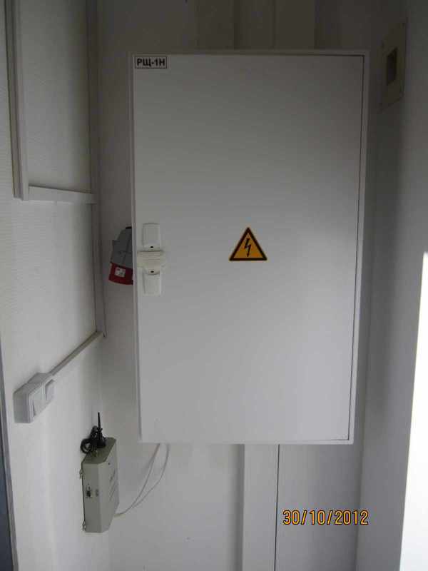
The power supply system consists of an introductory shield.
Three-phase power supply with the possibility of a backup connection from the generator.
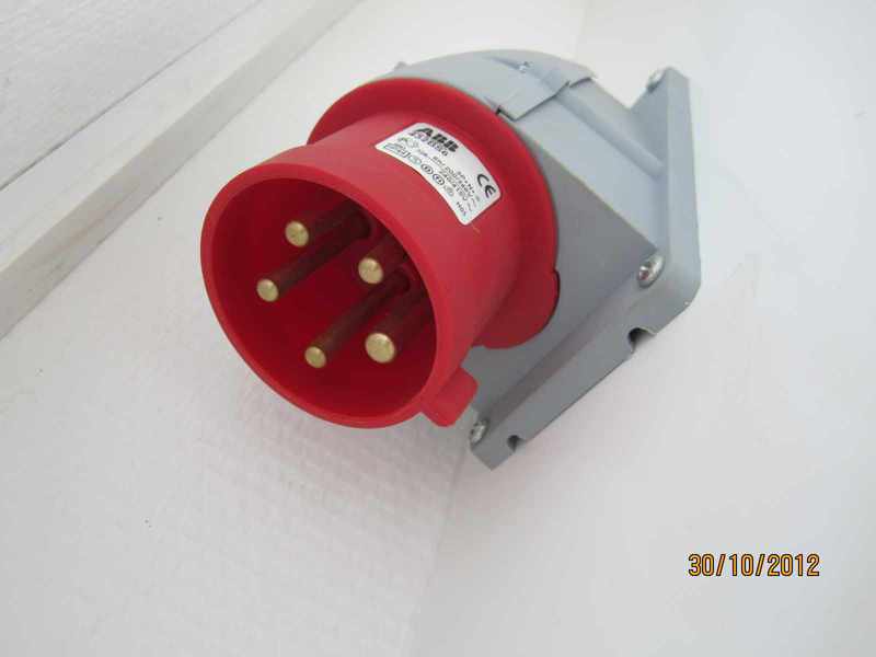
Socket connecting the cable from the mobile generator.
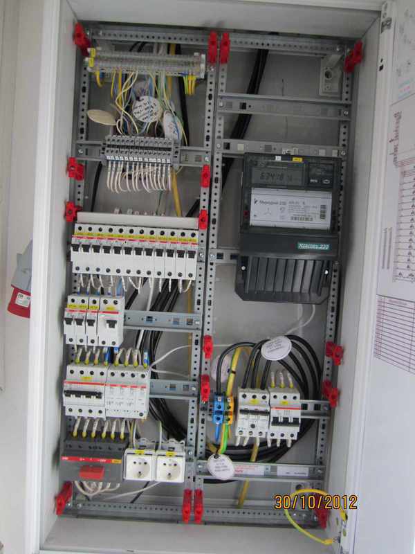
There are electricity meter, additional sockets, surge suppressors and automatic machines of various denominations for electricity consumers: air conditioners, work lamps and emergency lighting, uninterruptible power supply (UPS), fire alarm, heater, exhaust ventilation.
The most important elements of the radio access network are powered from the DC network with a voltage of -48 V, although domestic equipment was designed for -60 V from Soviet times. In the event of a power outage, the power supply organizations for various reasons have backup power from the batteries.
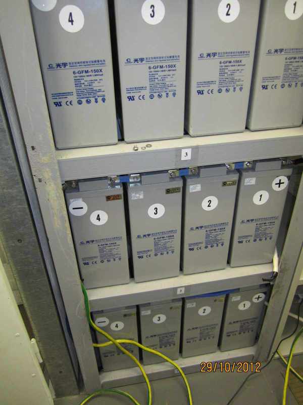
This facility has 3 Coslight 6-gfm-150x batteries each with a capacity of 150 Ah. By the way, the numbering of batteries in the photo is correct from the positive to negative terminals. During battery maintenance, a check digit is performed using a block of load resistors . According to the results of the discharge, it is concluded whether the battery requires replacement or not.
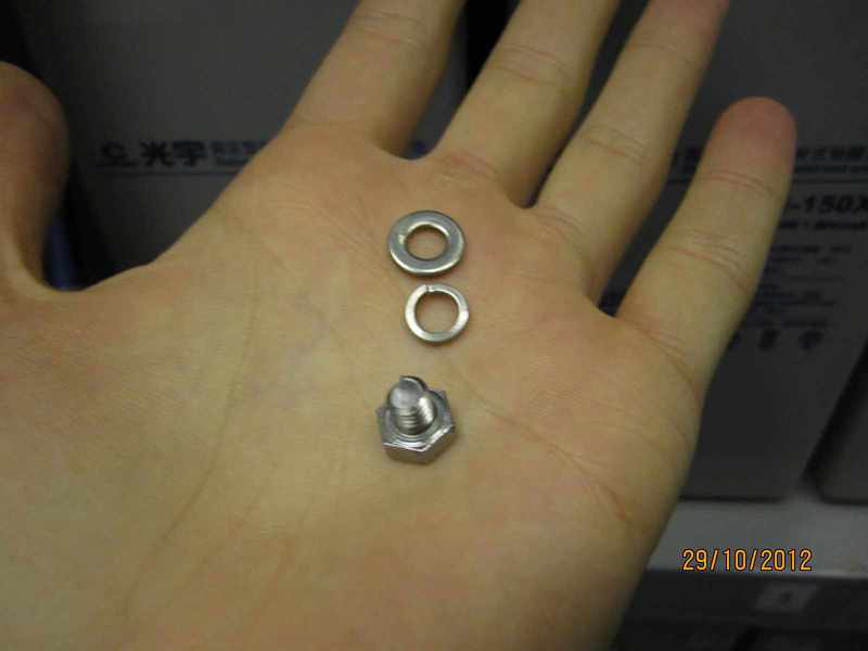
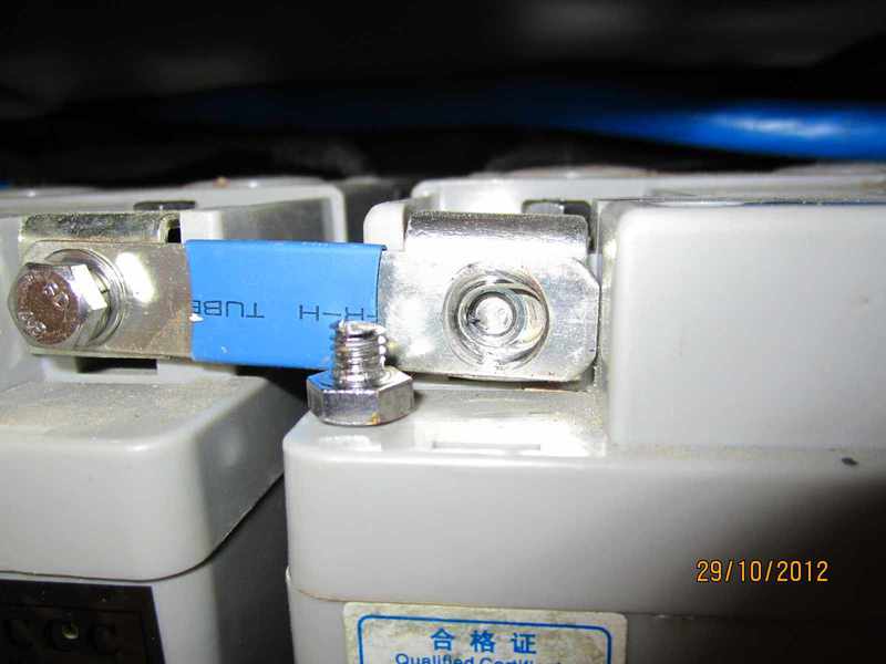
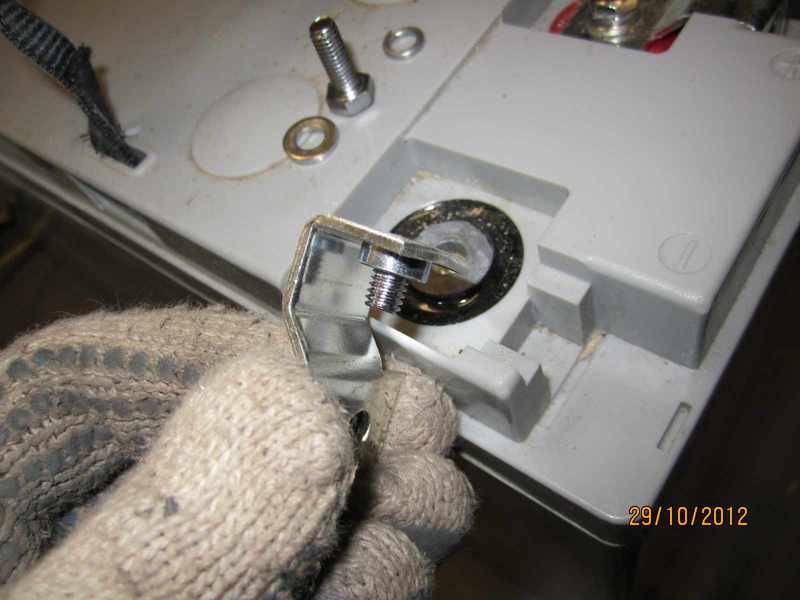
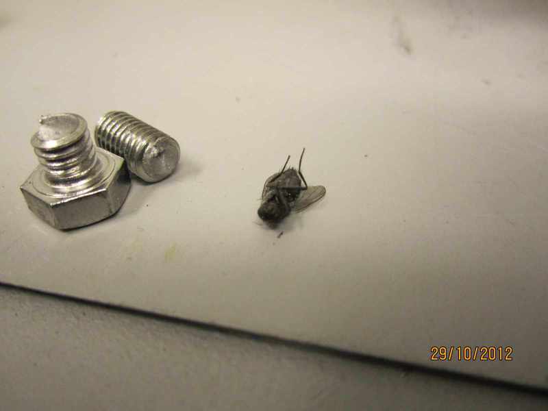
By the way, about the quality of products from China. When checking the tightening torque of the battery jumper bolts, the following happened.
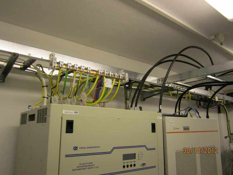
The conversion of AC to DC and battery content is controlled by an uninterruptible power supply.
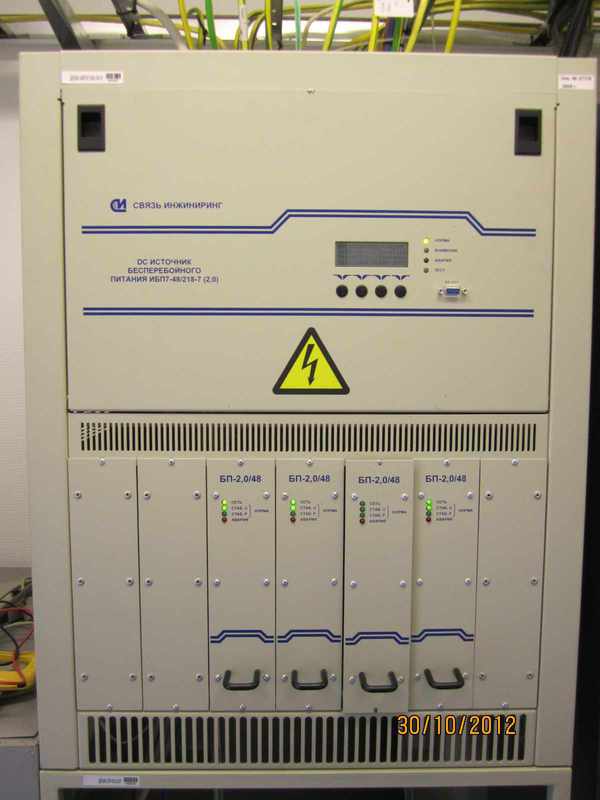
In this UPS 7-48 / 218-7 (2,0) 4 blocks of pulse stabilization are installed.

On the UPS indicator, we observe a constant voltage of 54.1 V, a load current of 32 A, a battery charge current of 0 A and a temperature on the rack with battery +18 degrees Celsius (the thermal sensor is required for thermal compensation of the battery content).
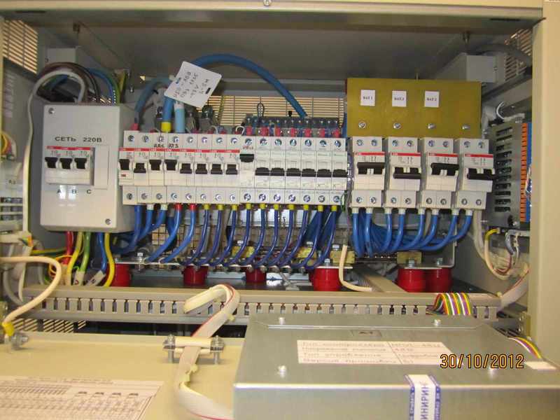
Behind the cover of the UPS there is a row of automata, from which wires are pulled to base stations, radio relay stations (RRS), batteries, and other DC consumers. In the same place, on the left, there is a scarf with contacts for the output of an external alarm signal on power outage and battery discharge.
In a particular case, the site was a base station of GSM 900 standard manufactured by Alcatel.
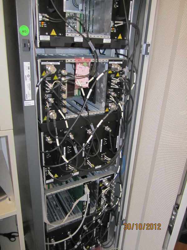
Behind the cabinet door is the main equipment: 10 TRAGE transmitters, 3 AGC9E combiners, and one SUMA control board. The BS configuration is described as 4/3/3, which means: the first sector has 4 transmitters, the second and third each have 3. Each transmitter is connected to the combiner of the designated sector. From the combiner go 2 feeders (jumper) to lightning protection and further upward to the antenna of the selected sector.
On the top of the cabinet, from the left to the right, there are 2 skirting boards for external accidents, a skirting for connecting to the transport network via the A-bis interface (E1 flows), power contacts (blue and black wires) and switches, each for a separate cabinet shelf.
6 jumpers (specifically for the three-sector configuration) come out from the top of the BS cabinet and are connected to an external feeder path (7/8 inch feeder diameter) through lightning protection.

Lightning protection
Cable entry is hermetically sealed from moisture.

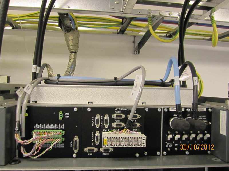
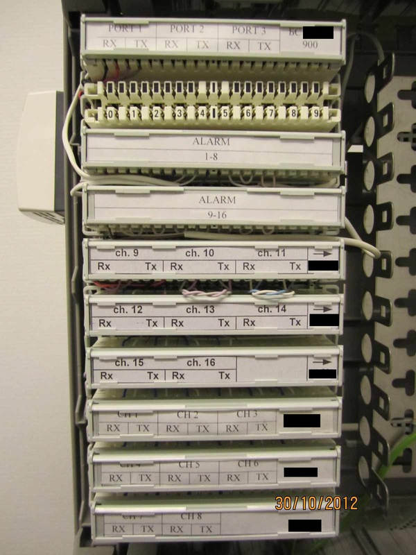
A 19 "rack is installed in the corner. The cross, internal PPC units and a UMTS base station are located in it.
The internal unit (IDU) PPC is connected to the external unit (ODU) by the black feeder 8D-FB. In 2 IDU connectors are connected cables, each of which outputs 8 E1 streams to the cross. The patchcord of port 1 is connected to the transport port of the UMTS base station.
Relayka MDP-34MB-25C capable of passing 34 Mbps of traffic, indeed, is not enough.
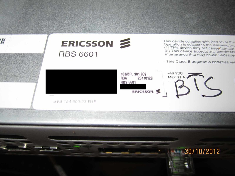
Below is the baseband Ericsson RBS 6601 standard UMTS (3G).
External transmitters are connected by an optical cable with an indoor unit.
Excess optics are neatly wound, packed and fixed on the wall.
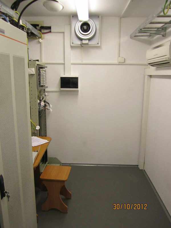
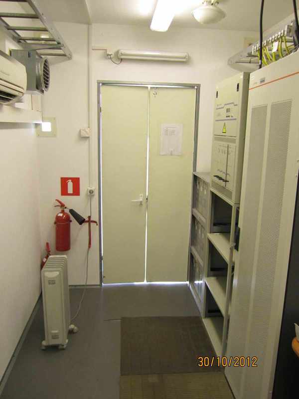
View of the hardware from the entrance.
Opposite side.
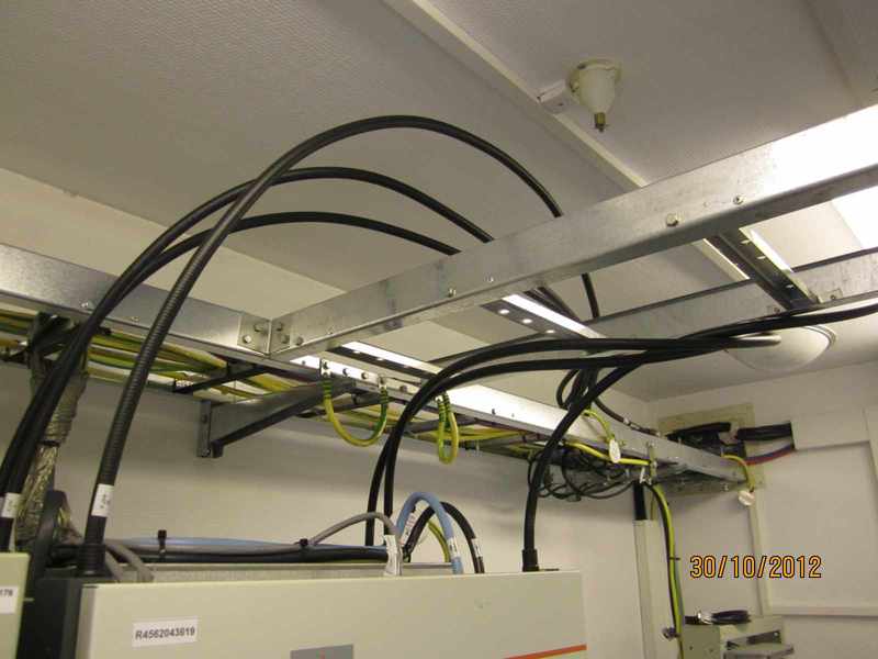
Kabelrost with the main grounding tire (GZSh).
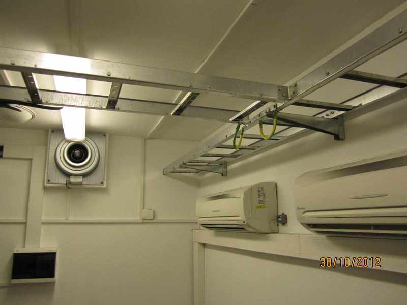
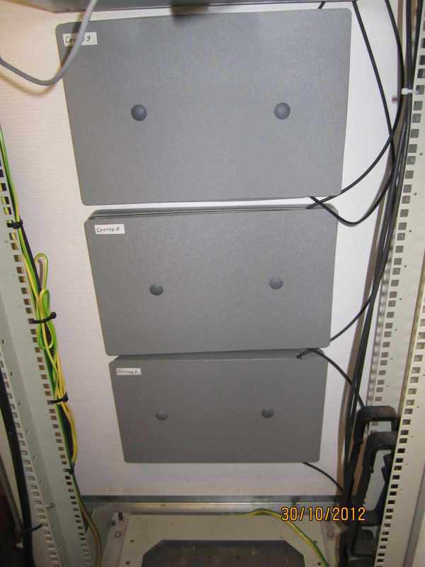
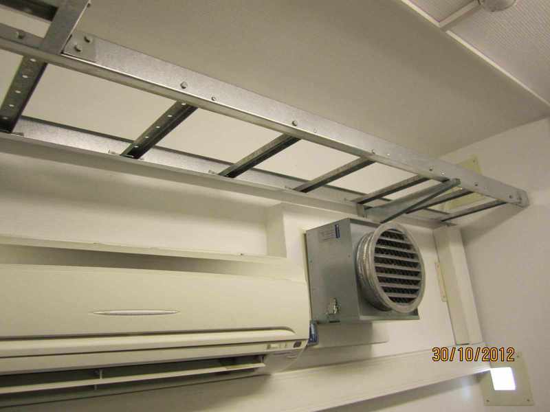
Empty cabrost, hood, air conditioners, bottom left shield with automatic machines for external transmitters (RRU) UMTS base.
Duct ventilation.
Actually plinth cross.

Heater and fire extinguishers.
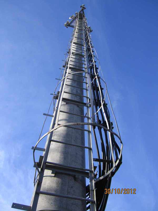
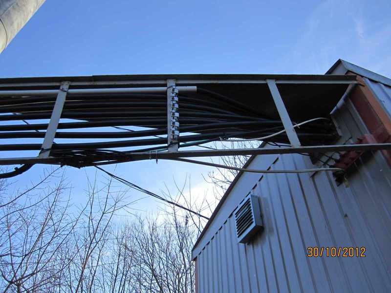
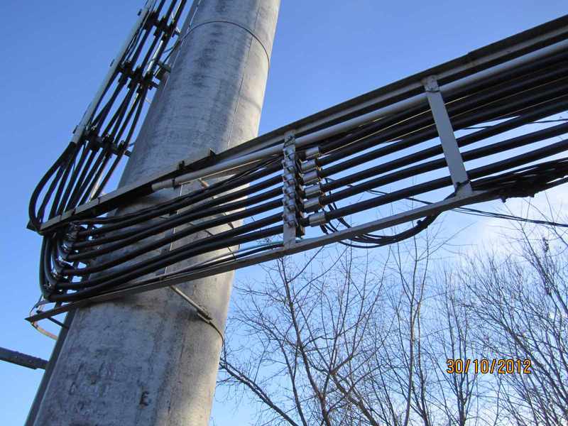
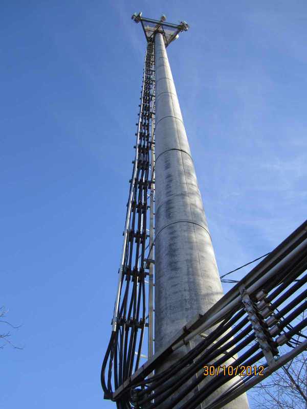
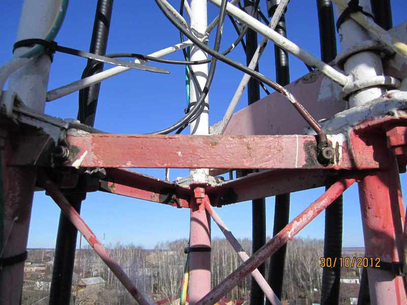
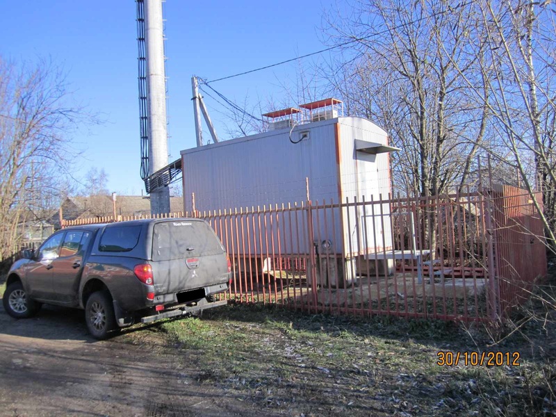
Let's see what is outside the hardware BS. An iron-concrete pillar is installed as an antenna mast support, a separate story can be added up about the posts, since they are not designed for real load. In the near future, they will be replaced with all-metal bearings.
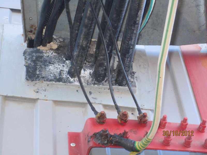
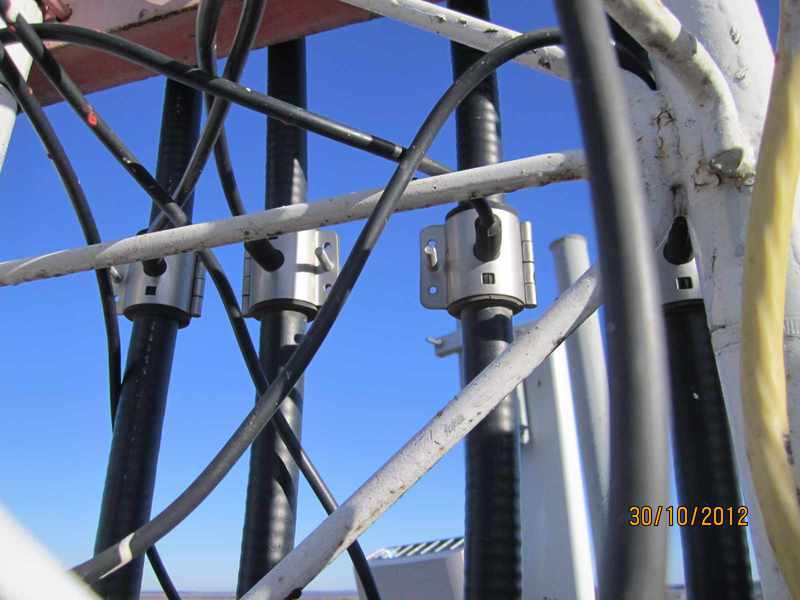
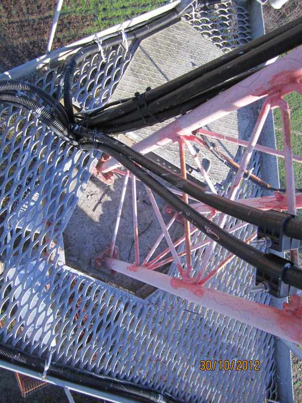
View cable entry outside. 6 feeders from GSM to antennas, in corrugation 3 optical cables, 3 black power cables of 3G transmitters, from which thin black ground wire cables go to the red bus, yellow-green wire - grounding of the outdoor PPC unit.
Next photo of the external cable.
Anti-icing protection.
Ladder with safety fence.
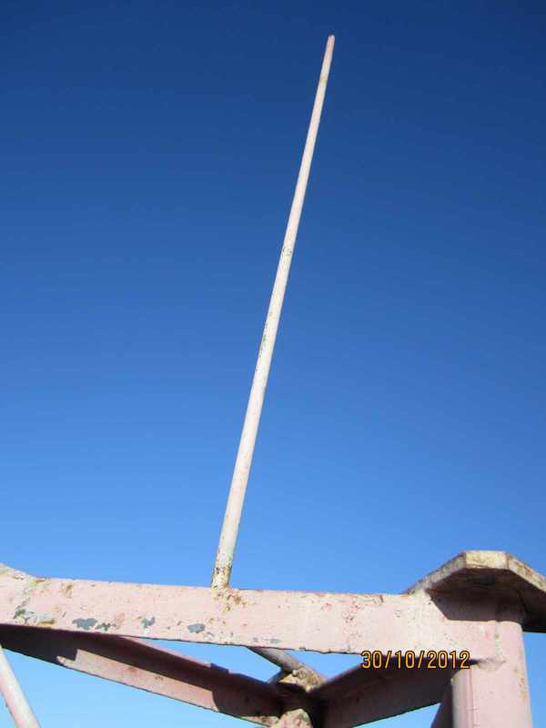
At the top of the pillar is a metal basket with a superstructure, which is closed by a lightning spire.
The pipe stand and sector antenna BS GSM standard installed on it.

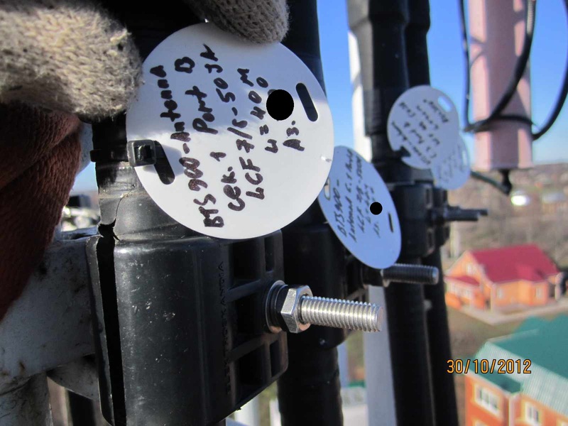
Marking the sector is made for easy orientation in case of modernization or elimination of accidents.
Antenna connectors with fixed jumpers. Jumpers with a length of 1.5 to 3 meters and a diameter of 1/2 inch.
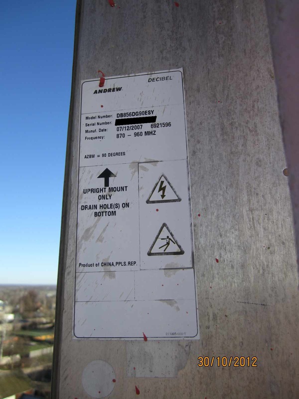
GSM sector antenna label.
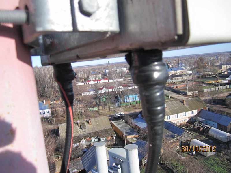
A pair of jumpers from the feeders to the antenna.
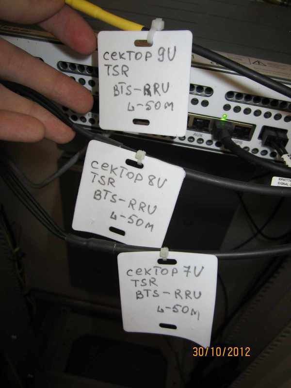
Marking of feeders using tags.
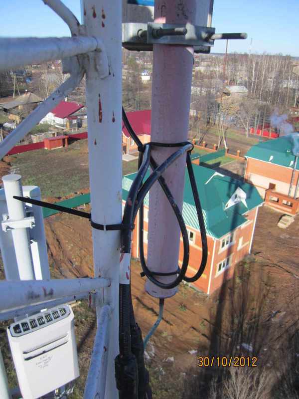
Grounding feeders.
Grounding points for feeders on a metal structure.
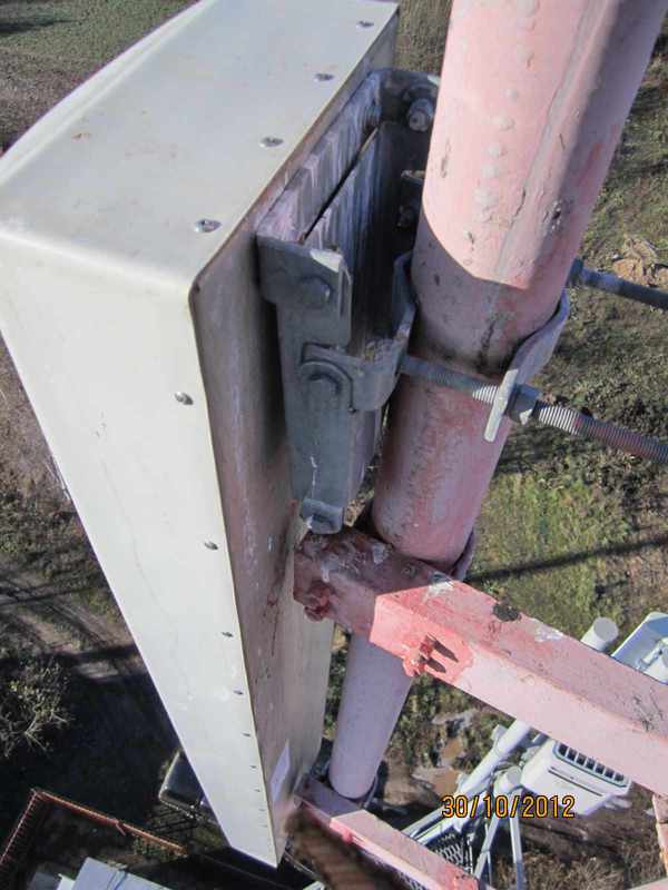
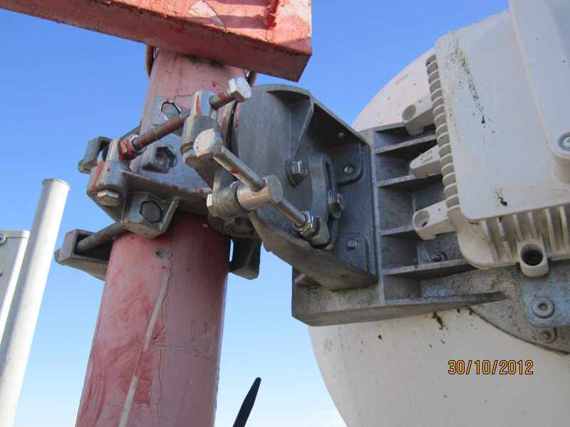
Tube with antenna and external PPC unit.
Marked antenna RRS.

RRL flight, visible hub tower in the distance.
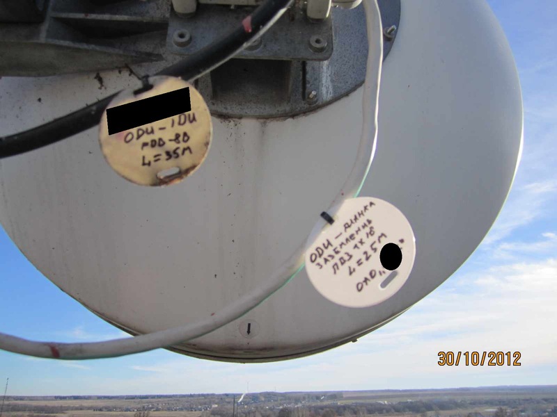
Label on the outdoor PPC unit.
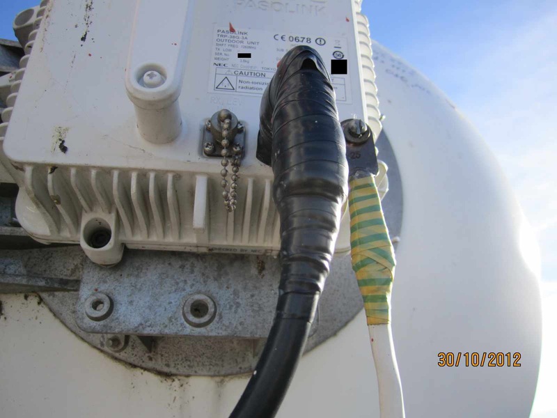
In the top photo, the leftmost connector is used to connect a voltmeter when adjusting (adjusting) the span, the voltage at this connector is proportional to the level of the received signal from the response relay. The next connector for connecting the ODU and IDU (outdoor unit & indoor unit) PPC is a coaxial IF cable (intermediate frequency). The connector is sealed against moisture in the cable. Extreme right point for block grounding.
Labeling of cables PPC.
Actually fixture antenna RRS. Two long screws / studs are used for fine adjustment of the RRL span.
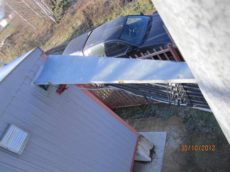
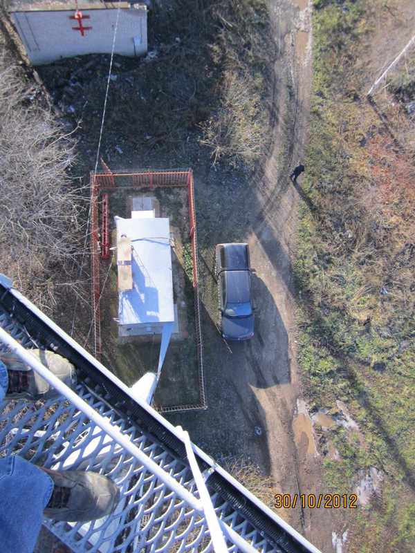
View of the site from above.
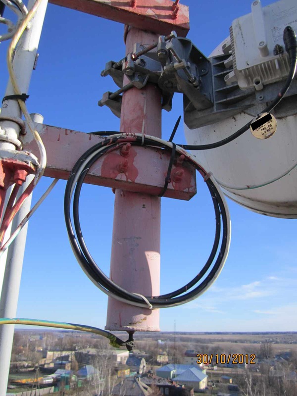
RRU - remote radio unit standard UMTS.
What is connected to the RRU? On the left, a thin optical cable comes in from the corrugations into the transmitter, inside which a conventional SFP module is installed. Next comes the power cable (also -48 V, DC). To the right is a thin cable for connecting to RET (Remote Electrical Tilt) - a device that controls the electric angle of the sector antenna. Then 2 jumpers to the antenna and a yellow-green ground cable.
It should be explained why antennas with cross-polarization are used that in GSM, that in UMTS. In fact, there are 2 antennas with different polarization (usually angles of +45 degrees and -45 degrees) in the case, so 2 feeders from the transmitters are connected. Thus, polarization diversity of the signal received from the subscriber is realized.
Label on UMTS antenna.
Ret behind.

RET from the front of the antenna.
View of the top of the hardware (30 m).

BS of competitors with a climatic case in which all necessary for work is established.
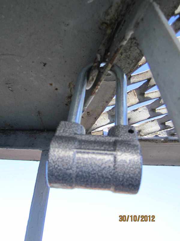
After the end of the work we close the hatch to the site from the "vandals".
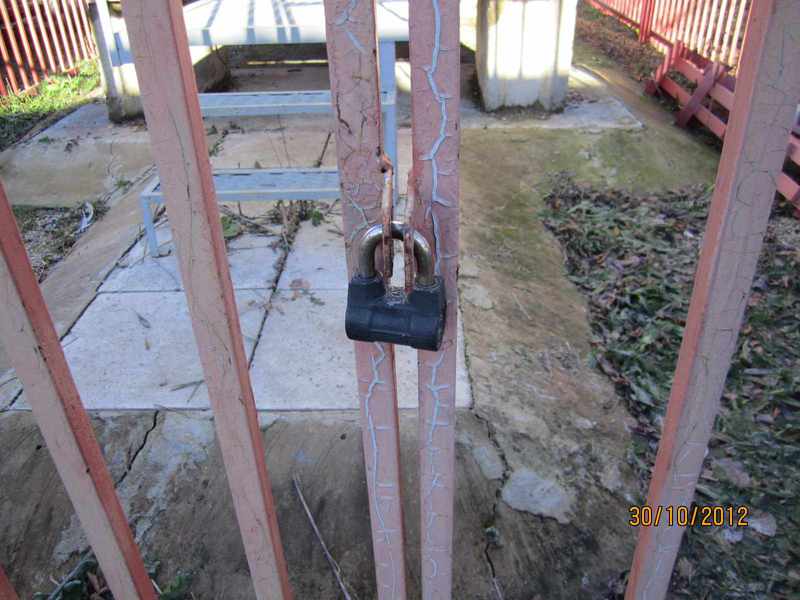
Closing the site fencing ...
... we are loading into pepelats and going to rest.
I hope this small photo report will show you how the usual base station of mobile communication is built and how, approximately, everything is implemented in hardware. I apologize for the quality of the photo, the shooting was carried out in working order. The post was written for an invite to Habr with the hope of new interesting publications.
PS As a suggestion: “There is no disclosure of corporate information in the post!”
PPS Thank @FakeFactFelis for an invite.
')
So, the radio access network of GSM or UMTS standards consists of the N-th number of base stations. Base stations (BS) are controlled by a BSC / RNC controller or several controllers. User traffic and signaling information from BS and controllers is delivered to the Core Network, consisting of a switch, transcoders , media gateways, packet-switched access nodes , etc.
Thus, the radio subsystem includes base stations and their controllers, which I deal with directly. The location point of the BS is referred to as the site / platform / hardware. Periodically, maintenance of the BS, the power supply system, the transport network equipment, the fire alarm system, the automatic fire extinguishing system, the antenna mast structures and the feeder path are performed at certain sites.
The power supply system consists of an introductory shield.
Three-phase power supply with the possibility of a backup connection from the generator.
Socket connecting the cable from the mobile generator.
There are electricity meter, additional sockets, surge suppressors and automatic machines of various denominations for electricity consumers: air conditioners, work lamps and emergency lighting, uninterruptible power supply (UPS), fire alarm, heater, exhaust ventilation.
The most important elements of the radio access network are powered from the DC network with a voltage of -48 V, although domestic equipment was designed for -60 V from Soviet times. In the event of a power outage, the power supply organizations for various reasons have backup power from the batteries.
This facility has 3 Coslight 6-gfm-150x batteries each with a capacity of 150 Ah. By the way, the numbering of batteries in the photo is correct from the positive to negative terminals. During battery maintenance, a check digit is performed using a block of load resistors . According to the results of the discharge, it is concluded whether the battery requires replacement or not.
By the way, about the quality of products from China. When checking the tightening torque of the battery jumper bolts, the following happened.
The conversion of AC to DC and battery content is controlled by an uninterruptible power supply.
In this UPS 7-48 / 218-7 (2,0) 4 blocks of pulse stabilization are installed.
On the UPS indicator, we observe a constant voltage of 54.1 V, a load current of 32 A, a battery charge current of 0 A and a temperature on the rack with battery +18 degrees Celsius (the thermal sensor is required for thermal compensation of the battery content).
Behind the cover of the UPS there is a row of automata, from which wires are pulled to base stations, radio relay stations (RRS), batteries, and other DC consumers. In the same place, on the left, there is a scarf with contacts for the output of an external alarm signal on power outage and battery discharge.
In a particular case, the site was a base station of GSM 900 standard manufactured by Alcatel.
Behind the cabinet door is the main equipment: 10 TRAGE transmitters, 3 AGC9E combiners, and one SUMA control board. The BS configuration is described as 4/3/3, which means: the first sector has 4 transmitters, the second and third each have 3. Each transmitter is connected to the combiner of the designated sector. From the combiner go 2 feeders (jumper) to lightning protection and further upward to the antenna of the selected sector.
On the top of the cabinet, from the left to the right, there are 2 skirting boards for external accidents, a skirting for connecting to the transport network via the A-bis interface (E1 flows), power contacts (blue and black wires) and switches, each for a separate cabinet shelf.
6 jumpers (specifically for the three-sector configuration) come out from the top of the BS cabinet and are connected to an external feeder path (7/8 inch feeder diameter) through lightning protection.
Lightning protection
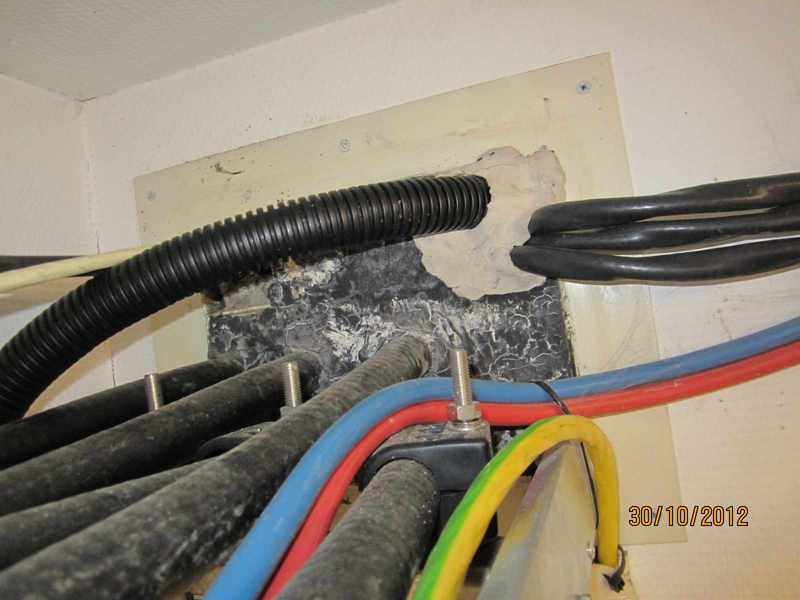
Cable entry is hermetically sealed from moisture.
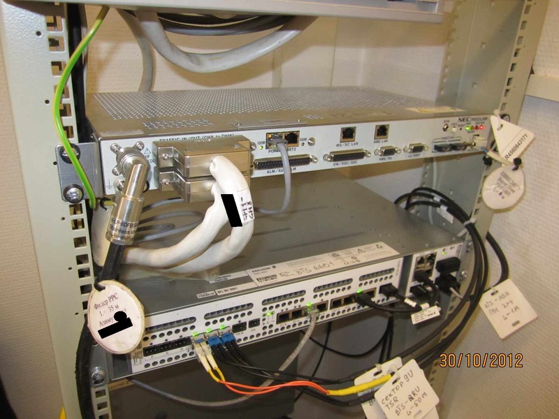
A 19 "rack is installed in the corner. The cross, internal PPC units and a UMTS base station are located in it.
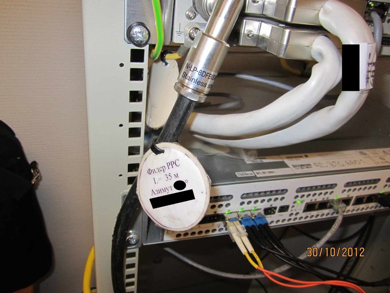
The internal unit (IDU) PPC is connected to the external unit (ODU) by the black feeder 8D-FB. In 2 IDU connectors are connected cables, each of which outputs 8 E1 streams to the cross. The patchcord of port 1 is connected to the transport port of the UMTS base station.
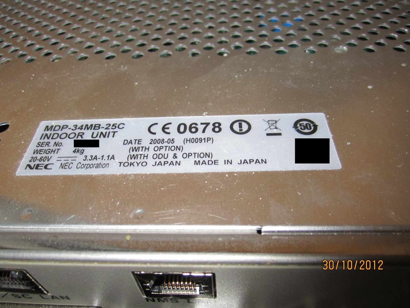
Relayka MDP-34MB-25C capable of passing 34 Mbps of traffic, indeed, is not enough.
Below is the baseband Ericsson RBS 6601 standard UMTS (3G).
External transmitters are connected by an optical cable with an indoor unit.
Excess optics are neatly wound, packed and fixed on the wall.
View of the hardware from the entrance.
Opposite side.
Kabelrost with the main grounding tire (GZSh).
Empty cabrost, hood, air conditioners, bottom left shield with automatic machines for external transmitters (RRU) UMTS base.
Duct ventilation.
Actually plinth cross.
Heater and fire extinguishers.
Let's see what is outside the hardware BS. An iron-concrete pillar is installed as an antenna mast support, a separate story can be added up about the posts, since they are not designed for real load. In the near future, they will be replaced with all-metal bearings.
View cable entry outside. 6 feeders from GSM to antennas, in corrugation 3 optical cables, 3 black power cables of 3G transmitters, from which thin black ground wire cables go to the red bus, yellow-green wire - grounding of the outdoor PPC unit.
Next photo of the external cable.
Anti-icing protection.
Ladder with safety fence.
At the top of the pillar is a metal basket with a superstructure, which is closed by a lightning spire.
The pipe stand and sector antenna BS GSM standard installed on it.
Marking the sector is made for easy orientation in case of modernization or elimination of accidents.
Antenna connectors with fixed jumpers. Jumpers with a length of 1.5 to 3 meters and a diameter of 1/2 inch.
GSM sector antenna label.
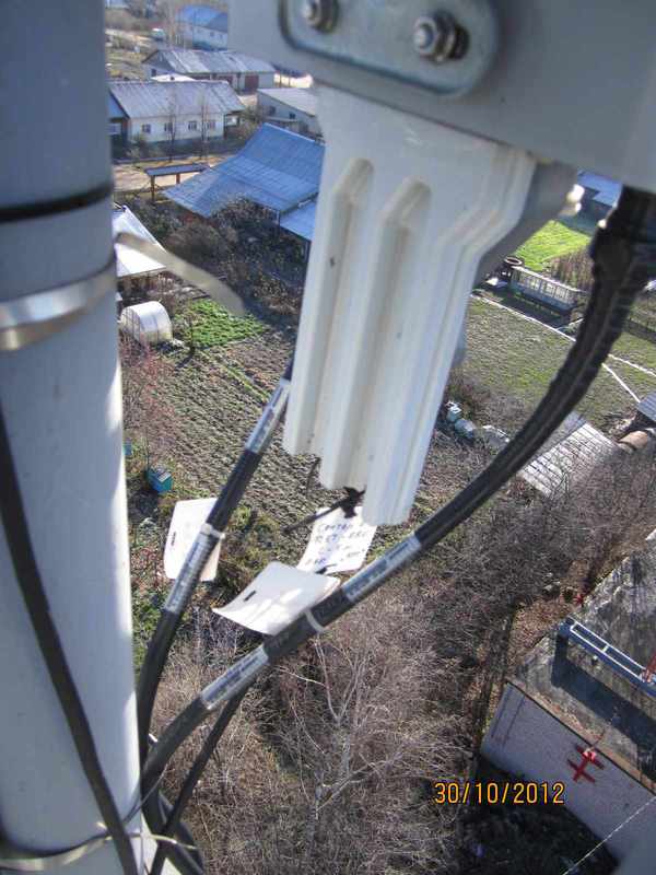
A pair of jumpers from the feeders to the antenna.
Marking of feeders using tags.
Grounding feeders.
Grounding points for feeders on a metal structure.
Tube with antenna and external PPC unit.
Marked antenna RRS.
RRL flight, visible hub tower in the distance.
Label on the outdoor PPC unit.
In the top photo, the leftmost connector is used to connect a voltmeter when adjusting (adjusting) the span, the voltage at this connector is proportional to the level of the received signal from the response relay. The next connector for connecting the ODU and IDU (outdoor unit & indoor unit) PPC is a coaxial IF cable (intermediate frequency). The connector is sealed against moisture in the cable. Extreme right point for block grounding.
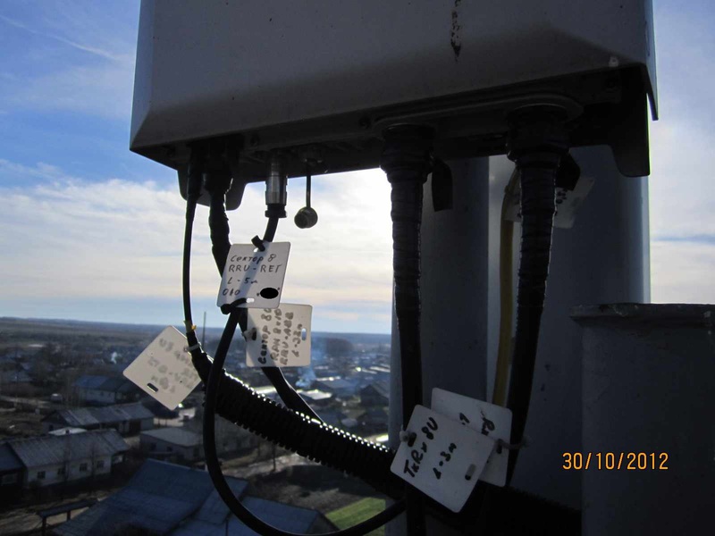
Labeling of cables PPC.
Actually fixture antenna RRS. Two long screws / studs are used for fine adjustment of the RRL span.
View of the site from above.
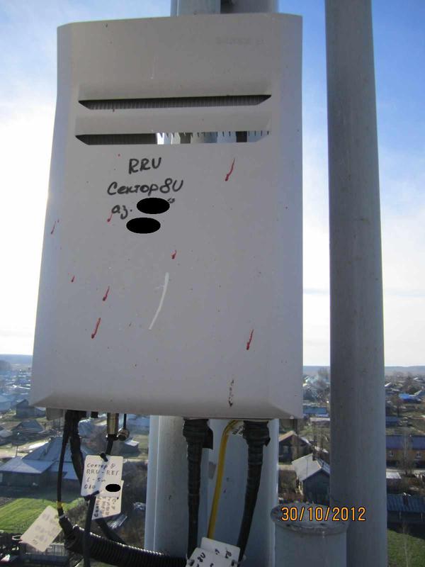
RRU - remote radio unit standard UMTS.
What is connected to the RRU? On the left, a thin optical cable comes in from the corrugations into the transmitter, inside which a conventional SFP module is installed. Next comes the power cable (also -48 V, DC). To the right is a thin cable for connecting to RET (Remote Electrical Tilt) - a device that controls the electric angle of the sector antenna. Then 2 jumpers to the antenna and a yellow-green ground cable.
It should be explained why antennas with cross-polarization are used that in GSM, that in UMTS. In fact, there are 2 antennas with different polarization (usually angles of +45 degrees and -45 degrees) in the case, so 2 feeders from the transmitters are connected. Thus, polarization diversity of the signal received from the subscriber is realized.
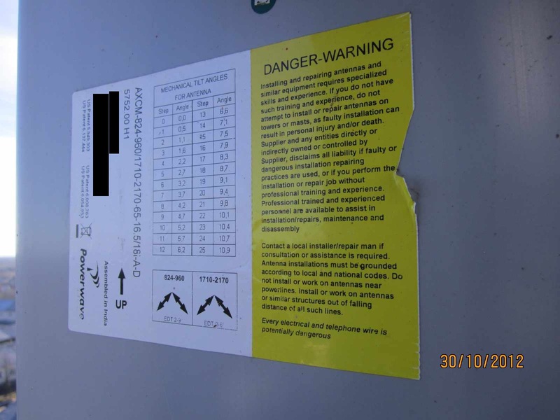
Label on UMTS antenna.
Ret behind.
RET from the front of the antenna.
View of the top of the hardware (30 m).
BS of competitors with a climatic case in which all necessary for work is established.
After the end of the work we close the hatch to the site from the "vandals".
Closing the site fencing ...
... we are loading into pepelats and going to rest.
I hope this small photo report will show you how the usual base station of mobile communication is built and how, approximately, everything is implemented in hardware. I apologize for the quality of the photo, the shooting was carried out in working order. The post was written for an invite to Habr with the hope of new interesting publications.
PS As a suggestion: “There is no disclosure of corporate information in the post!”
PPS Thank @FakeFactFelis for an invite.
Source: https://habr.com/ru/post/172093/
All Articles