How to increase the IQ of the network button without interfering with the operator’s brain
It would seem that nothing is easier than the network button! But sometimes you want something like that ... something else ... something like not everyone. And if everything else we are much, then the network button equalizes all. Jokes jokes, but sometimes the network button really delivers a lot of trouble. For example, when it needs to be placed on the front panel of the device, and the network wires are dragged through the entire body, filling it with a background of 50 Hertz. Or brutal flipping toggle switch does not fit into the design concept of the device. A situation may arise when the network button will lack "intelligence". For example, when pairing any device or an old Soviet measuring device with a computer. In this case, we can help out an electronic network button.

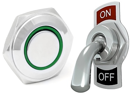
At the heart of the "electronic button" (Fig. 1), oddly enough, is the button - S1. The usual "mikrik", without switching (tee), without fixing, which can be comfortably placed on the front panel of the device, providing an elegant key. You can find similar pushbutton switches combined structurally with the indicator LED (Fig. 2) and different types of performance. For "printed" installation (Fig. 2.a), and more solid, anti-vandal (Fig. 2.b). The latter, among other things, a good design. In general, there is something to choose from.

But the most important element of the "electronic button" is the legendary NE555 timer. In our design, it performs the functions of a trigger, level comparator, and power switch to control the executive relay. Controls the dual-mode LED of the “button” status (on / bright, off / dim), and also performs a number of functions specific to the simple network button.
Now let's get in order. A level comparator, more precisely two comparators, are integrated into the timer itself with all the strapping circuits necessary for setting the response thresholds. Typical values of the levels of operation of the comparators are 1 / 3Upt for the comparator of the lower switching threshold and 2 / 3Upt for the comparator of the upper switching threshold. Each of the comparators controls the RS trigger, which is also integrated into the timer itself. The comparator triggered by the lower voltage level switches the built-in trigger to the Set state (set), and the comparator triggered by the upper level sets the trigger to the Reset state (reset). The output signal of the timer is fully consistent with the state of the internal RS trigger. So, in the Set state, the timer output is high, in the Reset state, low. The executive relay is controlled by the output driver cascade of the timer. The output current of this stage can reach 200 mA, which is quite enough to turn on a small relay. The high voltage level at the driver output is equal to the circuit supply voltage, minus 1.7 volts (typical value). Low, about 0.3 volts. It is worth remembering that the low voltage depends on the flowing current.
The brightness of the LED also controls the timer. For this purpose, an integrated into the microcircuit transistor is used, designed, in the original switching on, for discharging the time-sensitive capacitor (Discharging). In our case, it is used as another output of the open collector timer. In the Set state, the transistor is closed, and in the Reset state, by a signal of a logical unit from the inverse output RS of the trigger, the transistor is open.
In our scheme, this timer output can also perform another function — it can “inform” third-party devices that the button is in the “on” state. Even in our scheme, the reset timer input can be used. This input is intended not only for resetting the timer built-in RS trigger. If you keep this input in the zero state, the timer stops responding to external signals altogether. This property of the timer can be used if it is necessary to prohibit turning off the “button” by applying an external signal of a logical zero to this input.

Now let's see how this all works. Let's start with the moment when the supply voltage is applied to the “button” circuit. At this moment, logically, the “button” should be set to the “off” state, and in order for this to happen reliably, a capacitor C1 is provided in the circuit. Let's see how this happens. At the moment when the voltage is applied to the circuit, the voltage, at the medium point, of the internal voltage divider of the timer, consisting of resistors Ra, Rb and Rc, almost immediately reaches its typical values - 1 / 3Upit and 2 / 3Upit. As we learned above, switching the RS trigger timer to the Set state (it corresponds to the “off” state in our scheme) is the voltage value at the Trigger input of the timer, less than 1 / 3U power. The voltage to this input is supplied from the divider R1 and R2 and is 1 / 2Upit, which does not fulfill the conditions for switching the internal RS trigger to the Set state. How to be? The discrepancy ... - Yes, the discrepancy. It is for this purpose that the capacitor C1 serves, it delays the rise in voltage at the Trigger input. The front becomes flatter, and when the comparator's reference voltage is 1 / 3Up for a long time, the voltage at the Trigger input still stretches somewhere to its cherished 1 / 2Upit, and still much less than 1 / 3Upit. Thereby, conditions are created for the initial setting of the timer to the Set state, and the “buttons” to the “off” state. This point in time is designated as Self OFF (see Figure 3).
Now about the resistors R1 and R2. These two resistors form a voltage divider, which is fed to the inputs of the timer. This voltage is 1 / 2Up. Why exactly so much? This level is schematically shown (see Fig. 3) as the Middle (medium) level. The Set level and Reset level correspond to the switching levels of the timer comparators. That is, in the state of waiting for pressing the button, the signal level at the timer inputs occupies an intermediate value equidistant from the upper and lower levels of the triggering / switching of the timer. Besides the fact that it is necessary for the correct operation of the device, it is also advantageous in that the magnitude of the impulse noise induced in the wire with which the S1 button is connected can reach ± 2 Volts. That is, the wires can be quite long and even not shielded (although the screen should not be neglected).
The resistor R5 and the capacitor C3 perform the function of feedback and are elements of the formation of pulses. Feedback has a time constant of 1 second, which miraculously coincides with the “tau” of the RC circuit. This means that the button cannot be switched more than once per second. More can be done. How? Recalculate the time constant or just pick up the capacitor C3. Resistor R1 for these purposes is not suitable. By increasing the capacitor C3, this time can be increased, and reducing, respectively, reduced. These time intervals are designated as Relax ON and Relax OFF (see Fig. 3). In addition, after turning on the power plug into the outlet, the “button” cannot be “turned on” for another 1 second. This time on the graph (Fig. 3), denoted as Lost time (lost time).
Now, what are the impulses and where do they come from? Impulses are generated when you press a button. And each time is different. Pressing the S1 button when the “button is off” generates a pulse of positive polarity relative to the Middle level, and when you press S1 when the “button is on”, a negative impulse (see Fig. 3). This is due to the feedback consisting of a resistor R5 and a capacitor C3. Feedback, it is the reverse, to transfer to the input of the device part of the signal from the output of this device. In the “button off” state, the output of the device is high, as the internal RS trigger is in the Set state (we talked about this earlier). This means that the voltage on the capacitor C3 is (in steady state) of the order of 10 volts. This level is marked as Timer OUT Hi (Fig. 3). When the contacts of the button S1 are closed, the capacitor C3 begins to discharge on the resistor of divider R2, which leads to the appearance of a pulse on it with an amplitude of 4 volts, which is fed to the input of the timer. The timer will immediately respond by triggering the top level comparator and switching the RS trigger to the Reset state. At the output of the device, a low voltage level is established, and the capacitor C3 will continue its discharge, only not on the resistor R2, but on the output of the device through the resistor R5. After some time, the charge of the capacitor will be equal to the output voltage of the device, about 1 Volt. This level is marked on the graph as Timer OUT Lo (see Figure 3). Now if you close the contacts of button S1 again, it will be charged through resistor R1, which will lead to the formation of a voltage pulse on the resistor, only in this case reverse polarity relative to the level of Middle (see Fig. 3). The appearance of this pulse at the timer input will trigger the low level comparator and switch the internal RS trigger to the Set state. And our button will switch to the "off" state.
Capacitor C2 does not play a significant role. But, they say - it is necessary ... It is necessary - it means - it is necessary. It is blocking and protects against impulse noise. It is connected to the input of the Control timer, which is not used in our circuit.
Like any network button, our “electronic button” also has a group of powerful contacts. Only these are the contacts of the executive relay P1. As previously mentioned, the executive relay is controlled by a driver built into the timer. When the output voltage is high (10 volts) - the relay is off, and when low - the relay is turned on. How is it, how is it ... - And this is how it is ... See how the relay is turned on - between the power of the circuit and the timer output. This can be thought of as an inverted output of a logic element with a connected LED, when the output is zero — the LED is on, when the unit is not. And here, just at a high voltage level at the timer output, only two volts are applied to the relay winding, and this is not enough for it to pull its anchor. And at a low level at the output of the timer, the voltage on the relay coil will be 11 volts and it will work. When choosing a relay for the “button” scheme, the current for which the relay contacts are calculated should be taken into account. The winding resistance should not be less than 200 Ohms, the operating voltage should not exceed 12 Volts.
The indication of the status of the "electronic button" is carried out by the LED HL1. How can one LED display two states? A very simple - the brightness of the glow. For this purpose, the input of the Discharging timer is used, and in our device it is used as an additional timer output with an “open collector”. When our “button” is in the off state, the transistor inside the timer connected to this output is closed, and the output has high resistance. The current that “ignites” the LED flows through two resistors, R3 and R4, and this current is enough only for the glow of the LED in polnakakala. When the “button” is in the “on” state, the transistor is open, the input has low resistance and the resistor R4 is out of business, and most of the current flows through the open transistor. The total resistance in the circuit decreases, the current in the circuit increases, and the LED shines brightly, signaling that the “button” is on. If you need more illumination, then you can install two LEDs, and different colors. How to do this is shown in Fig. 3. At a high signal level, at the output of the timer, the HL1 LED will light, and at low HL2. The on state is probably more convenient to display with a green LED, and off it with a red one. Although it is possible and vice versa ...
The winding of the relay is shunted by a protective diode VD2, and it protects not the relay winding, but the timer output from this winding. The diode is connected in the opposite direction with respect to the poles of the power supply of the circuit, and most of the time is simply closed. It opens only when the relay is turned off. At this moment, the moment of current interruption, a voltage pulse arises on the winding of the relay, which at the given moment of time is more correctly considered as an inductance coil. If you give this impulse freedom of choice, then he will hasten to do things! For example, it strikes one of the transistors of the output timer driver. In order to prevent this from happening, this diode is installed. At the moment of the pulse, the diode opens, and the voltage pulse turns into a current pulse that flows through the circuit: winding - diode - winding. All are safe and sound, and the opinion of the impulse doesn’t bother anyone, do you know whether it’s already superfluous ...
Now about the power button. Logically, it should be individualized and appear as soon as the device is connected to the network. I used for this purpose a transformerless, or as they are also called - capacitor power supply. For low-power loads with low current consumption can be successfully applied. These blocks are simpler, since they do not have winding products, but they have a couple of serious flaws. There is no galvanic isolation from the primary network - this is the first, the second - have almost zero noise immunity. Therefore, when working with equipment powered by such units, you need to be very careful.
The most important element that underlies the idea of this kind of power supply is ohmic ballast, on which all the excess voltage of the power source connected to the circuit should fall. In our case, as a ballast, the capacitor C5 acts. Like a capacitor !? - And so ... As it is known from the course of school physics, in addition to the capacitor, capacitors also have resistance. Only not active - like ordinary resistors, and reactive. Active resistance manifests itself regardless of whether the current flows through it - alternating or constant. But the reactance, recognizes only alternating current, just the one that lives in a power outlet. Knowing the amount of current that the “button” consumes and the supply voltage for which it is designed, it is possible to calculate the resistance value, which must be installed in series, into the power supply circuit, from an AC mains voltage of 220 Volts. Well, since the magnitude of the reactance is directly related to the capacitance of the capacitor and the frequency of the alternating current, it is easy to calculate what capacitance the capacitor needs to be applied to extinguish the excess voltage at a given current. What horrible capacitor is not suitable here. Suitable domestic capacitors such as K73-17 or imported Klass X2 or Klass X1 for a working voltage of at least 400 volts.
So, with the main "Conder" figured out, let's see what else we have in the power supply. Parallel to the capacitor is a resistor R6. This is necessary to discharge the capacitor when the device is disconnected from the network. If you do not do this, then the plug-out can be very hot. A current limiting resistor R7 is installed in series with the capacitor and the diode bridge. Stop top stop ... - we already put a capacitor - is this not enough? - No, no ... just right ... And this resistor is used to limit the current when the device is turned on. If you do not put it, we risk losing a pair of diodes in a rectifier bridge, since according to the most "important" law of our life, the device will always be switched on to the network at the moment of the amplitude maximum of the mains voltage equal to 311 volts. The magnitude of the resistance of this resistor depends on the sensitivity of the diodes of the rectifier bridge to the maximum allowable, for them, current pulses. Knowing this parameter of the diode and the amplitude value of the voltage in the outlet you can estimate the value of the necessary resistance according to Ohm's law. It is less threatening to the VD2 Zener diode, since at the moment of switching it on it is shunted by a discharged capacitor C4. At the same time, in sum with the equivalent load resistance and the capacitance of the “quenching” capacitor, this resistor plays the role of a kind of network noise filter (albeit very frail, to about one kilohertz).
Diode bridge VD3-VD6, serves to rectify the alternating voltage, in a constant, pulsating voltage. Diodes can be replaced by 1N4007. Capacitor C4 to smooth these pulsations, and Zener diode VD2 to limit the voltage level on the capacitor and the output of the power supply. Yes, it is for limitation, about a full-fledged parametric stabilizer with a choice of the operation mode of the Zener diode, there can be no question here. But we have nothing to do with the stabilizer, the circuit works in a large voltage range and plus minus volts will not confuse it.
With the use of "buttons" I think there should be no difficulties. She can equip an existing device or use it in a new model. The inclusion scheme is very simple (see fig. 4).

Now about intelligence ... I don’t know how to increase the IQ of the network button without interfering with the operator’s brain. But when the "electronic" button - God himself commanded ... uh ... well, that is, I ... First, let's see why this is necessary. It may well happen that you will ever need to connect any device to your computer via LPT or COM interface or even USB. How will the computer determine, and have you forgotten to press the “network” button on the device before you begin data exchange? Or just at the time of data exchange, you gap, press the button and turn off the device connected to the computer? Data lost!Yes, and figs with them, the main thing is time, and time, as they say, is money, but everyone loves money, and they don’t like to lose ... yes ... In order to avoid such incidents, the “button” must be taught to inform the computer that it is on, and teach the "button" not to pay attention to the operator, that is, to you, for a while. Allow the computer to allow it to do the "button". These two possibilities are realized in the scheme shown in Fig. 5. Well, since in our “button” the power supply is used without galvanic isolation from the primary network, then with the realization of these possibilities, optocouplers cannot do.

An example implementation is shown in Fig. 6 for COM port, and in fig. 7 for LPT port. And it is given solely as an example of using the “specific functions” of the “button”, but how it will be implemented in your case ... especially since these two “old men” scare young people with only one of their appearance ... and FTDI and others have long been mastered V-USB ...

Let's start with the first - “to report that everything is included.” In order to realize this function, you will have to sacrifice the indication on the LED HL1 and use the display scheme shown in Fig. 5. And to the output of the DIS timer (pin 7), about which much has already been said, connect the LED of the optocoupler U2. But you can do without victims, then, the display remains the same (as in Fig. 1), and the LED of the optocoupler U2 migrates to the HL1 LED (see Fig. 5). The photodiode of the optocoupler U2, together with the pull-up resistor R19, is connected to the required port line (in my case it was the RI line - call indicator). The voltage to which the line is pulled up in a free state should be taken from one of the port lines set programmatically to the unit (since in my case the standard RS232 protocol was implemented,this was the DTR line - readiness output). With the “button on”, the RI line will be pressed to the potential zero SG. With the “off” state, the port line will be pulled to the potential of the logical unit. This is all said for the COM port, but with LPT everything is much simpler and you will not need to set anything in advance there. True full isolation of the device and the computer will not work, but the scheme of the "button" will be reliably isolated by power, with the rest of the device in which it will be applied.but the “button” scheme will be reliably untied on the power supply, with the rest of the device scheme in which it will be applied.but the “button” scheme will be reliably untied on the power supply, with the rest of the device scheme in which it will be applied.

Now, about - "pay no attention to the operator, that is, to you." Somewhere above, we recalled one of the timer inputs called Reset. It was not by chance. It is precisely this input that is used to implement this “button” function. For this, to the Reset input (pin 4), it is necessary to connect the photodiode of the optocoupler U1, through the current-limiting resistor R3 (see Fig. 5). In this case, this resistor will also be a pull-up resistor for the reset input of the timer. When the photodiode of the optocoupler is not illuminated, the resistance of the photodiode is high and a high logic level will be established at the input Reset just through this resistor. Now, after all the innovations, in order to prohibit the “button” to react to thoughtless presses, the input of the optocoupler must be energized. Voltage "logical unit",while not forgetting to limit the current of the optocoupler LED resistor R21. At the same time, the reset input of the timer will be pressed to the ground, and the timer will stop responding to external signals. In addition, using this input button can be forced to turn on the signal from the computer. Such here, a kind of Master ON.
Well, you always have to turn it off manually - with your finger ...
')
Source: https://habr.com/ru/post/171719/
All Articles