Cyber invitation to a wedding or how to effectively destroy patterns
On Habré already wrote a lot about home-made electronic devices of different caliber. What I want to tell you about is not to be put on a par with the “smart home” or the production of wooden mice. Surely, those who are just starting to have fun with DIY and think about where to start will find something useful for themselves. I hope this post will once again convince beginners that any, even the strangest, at first glance, idea is good for our business.
It all started with the fact that one day I decided to marry! Statement, preparation for the holiday, all things. But the task: to make original wedding invitations. Signed pieces of cardboard did not want to. Soul requested hardcore handmade, far from the traditional wedding patterns. And so on my “and in general, you can make electronic devices”, the bride said: “Cool! Come on! ”
By that time, my experience was about soldering Freedouin from a set of parts and ritual blinking with an LED. I thought with horror that I had to collect not one and not two, but 33 copies, beforehand said goodbye to the upcoming summer - and rushed ...
')
February. Wedding in August, but I already thought that I did not have time. Because, the devil knows where and what will go wrong. However, a plan gradually began to emerge: to blind the LCD screen, the battery, the button and some controller into one piece, so that at the touch of a button the device would display a message on the screen in rows.
The “Invitation” genre immediately dictated its additional requirements. It was important that the battery was not spent all for one or two shows and that the messages on all copies were different. In addition (and the bride implored me hourly), I wanted the result of my experiments to look like an artisanal, but product. That is, did not fall apart in his hands and did not spread wide in all directions of the loop of wires.
Picked up in the catalog of the nearest store of radio components, first took one for testing. According to the characteristics of the following: LCD, text, Russian letters, 1 line of 16 characters, with no backlight. WH1601A-NGG-CT ( datasheet ) is called, it costs more than a hundred rubles. The successful screen turned out to be a wave, later I bought them a whole box:

The controller picked up from the Atmel catalog (on the Atmel website, click on the MCU Selector). Atmel, because with Arduin I already had a little experience, and on easyelectronics there is an excellent course on AVR controllers . I was looking for such
ATTiny 2313A-PU ( Datashit ) is out.
Screen needed 5V power, so after some research I decided to use a pair of CR2016 batteries stacked in a stack in the holder for the CR2032.
Strangely enough, it turned out that it’s better to buy small things (resistors, capacitors, etc.) not in St. Petersburg, but to order from under Yoshkar-Ola (ekits.ru shop). Found all at normal prices.
I mastered the screen: I soldered wires to it, experimented from Arduin, I got him to write letters in turn with given pauses. I did not use libraries, I wanted everything myself. This is the code that turned out.
Everything was ready to work on the prototype.
March, April. The long period of writing firmware in assembler (deliberately not in C, in order to better feel the architecture), drawing and layout of the scheme. Showed the bride. “Come on,” she says to me, “it will also flash with lights.” In the process, I had to build in “more light bulbs”: I added two pairs of LEDs and work with interruptions, the wiring was a bit more complicated. (LEDs ordered all the same, from Yoshkar-Ola). The scheme as a result came this:

For beginners like me, explanations to the scheme:
But this firmware .
The layout for the first time came out difficult, so it is likely that I broke some canons. I had to get along with a bunch of conditions:
As a result, I managed with two jumpers, they are blue on the diagram:

I collected everything on a breadboard, debugged it for a long time, I got it to work ... Yes, I stitched it with Arduina according to the scheme chewed here. The circuit requires connecting the reset with power through a resistor: I hung the resistor right into the wire.
And yes, it was important that each device had a personalized text (invitation is the same!). The text was stored in the firmware in the form of a dump (“.db 0xa2, 0xa3 ...”). And the coding table at the screen has its own and with features. For example, it saves and contains only those Cyrillic letters for which there is no equivalent in the Latin alphabet. For convenient conversion, I made a utility on java .
How long, shortly by May did I have a working device, but on a breadboard. Power worked both from USB (through Arduin and piercing wiring), and from batteries. It looked like this:
In the video, I start the process by clicking on the board - this is because I mistakenly soldered the button on the other side. eight)
I didn’t do a programming connector on the final board. Just inserted the next microcircuit into the cot on the breadboard, sewed it and soldered it into the board. Inflexible but saves holes and components. And time, of course.
It was May. I started making the first copy. I will not paint LUT and etching, the DiHALT manuals have all been read. I will tell only about the individual features and differences from the manual.
It turned out like this. In the video, however, while without screws.
That's all. The devices were ready.

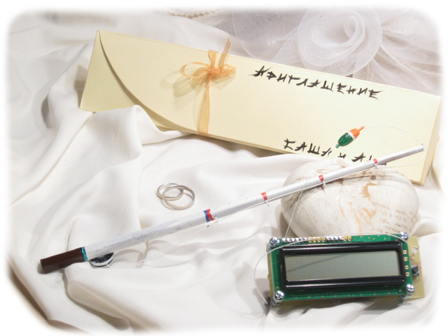
It remained to supplement the device with something that would make it even more like an invitation. This task was handled perfectly by the bride, who invented hanging the device on a small home-made fishing rod (if it flashes with lights, then why not with a fishing rod).
Of course, as it should be, they wrote the instruction manual for the device and packed it into self-made painted boxes. When you get everything, looks like this:

In general, the effect is achieved! The guests are delighted, the wedding was a success, we have - plus-a lot of experience and a desire to continue the experiments ...
So the idea
It all started with the fact that one day I decided to marry! Statement, preparation for the holiday, all things. But the task: to make original wedding invitations. Signed pieces of cardboard did not want to. Soul requested hardcore handmade, far from the traditional wedding patterns. And so on my “and in general, you can make electronic devices”, the bride said: “Cool! Come on! ”
By that time, my experience was about soldering Freedouin from a set of parts and ritual blinking with an LED. I thought with horror that I had to collect not one and not two, but 33 copies, beforehand said goodbye to the upcoming summer - and rushed ...
')
February. Wedding in August, but I already thought that I did not have time. Because, the devil knows where and what will go wrong. However, a plan gradually began to emerge: to blind the LCD screen, the battery, the button and some controller into one piece, so that at the touch of a button the device would display a message on the screen in rows.
Component selection
The “Invitation” genre immediately dictated its additional requirements. It was important that the battery was not spent all for one or two shows and that the messages on all copies were different. In addition (and the bride implored me hourly), I wanted the result of my experiments to look like an artisanal, but product. That is, did not fall apart in his hands and did not spread wide in all directions of the loop of wires.
Screen
Picked up in the catalog of the nearest store of radio components, first took one for testing. According to the characteristics of the following: LCD, text, Russian letters, 1 line of 16 characters, with no backlight. WH1601A-NGG-CT ( datasheet ) is called, it costs more than a hundred rubles. The successful screen turned out to be a wave, later I bought them a whole box:
Controller
The controller picked up from the Atmel catalog (on the Atmel website, click on the MCU Selector). Atmel, because with Arduin I already had a little experience, and on easyelectronics there is an excellent course on AVR controllers . I was looking for such
- to have enough legs, but was as little as possible
- so that the DIP-case (SMD I have not yet soldered and did not want to risk)
- so that power consumption can be small
- and that in the nearest store was available.
ATTiny 2313A-PU ( Datashit ) is out.
Battery
Screen needed 5V power, so after some research I decided to use a pair of CR2016 batteries stacked in a stack in the holder for the CR2032.
Any other
Strangely enough, it turned out that it’s better to buy small things (resistors, capacitors, etc.) not in St. Petersburg, but to order from under Yoshkar-Ola (ekits.ru shop). Found all at normal prices.
Prototype
I mastered the screen: I soldered wires to it, experimented from Arduin, I got him to write letters in turn with given pauses. I did not use libraries, I wanted everything myself. This is the code that turned out.
Everything was ready to work on the prototype.
March, April. The long period of writing firmware in assembler (deliberately not in C, in order to better feel the architecture), drawing and layout of the scheme. Showed the bride. “Come on,” she says to me, “it will also flash with lights.” In the process, I had to build in “more light bulbs”: I added two pairs of LEDs and work with interruptions, the wiring was a bit more complicated. (LEDs ordered all the same, from Yoshkar-Ola). The scheme as a result came this:
For beginners like me, explanations to the scheme:
Explanation of the scheme
In the middle of the controller, on the right screen. The seven wires from the controller to the small screen are three controllers and a four-bit data bus. All on datasheet. The screen does not feed directly, but from the leg of PD2 (V-LCD contact), this is because the device does not work most of the time, the controller goes to sleep, and the battery also does not waste battery power. There is also a VO-LCD, which is fed to the VO contact of the screen. According to the datasheet, there must be some voltage greater than zero, but less than VCC, the screen contrast is regulated by this voltage. Datashit offers to shove a rheostat there and adjust on the go. But not in every board rheostat shove! So I picked up the voltage experimentally and built a voltage divider to get it. This is the design of the two resistors below. It is also drawn below that the power supply is initially taken from the battery and that a capacitor is inserted in the power supply for protection, for example, from chatter when inserting fresh batteries. Well, actually that's all. There is also a reset button and four LEDs, which are included in pairs.
But this firmware .
The layout for the first time came out difficult, so it is likely that I broke some canons. I had to get along with a bunch of conditions:
- The board in size should have been a little more than the screen, so that it was convenient to press the start button.
- Connector and mounting holes - correspond to the connector and the holes on the screen board. (I then connected the holes with screws).
- Light-emitting diodes (on a design idea) - by all means to look in different directions.
As a result, I managed with two jumpers, they are blue on the diagram:
I collected everything on a breadboard, debugged it for a long time, I got it to work ... Yes, I stitched it with Arduina according to the scheme chewed here. The circuit requires connecting the reset with power through a resistor: I hung the resistor right into the wire.
And yes, it was important that each device had a personalized text (invitation is the same!). The text was stored in the firmware in the form of a dump (“.db 0xa2, 0xa3 ...”). And the coding table at the screen has its own and with features. For example, it saves and contains only those Cyrillic letters for which there is no equivalent in the Latin alphabet. For convenient conversion, I made a utility on java .
How long, shortly by May did I have a working device, but on a breadboard. Power worked both from USB (through Arduin and piercing wiring), and from batteries. It looked like this:
In the video, I start the process by clicking on the board - this is because I mistakenly soldered the button on the other side. eight)
I didn’t do a programming connector on the final board. Just inserted the next microcircuit into the cot on the breadboard, sewed it and soldered it into the board. Inflexible but saves holes and components. And time, of course.
Production
It was May. I started making the first copy. I will not paint LUT and etching, the DiHALT manuals have all been read. I will tell only about the individual features and differences from the manual.
- Pickled in a mixture of copper sulfate and salt. It is less caustic and the ingredients lie in the nearest building supermarket.
- Drilled a drill in 1mm for metal (less in that supermarket was not) and a drill, this, full-size. The hand was hard enough not to break the drill and do not lubricate the hole. A screwdriver was, though easier, but too slow. By the way, the recommendation that dust should be avoided is absolutely true! It is very small, white and almost invisible, if not poured into a handful. But if you are in the air, your throat is scary.
- At first he tugged, and then he drilled, although they recommend everywhere the opposite. But it is also easier! The rim of the hole becomes thicker and at the beginning of drilling additionally corrects the sight.
- I did it in batches - so much faster. That is, a dozen boards go through the first stage, then the second, and so on. It turns out fewer context switches, fewer instrument shifts and, accordingly, faster work. The steps are:
- Cut a piece of board and shake
- Smooth a piece of paper with a picture and wash it.
- Etch board
- Buzz tracks
- Drill holes
- Solder everything except the controller
- Insert the controller in the layout and flash
- Solder the controller
- Connect with screws
It turned out like this. In the video, however, while without screws.
That's all. The devices were ready.
Finishing touches
It remained to supplement the device with something that would make it even more like an invitation. This task was handled perfectly by the bride, who invented hanging the device on a small home-made fishing rod (if it flashes with lights, then why not with a fishing rod).
Of course, as it should be, they wrote the instruction manual for the device and packed it into self-made painted boxes. When you get everything, looks like this:
And the instruction that is visible in the photo, like this
In general, the effect is achieved! The guests are delighted, the wedding was a success, we have - plus-a lot of experience and a desire to continue the experiments ...
Source: https://habr.com/ru/post/171633/
All Articles