Wireless communications "smart home"
When the beginner (or continuing) “radio amateurs” played with the LEDs and were tired of turning the servos into different positions, some of them begin to apply their knowledge to the ordinary household sphere.
As a rule, this application is in two areas - a car or a house.
“Tyunit” cars are somehow not interesting to me personally, but to make your own housing a little bit “smarter” and more comfortable is a worthy choice.
The photo above shows a working prototype of the “Control Panel” of my “smart” home.
The choice of wireless modules was quite spontaneous, but after several months of operation, it was quite justified.
Cheap 2.4GHz nRF24L01 + transceivers were purchased:

According to the characteristics, it is stated that the range is up to 100m (in direct line of sight) and the data transfer rate is up to 2Mbps. You can use any of the 126 available frequency channels. Very worthy for such a "crumbs."
Just in case for the most "critical" modules there were "enhanced" versions :

These modules are fully compatible with "conventional", but additionally equipped with a power amplifier and an external antenna.
Modules connect to MK via SPI.
The peculiarity of the modules is that they need 3.3V for power (i.e. they need to provide individual power if the rest of the circuit is powered, for example, from 5V). The good news is that these RFs are tolerant to 5B signals (no level matching scheme is required).
And it seems like everything works and everything is fine, but somehow it is not very convenient - only via SMS, and it was rather difficult to implement new features. The control of execution was carried out either by another SMS with a request for the current value of the “sensor” or by looking into the video surveillance system (to see, for example, the switched on light).
When working with modules, one had to keep in front of him a “piece of paper”, where it was fixed, as the name of a particular sensor, the number of its parameters, the purpose of each of the parameters.
The format of the structure for data transmission was not optimal (for my case). This version of the format does not even want to bring.
It is clear that it is necessary to somehow modify (prerequisite # 1).
Naturally, there was a desire to receive information and manage more via LAN. An iBoard shawl was purchased (atmega328, LAN based on Wiznet W5100, interface for nrf24l01, SD, a bunch of analog pins, etc.):

And everything seems to be all as on gBoard, but it turned out that the wireless module is not completely divorced as expected. Hardware SPI in this board is used for LAN and SD, but for the wireless module it was proposed to implement this interface independently. This was most likely done so that it was possible to work “simultaneously” with both LAN and RF.
The Mirf library on this board with this switching module refused to work categorically. Writing my library to interact with nrf24l01 was not at all my plans.
Obviously, something needs to be done, otherwise a good fee will go “on the table” until better times (prerequisite # 2).
The wonderful library RF24 (by maniacbug , Seattle, USA) and even more wonderful fork iBoardRF24 made by Andrey Karpov (Kiev, Ukraine) were discovered .
Libraries did a great job on all available devices (test cases), but devices with different libraries (Mirf and RF24) cannot communicate with each other (premise # 3).
It became obvious that the very moment came when it was necessary to redo everything.
Having already gained considerable experience, I took all the good things from the structure of the transmitted data and took into account the existing shortcomings and came to the conclusion that it is better to use the following structure of the “packet” of data:
From the comments almost everywhere it is clear which parameter is used for what. What is not clear will be explained below.
Inside each “sensor” it is necessary to have structures for the parameters:
The structure has three parameters. Well, with “value” everything is clear, the “Note” field is used to give some kind of intelligible (but brief) explanation of what kind of a sensor it is and, possibly, a unit of measurement.
Status wound up more for control and possible flexibility in the future.
Now it is used, for example, if it was not possible for some reason to read data from some sensor, then the system can safely handle this situation and transmit 0, denoting the problem.
It is seen that the second structure completely repeats the “end” of the structure of the transmitted packet.
The format of the transmitted “packet” is absolutely identical for both “master” (the one who sends commands and collects data) and the “slave” (the one who receives commands and reports on the work done). Moreover, with this approach, master and slave are quite conventional symbols. Modules really communicate on an equal footing and requests with answers can go both ways.
Now you can begin to describe a specific module. Take some hypothetical module with 3 parameters. It will be encoded as follows:
Please note that in spite of the fact that parameters 3, a structure of 4 elements is declared. For myself, I accepted that in the “zero” element I will always encode information about the “module” itself - the number of its sensors, give information that the sensor can accept commands or it only has a “sensor” and a text description of the sensor.
With the data figured out, go to the functions:
This is how the function with which the command is sent is declared.
Returns "true" if the correct answer came, or "false" if it failed.
Input parameters: from which module the command goes, to which module, the command (read or set), which parameter, value, comment and link to the structure for the answer.
The “comment” parameter here is more a “bookmark for the future” so that, for example, you can change the names of the modules and the names of the parameters.
The result of the function is determined by the following rules:
Thus, to find out the value of the first sensor from our hypothetical sensor, it suffices to call the function on the master (let its SID be 900) as follows:
Accordingly, on the “receiving” side in the main loop there should be something like this:
The doCommand function can be something like this:
The sendSlaveMessage function is almost the same as sendMasterMessage, but does not check the correctness of the response after it has sent data and contains fewer input parameters — the function accepts the input of the identifier of the module to which the parameter identifier responds, the information about which needs to be sent.
The system already knows the rest of the required data for the composition of the sending package (remember, there are still required fields — the identifier of the module that sends the data at the moment, the command (in this case it will be 0, because we just send the current value )).
Thus, the logic of the work is simple:
The code for gBoard was also rewritten accordingly and now the interaction via SMS looks something like this (part of the screenshot from my phone):

The first SMS I request the temperature of the eastern sensor from the “weather” module, the second SMS - I set the desired temperature of the “forced” thermostat. In response, I get a measured value or an answer about a successfully set value (at the end of the message there is “OK!”).
It is clearly seen that the SMS includes the data necessary to form a complete request for a specific module. I agree that the format of outgoing messages is not too simple, then it will be possible to rewrite it into something more “human-readable”.
At this “address” data exchange describe finish.
But there are other modules in the home system that are primitive “sensors”. A typical example of such a module is a temperature and humidity sensor, which may be battery operated and it must protect its resources and “sleep soundly” and wake up solely in order to quickly send information about your condition and “sleep” again.
For him, the "request-response" mode is not suitable (you will have to keep at least the RF module in a "waking" state, which will adversely affect the battery life).
Then I thought that it was possible to arrange “flood” on the air: the sensors can send their parameter values (all or only some of them on a regular basis) for all (then the To parameter (to whom) takes the value 0 (i.e. " all ")).
It turns out a kind of "multicast" - the module woke up, gave its status to the air (and it does not matter to him if someone heard it or not) and fell asleep again.
Almost all the modules that work "addressfully" added the "flood" mode, so that they also regularly broadcast their status (for the logging system).
And now it remains only to collect the data together. This is where the iBoard board came in handy (I’ll bring her photo again, with the RF module already installed):

One simple, but very important function is assigned to this module - to listen to “flood” and send data (POST method) to a web server. A module on iBoard doesn't know anything at all about the number and "composition" of transmitting modules - it listens to everything.
In the data packet for the web server, the “key” is transmitted (so that the server understands that it is “its own”) and the full received packet (I repeat once again that the following key data comes in the packet: module SID, parameter ID, value of this parameter, comment (parameter name and / or unit of measurement)).
If in the received ParamID package it is equal to zero, then in the value of the parameter we have the number of “sensors” in the module, and in the “comments” - the name of the module.
On the web server, in automatic mode, records are formed in 2 labels: sensor_list and sensor_value (from the names, I think, everything is clear).
The applied approach allows you to add modules to the system completely painlessly and not to correct the code for iBoard - the new values will get to the database according to a well-established pattern.
As a web server, I used what was “at hand” (Synology DS411 + II) - a web server with php and mySQL was raised in a couple of clicks. If there is nothing suitable “at hand” and you don’t want to keep the computer on for the sake of it - you can use third-party hosting, buy something like this (nice and useful) or, for example, cosm.com service
Depending on the choice of “storage”, the code for the MC with a LAN module will change minimally (cosm.com has its own library for arduinka and a convenient debugging mode — it's very easy to use).
The data collected (and in the case of using cosm.com - already displayed on the graphs).
In my project, I used Google Charts for display. It turns out like this (weather parameters only):

Specially bring a screenshot, but I do not give a link to the page - NAS, I think, will not withstand the load from Habr.
The data from the sensors are “noisy”, we should use the Kalman filter , but my hands have not reached it yet.
Actually, with the collection and display of data - also finished.
It remains to implement control via LAN (and this is still not done and, if interested, will be the topic of another post (although the basic principles are already voiced - how to do it is clear, you just need to "sit down and write")).
You may ask: "What is the picture with which the post started?"
And this is another board for rapid prototyping - iBoardPro (built already on mega2560, LAN, RTC, SD, RF-interface, 40-pin connector for connecting TFT displays with touchscreen and other "buns"):

The photo clearly shows the TFT 2.4 "320 * 240 display with a resistive touchscreen ITDB02-2.4E . It looks good, but it's too small for work with your fingers, and I would like more texts (I will look towards 5 or even 7-inch displays).
Using the principles described above, this board implements (but still appends) a “control module” to which data from the desired sensors is output and it is possible to control those devices that support it.
A short video showing the current work of the prototype:
The logic of work is as follows:
The “control buttons” on the screen have “feedback”: i.e. after the inclusion of a specific mode - it is displayed in the appropriate color. If something has already been included earlier, then when you go to the control screen, it will be immediately visible.
Each "press" on the button generates a call to the sendMasterMessage function with the appropriate parameters and receiving a response from a specific sensor (it is from this data that the buttons are repainted or the value changes, as is evident for the set temperature of the "forced" thermostat).
It can be seen that there is a certain delay in “repainting” the button and changing the parameter - this is due not only to the slowness of the MC when rendering, but also because it takes time to send a request and receive a response (sometimes the “request-response” process goes more than once - master able to repeat his "order", if not wait for the expected response).
The “purple” screen is planned to be used to display data about the state of the system: current IP address, start time, last synchronization time via NTP, last “connection” times (or “auditions”) with specific sensors, etc.
Perhaps that today is all that I wanted to tell (and so it happened a long time).
Sorry for the quality of the photo - I shot the phone on themicrowave .
PS “Zhelezki” acquired in this store (of course, I overpaid, but did not want to wait for a long, long time from China, during which time I managed to order and receive several parcels from the NSC). Closer and faster nowhere found.
PPS Yes, all these “glands” (well, except perhaps for a display) can be assembled at home, but that was not the goal.
As a rule, this application is in two areas - a car or a house.
“Tyunit” cars are somehow not interesting to me personally, but to make your own housing a little bit “smarter” and more comfortable is a worthy choice.
The photo above shows a working prototype of the “Control Panel” of my “smart” home.
Lyrical digression # 1: How it all began (you can skip it, but someone may be useful).
The initial philosophy of my “smart home” was as follows: each device created was made to achieve a specific goal and it should work independently .
So at home there appeared devices like:
The house uses not only home-made, but also purchased "smart" devices. One of these very successful devices is the chronothermostat:

The thermostat operates in two modes:
Everything is extremely convenient, the individual schedule of the “night” and “day” mode is set up, both temperatures are set. "Night" mode for myself is configured so that it turns on both at night and during the day, when no one is at home.
But since my working day is not normalized, after several early returns it turned out that it was somehow not very pleasant to return to a cool house from a cold day .
')
From that moment, the epic began with wireless communications (it was possible, of course, to entangle the whole house with a “twisted pair”, but this is not our method).
The initial philosophy of my “smart home” was as follows: each device created was made to achieve a specific goal and it should work independently .
So at home there appeared devices like:
- IR lighting control in the living room (the original lamp was with radio control, but I wanted to control it from the universal IR remote control).
- Weather Station .
- Power monitoring device and others.
The house uses not only home-made, but also purchased "smart" devices. One of these very successful devices is the chronothermostat:
The thermostat operates in two modes:
- "Night" - the temperature is lower so that it is more comfortable to sleep (and save gas).
- "Daytime" - the temperature is higher and more comfortable for wakefulness.
Everything is extremely convenient, the individual schedule of the “night” and “day” mode is set up, both temperatures are set. "Night" mode for myself is configured so that it turns on both at night and during the day, when no one is at home.
But since my working day is not normalized, after several early returns it turned out that it was somehow not very pleasant to return to a cool house from a cold day .
')
From that moment, the epic began with wireless communications (it was possible, of course, to entangle the whole house with a “twisted pair”, but this is not our method).
The choice of wireless modules was quite spontaneous, but after several months of operation, it was quite justified.
Cheap 2.4GHz nRF24L01 + transceivers were purchased:
According to the characteristics, it is stated that the range is up to 100m (in direct line of sight) and the data transfer rate is up to 2Mbps. You can use any of the 126 available frequency channels. Very worthy for such a "crumbs."
Just in case for the most "critical" modules there were "enhanced" versions :
These modules are fully compatible with "conventional", but additionally equipped with a power amplifier and an external antenna.
By the way, they are still doing nothing so far - it turned out that in my case there are enough “ordinary” modules.
Modules connect to MK via SPI.
The peculiarity of the modules is that they need 3.3V for power (i.e. they need to provide individual power if the rest of the circuit is powered, for example, from 5V). The good news is that these RFs are tolerant to 5B signals (no level matching scheme is required).
Lyrical digression # 2: First experiences.
Initially, the Mirf library was used to work with wireless modules.
To eliminate the "cool house" problem (see Lyrical digression # 1 ), a "forced" thermostat was created.
The module is a small box that connects between the gas boiler and the chronothermostat:

The module is equipped with 2 relyushki that provide the necessary switching, its own temperature sensor (DS18B20) and 3 LEDs to indicate the operating mode.
The logic is simple: if the “forced” thermostat has an automatic mode of operation selected - it pretends to be a “piece of cable” and does not affect the interaction between the boiler and the chronothermostat. But if he was transferred to the “manual” mode of operation, the chronothermostat is disconnected from the boiler and no longer participates in the work, the “forced” thermostat becomes responsible for the temperature of the house.
The module has 2 parameters:
In addition, this module is a “sensor” of temperature, a monitoring function was added a bit later, which shows whether “the gas boiler is currently allowed to heat”.
Thus, the first device is created that can transmit data about its state and receive commands.
But in order to manage it, you need at least one more.
The choice fell on the gBoard board (atmega328, sim900 based gsm, interface for nrf24l01 (using hardware SPI), SD, a bunch of analog pins, etc.):

The SIM card slot is located on the back of the board (I didn’t take pictures - there’s nothing else interesting there).
Again, using the same library for nrf24l01 (Mirf), a sketch was written.
Now it is possible via SMS to request the current temperature of the house, set the desired temperature and transfer the "forced" thermostat from one mode to another.
The problem of “cool home” was decided: just going to the side of the house to send an SMS with the meaning “I want a warm home for arrival”.
Similarly, the module for IR light control was equipped with a wireless module and also became controlled via SMS (again, this module became another “sensor” in the system - temperature / humidity / light condition).
After a while, almost all the “crafts” acquired a wireless interface and at least became “sensors”, and at the maximum, executive devices with remote control capabilities.
At the same time, all devices remained true to the basic principle indicated above: each device created was made to achieve a specific goal and it should work independently .
To eliminate the "cool house" problem (see Lyrical digression # 1 ), a "forced" thermostat was created.
The module is a small box that connects between the gas boiler and the chronothermostat:
The module is equipped with 2 relyushki that provide the necessary switching, its own temperature sensor (DS18B20) and 3 LEDs to indicate the operating mode.
The logic is simple: if the “forced” thermostat has an automatic mode of operation selected - it pretends to be a “piece of cable” and does not affect the interaction between the boiler and the chronothermostat. But if he was transferred to the “manual” mode of operation, the chronothermostat is disconnected from the boiler and no longer participates in the work, the “forced” thermostat becomes responsible for the temperature of the house.
The module has 2 parameters:
- Mode of operation (0 - auto, 1 - manual).
- Set temperature
In addition, this module is a “sensor” of temperature, a monitoring function was added a bit later, which shows whether “the gas boiler is currently allowed to heat”.
Thus, the first device is created that can transmit data about its state and receive commands.
But in order to manage it, you need at least one more.
The choice fell on the gBoard board (atmega328, sim900 based gsm, interface for nrf24l01 (using hardware SPI), SD, a bunch of analog pins, etc.):
The SIM card slot is located on the back of the board (I didn’t take pictures - there’s nothing else interesting there).
Again, using the same library for nrf24l01 (Mirf), a sketch was written.
Now it is possible via SMS to request the current temperature of the house, set the desired temperature and transfer the "forced" thermostat from one mode to another.
The problem of “cool home” was decided: just going to the side of the house to send an SMS with the meaning “I want a warm home for arrival”.
Similarly, the module for IR light control was equipped with a wireless module and also became controlled via SMS (again, this module became another “sensor” in the system - temperature / humidity / light condition).
After a while, almost all the “crafts” acquired a wireless interface and at least became “sensors”, and at the maximum, executive devices with remote control capabilities.
At the same time, all devices remained true to the basic principle indicated above: each device created was made to achieve a specific goal and it should work independently .
And it seems like everything works and everything is fine, but somehow it is not very convenient - only via SMS, and it was rather difficult to implement new features. The control of execution was carried out either by another SMS with a request for the current value of the “sensor” or by looking into the video surveillance system (to see, for example, the switched on light).
When working with modules, one had to keep in front of him a “piece of paper”, where it was fixed, as the name of a particular sensor, the number of its parameters, the purpose of each of the parameters.
The format of the structure for data transmission was not optimal (for my case). This version of the format does not even want to bring.
It is clear that it is necessary to somehow modify (prerequisite # 1).
Naturally, there was a desire to receive information and manage more via LAN. An iBoard shawl was purchased (atmega328, LAN based on Wiznet W5100, interface for nrf24l01, SD, a bunch of analog pins, etc.):
And everything seems to be all as on gBoard, but it turned out that the wireless module is not completely divorced as expected. Hardware SPI in this board is used for LAN and SD, but for the wireless module it was proposed to implement this interface independently. This was most likely done so that it was possible to work “simultaneously” with both LAN and RF.
The Mirf library on this board with this switching module refused to work categorically. Writing my library to interact with nrf24l01 was not at all my plans.
Obviously, something needs to be done, otherwise a good fee will go “on the table” until better times (prerequisite # 2).
The wonderful library RF24 (by maniacbug , Seattle, USA) and even more wonderful fork iBoardRF24 made by Andrey Karpov (Kiev, Ukraine) were discovered .
Libraries did a great job on all available devices (test cases), but devices with different libraries (Mirf and RF24) cannot communicate with each other (premise # 3).
It became obvious that the very moment came when it was necessary to redo everything.
Below are pieces of code (Arduino IDE) to illustrate the current solution. I do not give a full listing to leave room for creativity.
Having already gained considerable experience, I took all the good things from the structure of the transmitted data and took into account the existing shortcomings and came to the conclusion that it is better to use the following structure of the “packet” of data:
// typedef struct{ int SensorID; // int CommandTo; // ... int Command; // // 0 - // 1 - // 2 - int ParamID; // float ParamValue; // boolean Status; // 0 - , 1 - char Comment[16]; // } Message; From the comments almost everywhere it is clear which parameter is used for what. What is not clear will be explained below.
Inside each “sensor” it is necessary to have structures for the parameters:
// typedef struct{ float Value; // boolean Status; // - 0- (false), 1- (true) char Note[16]; // } Parameter; The structure has three parameters. Well, with “value” everything is clear, the “Note” field is used to give some kind of intelligible (but brief) explanation of what kind of a sensor it is and, possibly, a unit of measurement.
Status wound up more for control and possible flexibility in the future.
Now it is used, for example, if it was not possible for some reason to read data from some sensor, then the system can safely handle this situation and transmit 0, denoting the problem.
It is seen that the second structure completely repeats the “end” of the structure of the transmitted packet.
The format of the transmitted “packet” is absolutely identical for both “master” (the one who sends commands and collects data) and the “slave” (the one who receives commands and reports on the work done). Moreover, with this approach, master and slave are quite conventional symbols. Modules really communicate on an equal footing and requests with answers can go both ways.
Now you can begin to describe a specific module. Take some hypothetical module with 3 parameters. It will be encoded as follows:
// #define SID 100 // #define NumSensors 3 // ( - ) Parameter MySensors[NumSensors+1] = { // ( ) NumSensors,1,"Sensor 100: LED", // "" , 1 " " 0,0,"value A0", 0,0,"counter", 0,0,"set_value", }; Message sensor; Please note that in spite of the fact that parameters 3, a structure of 4 elements is declared. For myself, I accepted that in the “zero” element I will always encode information about the “module” itself - the number of its sensors, give information that the sensor can accept commands or it only has a “sensor” and a text description of the sensor.
Now I think that when describing a sensor, the Status parameter can be used to indicate whether it is possible to change this parameter (ie, “actuator”) or not (just “sensor value”).
Or enter another parameter for this?
With the data figured out, go to the functions:
boolean sendMasterMessage(int From, int To, int Command, int ParamID, float Value, char* Comment, Message* answer); This is how the function with which the command is sent is declared.
Returns "true" if the correct answer came, or "false" if it failed.
Input parameters: from which module the command goes, to which module, the command (read or set), which parameter, value, comment and link to the structure for the answer.
The “comment” parameter here is more a “bookmark for the future” so that, for example, you can change the names of the modules and the names of the parameters.
The result of the function is determined by the following rules:
- the response must be received from the sensor addressed
- the response must be intended to the master who initiated the request
- the response must be the ParamID that participated in the transfer
Thus, to find out the value of the first sensor from our hypothetical sensor, it suffices to call the function on the master (let its SID be 900) as follows:
... Message answer; ... if(sendMasterMessage(900, 100, 1, 1, 0, "", answer)) { Serial.println(answer.ParamValue); } else { Serial.println("No answer"); } ... Accordingly, on the “receiving” side in the main loop there should be something like this:
// if (radio.available()) { bool done = false; while (!done) { done = radio.read( &sensor, sizeof(sensor) ); // - if (sensor.CommandTo == SID) { // ( , , , ) doCommand(sensor.SensorID, sensor.Command, sensor.ParamID, sensor.ParamValue, sensor.Status, sensor.Comment); } } } The doCommand function can be something like this:
void doCommand(int From, int Command, int ParamID, float ParamValue, boolean Status, char* Comment) { switch (Command) { case 0: // break; case 1: // sendSlaveMessage(From, ParamID); break; case 2: // setValue(From, ParamID, ParamValue, Comment); break; default: break; } // "" sendSlaveMessage(From, ParamID); return; } The sendSlaveMessage function is almost the same as sendMasterMessage, but does not check the correctness of the response after it has sent data and contains fewer input parameters — the function accepts the input of the identifier of the module to which the parameter identifier responds, the information about which needs to be sent.
The system already knows the rest of the required data for the composition of the sending package (remember, there are still required fields — the identifier of the module that sends the data at the moment, the command (in this case it will be 0, because we just send the current value )).
Thus, the logic of the work is simple:
- The master initiates an address request to the module and requests to read (or set) the value of a specific parameter.
- Slave accepts this command (and if it is addressed to him) and performs the required, which is "reported" in the response message.
- The master analyzes the received packet and if it is satisfied with the result, it goes further with its own affairs or makes a second request (the necessary number of times).
The code for gBoard was also rewritten accordingly and now the interaction via SMS looks something like this (part of the screenshot from my phone):
The first SMS I request the temperature of the eastern sensor from the “weather” module, the second SMS - I set the desired temperature of the “forced” thermostat. In response, I get a measured value or an answer about a successfully set value (at the end of the message there is “OK!”).
It is clearly seen that the SMS includes the data necessary to form a complete request for a specific module. I agree that the format of outgoing messages is not too simple, then it will be possible to rewrite it into something more “human-readable”.
At this “address” data exchange describe finish.
But there are other modules in the home system that are primitive “sensors”. A typical example of such a module is a temperature and humidity sensor, which may be battery operated and it must protect its resources and “sleep soundly” and wake up solely in order to quickly send information about your condition and “sleep” again.
For him, the "request-response" mode is not suitable (you will have to keep at least the RF module in a "waking" state, which will adversely affect the battery life).
Then I thought that it was possible to arrange “flood” on the air: the sensors can send their parameter values (all or only some of them on a regular basis) for all (then the To parameter (to whom) takes the value 0 (i.e. " all ")).
It turns out a kind of "multicast" - the module woke up, gave its status to the air (and it does not matter to him if someone heard it or not) and fell asleep again.
Almost all the modules that work "addressfully" added the "flood" mode, so that they also regularly broadcast their status (for the logging system).
To rewrite (it would be more accurate to say “correct”) the code of the sketches for those modules that already worked (for the new library) turned out to be a very simple task - no more than 15-20 minutes per module. The process of "migration" was absolutely painless.
And now it remains only to collect the data together. This is where the iBoard board came in handy (I’ll bring her photo again, with the RF module already installed):
One simple, but very important function is assigned to this module - to listen to “flood” and send data (POST method) to a web server. A module on iBoard doesn't know anything at all about the number and "composition" of transmitting modules - it listens to everything.
In the data packet for the web server, the “key” is transmitted (so that the server understands that it is “its own”) and the full received packet (I repeat once again that the following key data comes in the packet: module SID, parameter ID, value of this parameter, comment (parameter name and / or unit of measurement)).
If in the received ParamID package it is equal to zero, then in the value of the parameter we have the number of “sensors” in the module, and in the “comments” - the name of the module.
On the web server, in automatic mode, records are formed in 2 labels: sensor_list and sensor_value (from the names, I think, everything is clear).
The applied approach allows you to add modules to the system completely painlessly and not to correct the code for iBoard - the new values will get to the database according to a well-established pattern.
As a web server, I used what was “at hand” (Synology DS411 + II) - a web server with php and mySQL was raised in a couple of clicks. If there is nothing suitable “at hand” and you don’t want to keep the computer on for the sake of it - you can use third-party hosting, buy something like this (nice and useful) or, for example, cosm.com service
Depending on the choice of “storage”, the code for the MC with a LAN module will change minimally (cosm.com has its own library for arduinka and a convenient debugging mode — it's very easy to use).
The data collected (and in the case of using cosm.com - already displayed on the graphs).
In my project, I used Google Charts for display. It turns out like this (weather parameters only):
Specially bring a screenshot, but I do not give a link to the page - NAS, I think, will not withstand the load from Habr.
The data from the sensors are “noisy”, we should use the Kalman filter , but my hands have not reached it yet.
Actually, with the collection and display of data - also finished.
It remains to implement control via LAN (and this is still not done and, if interested, will be the topic of another post (although the basic principles are already voiced - how to do it is clear, you just need to "sit down and write")).
You may ask: "What is the picture with which the post started?"
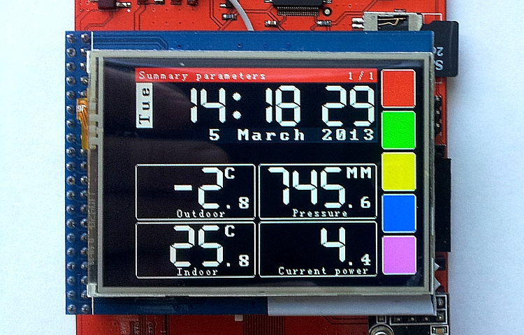
And this is another board for rapid prototyping - iBoardPro (built already on mega2560, LAN, RTC, SD, RF-interface, 40-pin connector for connecting TFT displays with touchscreen and other "buns"):
The photo clearly shows the TFT 2.4 "320 * 240 display with a resistive touchscreen ITDB02-2.4E . It looks good, but it's too small for work with your fingers, and I would like more texts (I will look towards 5 or even 7-inch displays).
Using the principles described above, this board implements (but still appends) a “control module” to which data from the desired sensors is output and it is possible to control those devices that support it.
A short video showing the current work of the prototype:
The logic of work is as follows:
- There are “main” screens - “summary” data fall on them (“Weather” - green, “House” - yellow)
- There are “sub-screens” - data from the sensors is displayed on them (in the video this is shown for the “yellow” bookmark - “home parameters”: temperature and humidity in two points of the house and data on power consumption).
- A “red” screen is a “bulletin summary” - the most requested data.
- "Blue" screen - control. In the middle of it is the control of the light, in the bottom - the control of the "forced" thermostat. At the bottom left, a red “indicator” is a display of that parameter (about which I wrote above), indicating whether the gas boiler can be operated at the current time.
The “control buttons” on the screen have “feedback”: i.e. after the inclusion of a specific mode - it is displayed in the appropriate color. If something has already been included earlier, then when you go to the control screen, it will be immediately visible.
Each "press" on the button generates a call to the sendMasterMessage function with the appropriate parameters and receiving a response from a specific sensor (it is from this data that the buttons are repainted or the value changes, as is evident for the set temperature of the "forced" thermostat).
It can be seen that there is a certain delay in “repainting” the button and changing the parameter - this is due not only to the slowness of the MC when rendering, but also because it takes time to send a request and receive a response (sometimes the “request-response” process goes more than once - master able to repeat his "order", if not wait for the expected response).
The “purple” screen is planned to be used to display data about the state of the system: current IP address, start time, last synchronization time via NTP, last “connection” times (or “auditions”) with specific sensors, etc.
Perhaps that today is all that I wanted to tell (and so it happened a long time).
Sorry for the quality of the photo - I shot the phone on the
PS “Zhelezki” acquired in this store (of course, I overpaid, but did not want to wait for a long, long time from China, during which time I managed to order and receive several parcels from the NSC). Closer and faster nowhere found.
PPS Yes, all these “glands” (well, except perhaps for a display) can be assembled at home, but that was not the goal.
Source: https://habr.com/ru/post/171613/
All Articles