Networks for the smallest. Part Seven. VPN
All issues
8. Networks for the smallest. Part Eight BGP and IP SLA
7. Networks for the smallest. Part Seven. VPN
6. Networks for the smallest. Part six. Dynamic routing
5. Networks for the smallest: Part Five. NAT and ACL
4. Networks for the smallest: Part Four. STP
3. Networks for the smallest: Part Three. Static routing
2. Networks for the smallest. Part two. Switching
1. Networks for the smallest. Part one. Connection to the equipment cisco
0. Networks for the smallest. Part zero. Planning
Buying plants in Siberia was a strategic decision for Lift mi Am. After the elevators began to drive not only up but also down, the company’s business went ... no, it flew up. Elevators began to disassemble, like hot cakes from the table. The name no longer corresponded to reality and the decision on rebranding was made. ( In fact, they were tortured by a lawsuit with Mobi ).
So, it is planned to take factories in Novosibirsk, Tomsk and Brno under LinkMiAp's wing. It's time to think about how this farm is connected to the existing network.
So, today we are considering
1) Possible connection options, their pros and cons
2) Site-to-Site VPN based on GRE and IPSec
3) Big topic: Dynamic Multipoint Virtual Network (DMVPN) in theory and practice.
')
In traditional video, only a succinct squeeze out of an article dedicated to the work and configuration of DMVPN.
When you want to link several offices, you have a huge selection of ways and means. It all depends on your capabilities, abilities, desires and the availability of equipment.
Let's take it in order.
A ) personally build a physical channel. Then it can be:
- Ethernet - twisted pair. Up to 100 meters. Maximum over the building or between adjacent buildings. Speed up to 1 Gbit / s (Strictly speaking, there is a standard 10GBASE-T, which allows data to be transmitted at a speed of 10 Gbit / s at the same distance).
- Wifi The distance depends on the implementation: it is possible to achieve a 40 km operation with powerful directional antennas. On average, up to 5 km with direct visibility. The speed depends on the standard used and the distance. It is necessary to register in “Roskomnadzor”, and, at high radiation powers, obtain permission for switching on.
- xDSL - two to four wires. The speed depends on the distance (theoretical maximum 250 Mbit / s, distance up to 6 km). Although there are rumors about the development of a standard 1Gb / c on two wires.
Or solutions like E1.There is no connection to the Internet through xDSL, namely the link: modem modem. Yes, and such solutions exist . You can call it a bridge.
- Radio Relay Lines. Distance up to several tens of kilometers. Speed up to 600 Mb / s. But this solution is already of an operator level, since it requires a lot of approvals and arrangements for planning, construction, commissioning.
- Optical fiber. 1 Gb / s (solutions for 10 and 100 Gb / s may cost unreasonably expensive). The distance depends on many factors: from several kilometers to hundreds. Coordination of cable laying, qualified personnel for construction and maintenance are required. For small companies, it only makes sense to connect the building not very far from the central hub. In general, of course, each case is individual and requires calculation.
In this case, everything is transparent for you - you use your own physical line, so you can pass anything through it without restrictions.
B) The second option is to rent the channel from the provider. In the case of the need for a stable channel to another city - this is the most common and reliable option. The provider can provide you with the following services:
- The most genuine straight cable. For example, he may loan you one or two dark fibers from his optical beam. You are free to send him everything your heart desires. On the part of the provider, this is in no way controlled, not limited, it provides only support. For example, in the event of an accident, you will not have to look for a contractor and a welding machine, but as a provider. And for the simple it is responsible. If this is not your mutual agreement (read, netting), then perhaps the most expensive way.
- L2VPN. You can also allow anything to the channel, but in this case, your traffic will go through the active equipment of the provider, so it can be limited, for example, by speed.
This term means several second-level services:
VLAN - in one form or another, a branch VLAN is provided to you.
A pseudo cable ( PWE3 ) is a Point-to-Point service when you have a cable between two nodes. All frames transmitted by you are delivered without changes to the remote point. Similarly, the opposite way. This is possible due to the fact that your frame coming to the provider's router is encapsulated in a higher-level PDU , as a rule, this is an MPLS packet.
VPLS ( Virtual Private Network ) is a simulation of a local network. In this case, the entire network provider for you will be like a kind of abstract giant switch. Like the present, it will store the table of MAC addresses and decide on where to send the incoming frame. This is also implemented by encapsulating the frame into an MPLS packet. - L3VPN. In this case, the provider's network is like a big router with several interfaces. That is, the joint at you will occur at the network level. You configure the IP addresses on your routers on both sides, but routing in the provider's network is already the headache of the provider. The IP addresses for the junction points can either be determined by you or provide by the provider - it depends on the implementation and on your agreement. It can function on the basis of GRE, IPSec or the same MPLS.
This service looks very simple from the point of view of the client - both in terms of customization and in terms of implementation - but difficult - from the point of view of the operator.
We will deal with the implementation of L2 / L3 VPN based on MPLS, but much later.
B) Well, the last option: a tunnel through a public network. Suppose you have Internet access at both your points. Often the cheapest way is to build a tunnel between these two points. To do this, you just need to have white (public) static addresses on all points (and sometimes enough on one) and the equipment on which to implement it. This solution has a number of shortcomings, which we will consider below, but nevertheless, we will stop on it today.
So, your will to choose which option to use, based on the budget, feasibility, and your ability to persuade leadership.
As part of this release, we need to connect 3 offices: in Novosibirsk, Tomsk and Brno. We agree that everywhere we will only use the Internet connection.
Connection scheme of hub and spoke nodes - in Russian, the star:

I remind you that the general scheme of the LinkMiAp network now looks like this:

But we abstract from it, pushing only on essential things.
Since we decided to implement option B, we will have to sort out the options in detail.
Today, there are an innumerable set of all kinds of applications and protocols for organizing a VPN, but most of them are ways to connect hosts, not networks. We mean remote work. For example:


That is, this is the work scheme when one employee connects to the corporate network remotely (teleworker in Cisco terminology).
Frankly, we are not very interesting, much more interesting question, how to connect entire networks.

Today we consider the most common options:
- GRE
- IPSec (tunnel and transport modes)
- GRE over IPSec
- VTI
- DMVN
GRE
Generic Routing Encapsulation is a very simple tunneling protocol.
Taxi tunneling . What is this beast? Roughly speaking, this means that your original data is taken along with service headers (usually IP, but maybe Ethernet and ATM), packed in a packet and transmitted over a public network, as if the car is traveling through a tunnel through the mountains. On the end node, the headers of the new package are removed, and your data in its original form continues its journey.
Not very clear, yes? Let us consider an example with GRE.
For now, take the abstract topology:

Two routers are connected to the Internet through static white addresses. On each of them private networks from a range of 10.0.0.0/8 are set up.
Of course, these networks are not routed on the Internet. (The picture shows a computer and a laptop, but in practice we will configure the virtual interface Loopback0)
Our task is to run a tunnel:

Thus, for PC1, when communicating with PC2, there is no Internet - both of them will think that they are on the same local network.
The GRE tunnel is configured as follows:
interface Tunnel0
ip address 10.2.2.1 255.255.255.252
Since the tunnel is a virtual L3 interface, through which we will have routing, it must be assigned an IP address, which is selected according to your IP plan, probably from a private network.
You can select the source address as the IP address of the output interface.
(white address provided by the provider) and its name (FE0 / 0 in our case):
tunnel source 100.0.0.1
The destination address is the public address of the remote side:
tunnel destination 200.0.0.1
Finished view:
interface Tunnel0
ip address 10.2.2.1 255.255.255.252
tunnel source 100.0.0.1
tunnel destination 200.0.0.1
Immediately after this, the tunnel should rise:
R1 # sh int tun 0
Tunnel0 is up, line protocol is up
Hardware is tunnel
Internet address is 10.2.2.1/30
MTU 1514 bytes , BW 9 Kbit, DLY 500000 usec,
reliability 255/255, txload 1/255, rxload 1/255
Encapsulation TUNNEL, loopback not set
Keepalive not set
Tunnel source 100.0.0.1, destination 200.0.0.1
Tunnel protocol / transport GRE / IP
All basic information is reflected here. Pay attention to the size of the MTU - it is not 1500, as it is for ordinary physical interfaces. We'll talk about the MTU parameter at the end of the article.
By default, GRE does not check the availability of the destination address and immediately sends a tunnel to Up. But one has only to add a keepalive X command to the tunnel interface, as the router starts sending Kipalaiva and does not rise until there is an answer.
In our test scheme as a local network, we simply set up Loopback interfaces - they are always in Up. Gave them addresses with a mask / 32. Actually, they mean the real subnets of your enterprise (well, like in the picture).
interface Loopback0
ip address 10.0.0.0 255.255.255.255
On the router, you should have two static routes:
ip route 0.0.0.0 0.0.0.0 100.0.0.2
ip route 10.1.1.0 255.255.255.255 10.2.2.2
The first one says that the default gateway is the provider address 100.0.0.2:
R1 # traceroute 200.0.0.1
Type escape sequence to abort.
Tracing the route to 200.0.0.1
1,100.0.0.2 56 msec 48 msec 36 msec
2,200.0.0.1 64 msec * 60 msec
The second one forwards packets addressed to the host with the address 10.1.1.0, to the next-hop 10.2.2.2 - this is the tunnel address on the reverse side.
GRE tunnels are unidirectional, and the reverse tunnel is usually implied on the other side, although generally speaking, this is not necessary. But in our case, when the Internet is in the middle, and the task is to organize a private network, on the reverse side there should be a symmetrical setting:
nsk-obsea-gw1:
interface Tunnel0
ip address 10.2.2.2 255.255.255.252
tunnel source 200.0.0.1
tunnel destination 100.0.0.1
ip route 0.0.0.0 0.0.0.0 200.0.0.2
ip route 10.0.0.0 255.255.255.255 10.2.2.1
We try to run ping:
R1 # ping 10.1.1.0 source 10.0.0.0
Type escape sequence to abort.
Sending 5, 100-byte ICMP Echos to 10.1.1.0, timeout is 2 seconds:
!!!
Success rate is 100 percent (5/5), round-trip min / avg / max = 44/71/136 ms
R1 # tracer 10.1.1.0
Type escape sequence to abort.
Tracing the route to 10.1.1.0
1 10.2.2.2 68 msec * 80 msec
Sumptuously! But what happens behind the scenes?
And there, guys, amazing things:
When you start ping 10.1.1.0, what does the router do?
1) Generates an IP packet ::

2) Looks at the routing table
R1 # sh ip route 10.1.1.0
Routing entry for 10.1.1.0/32
Known via "static", distance 1, metric 0
Routing Descriptor Blocks:
* 10.2.2.2
Route metric is 0, traffic share count is 1
Further recursively looks, where the address 10.2.2.2:
R1 # sh ip rou 10.2.2.2
Routing entry for 10.2.2.0/30
Known via "connected", distance 0, metric 0 (connected, via interface)
Routing Descriptor Blocks:
* directly connected, via Tunnel0
Route metric is 0, traffic share count is 1
Thaxss, Tunnel 0:
R1 # sh int tun 0
Tunnel0 is up, line protocol is up
Hardware is tunnel
Internet address is 10.2.2.1/30
MTU 1514 bytes, BW 9 Kbit, DLY 500000 usec,
reliability 255/255, txload 1/255, rxload 1/255
Encapsulation TUNNEL, loopback not set
Keepalive not set
Tunnel source 100.0.0.1, destination 200.0.0.1
3) Realizing that this is a GRE tunnel, adds a GRE header to the packet:

And on top of the new heading IR. The address of the tunnel source will appear as the sender, and the destination will be the destination.

4) The new package is sent to the brave world via the default route:
R1 # sh ip route
Gateway of last resort is 100.0.0.2 to network 0.0.0.0
5) Do not forget about the Ethernet header, when sending it to the provider, it must also be formed.
Since the GRE tunnel is a Layer 3 virtual interface, it does not have its own MAC address (like Loopback, for example). Finally, the frame will leave the FastEthernet0 / 0 physical interface:
R1 # sh ip route 100.0.0.2
Routing entry for 100.0.0.0/30
Known via "connected", distance 0, metric 0 (connected, via interface)
Routing Descriptor Blocks:
* directly connected, via FastEthernet0 / 0
Route metric is 0, traffic share count is 1
Accordingly, he will indicate his address as a Source MAC.
R1 # sh int
FastEthernet0 / 0 is up, line protocol is up
Hardware is Gt96k FE, address is c000.25a0.0000 (bia c000.25a0.0000)
Internet address is 100.0.0.1/30
Destination is traditionally taken from the ARP cache or obtained using an ARP request from the address 100.0.0.2:
R1 # show arp
Protocol Address Age (min) Hardware Addr Type Interface
Internet 100.0.0.1 - c000.25a0.0000 ARPA FastEthernet0 / 0
Internet 100.0.0.2 71 c001.25a0.0000 ARPA FastEthernet0 / 0

6) And in this form, the new IP packet is transmitted to the Internet. And since each router does not strip a packet, but makes a decision based on the first IP header, no one on the Internet will know that your private addresses 10.1.1.0 and 10.0.0.0 are hidden somewhere inside.

7) And finally stays at the destination.
R3 discovers that the destination address belongs to him, removes the IP header and what does he find under it? GRE header.
It checks that it does have such a GRE tunnel, removes the GRE header, and then it is the most common IP packet that you need to dispose of according to the entries in the routing table.
In this case, transfer Loopback 0 to the interface.
R3 # sh ip route 10.1.1.0
Routing entry for 10.1.1.0/32
Known via "connected", distance 0, metric 0 (connected, via interface)
Routing Descriptor Blocks:
* directly connected, via Loopback0
Route metric is 0, traffic share count is 1
Here are some simple manipulations.
While the packet is on the local network, it looks like this:

and processed on the basis of private addresses.
As soon as it enters the public network, GRE places an additional IP header on it:

and the packet is processed based on public addresses.
Here’s what the package looks like on the Internet:

1 - initial data
2 - first IP header (internal)
3 - GRE header (indicating that IP data is inside)
4 - new IP header (external, with tunnel addresses)
Ordinary ICMP messaging may look like this on a closer look .
Complete router configuration for GRE .
If you try to draw analogies with a tangible world, then imagine a situation when you are driving from the village, encapsulated in a car. You reach the river, and you need to move to the other side and continue your journey there to the city.
At the river port, your car is encapsulated in a ferry and transported through the surging waves to the other side, where your car is removed and you continue to move. So this ferry was a GRE-ferry.
We make three remarks:
First, we chose Loopback interfaces and masked addresses / 32 simply for the test, in fact, it could well be interfaces fa1 / 0.15 and fa0 / 1.16 with subnets 172.16.15.0/24 and 172.16.16.0/24, for example, or any others.
Secondly, we are all talking about public networks and addresses, but in fact, of course, it doesn’t matter and the tunnels can be lifted even inside our corporate network, when the final networks already have IP connectivity without a tunnel.
Thirdly, despite the fact that theoretically the traffic can return back and not through the tunnel, it is necessary to create it so that the end node can successfully decapsulate GRE packets
The usual GRE is a vivid example of tunneling that is very easy to configure and relatively easy to troubleshoot.
Obviously, you already guess what three big problems lurk in this field?
- Security. The data encapsulated in GRE is transmitted nonetheless in the clear.
- The difficulty of scaling. If you have 5-7 branches, the maintenance of such a number of tunnels still seems possible, and if there are 50 of them? Moreover, traffic tunneling is often performed on the CPU, especially on the younger and middle lines, so this is an extra load on the processor.
- All branches will interact with each other through the central site, although they could directly.
Ipsec
The first problem voiced above is designed to solve encryption.
Now for the organization of an encrypted VPN-channel, the following technologies are mainly used: IPSec (IP Security), OpenVPN and PPTP (Point-to-Point Tunneling Protocol).
The undisputed leader, of course, is IPSec, and we'll talk about it.
First you need to understand that IPSec is not a protocol, it is a standard that includes as many as three protocols, each with its own functions:
- ESP (Encapsulating Security Payload - secure payload encapsulation) deals directly with data encryption, and can also provide source authentication and data integrity checks.
- AH (Authentication Header) is responsible for authenticating the source and checking the integrity of the data.
- The IKE (Internet Key Exchange protocol) is used to form the IPSec SA (Security Association, more on this below), in other words, to negotiate the work of participants in a secure connection. Using this protocol, the participants agree on what encryption algorithm will be used, what algorithm will be used (and whether there will be any at all) integrity checking, how to authenticate each other
Before moving on, let's deal with the term SA - Security Association. SA is generally a set of secure connection parameters (for example, an encryption algorithm, an encryption key) that can be used by both sides of the connection. Each compound has an associated SA.
Now, in order, how to create a secure connection in IPSec:
- To begin with, the participants need to agree on what algorithms / protection mechanisms they will use for their secure connection, so IKE comes into play. The process consists of two phases:
- Phase one: the participants authenticate each other and agree on the settings for setting up a special connection (also secure) intended only for exchanging information about the desired / supported encryption algorithms and other details of the future IPSec tunnel. The parameters of this mini-tunnel (correctly called the ISAKMP Tunnel) are determined by the ISAKMP policy, the editing mode of which we can get from the configuration mode using the crypto isakmp policy policy_number . If the parties agree, an ISAKMP tunnel is established (its presence can be viewed with the show crypto isakmp sa command ), through which the second phase of IKE already passes.
- Phase two: those already trusting each other agree on how to build the main tunnel for the data. They take turns offering each other the options specified in the crypto ipsec transform-set command , and, if they come to an agreement, raise the main tunnel. It must be said that, after its establishment, the auxiliary ISAKMP tunnel does not disappear anywhere - it is used to update the main SA. The fact is that the keys chosen for encrypting information in the IPSec tunnel have a certain “lifetime” (can be expressed both in the number of bytes and in seconds - that the former will reach the threshold value), after which they must be replaced. This is like a password that you change once per hour (the default lifetime IPSec SA is 4,608,000 kilobytes / 3,600 seconds).
- Participants received an encrypted tunnel with parameters that suit them all, and send there data streams to be encrypted, that is, falling under the access list specified in the crypto map.
- Periodically, in accordance with the configured lifetime, the encryption keys for the main tunnel are updated: the participants again communicate via the ISAKMP tunnel, go through the second phase and establish new SAs.
Strictly speaking, there is a zero step in this process: some traffic must match the access list in the crypto map. Only after that all the rest will occur.
Now a little about the transform set and how ESP differs from AH. How our data going through the tunnel will be encrypted is determined by the crypto ipsec transform-set set_name command , followed by the name of the protocol to be used (ESP or AH) + algorithm that the protocol will use. For example, the crypto ipsec transform-set SET1 esp-aes command will make it clear to the router that the transform set with the name “SET1”, if applied, will work only via ESP protocol with AES encryption. Well, if everything is more or less clear with ESP, its business is to encrypt (to ensure confidentiality ), what is AH and why is it needed at all? AH provides data authentication , that is, it makes sure that this data came precisely from who we contacted and were not changed along the way. If you do not go into details, it works like this: an AH header is inserted into each packet between the IP header and the transport layer header, in which it is present:
- Information on which the recipient can understand to which SA the given package belongs (i.e., including, according to what algorithm, to consider as a hash for comparison - MD5 or SHA)
- the so-called ICV (Integrity Check Value), which is a hash of a package (in fact, not the entire package, but fields that cannot be changed during the journey), which allows the recipient to be sure that this package has not changed along the way by calculating the hash from same information and comparing the result with the value of this field.
IPSec can work in two modes: tunnel and transport.
IPSec Tunnel Mode
In this mode, your initial IP packet is taken, encrypted completely, along with the IP header, the IPSec service information and the new IP header are added:
 * the picture is not accurate and only shows the essence, in fact there are more headers, and there are also trailers at the end .
This is the default mode.
Let's see again in the course of setting.
On the local side:
First, the general policy for phase 1 is to establish the first, auxiliary tunnel: encryption type (DES default) and authentication. Authentication can be done based on certificates, but we will look at a simple example with a preshared key:
crypto isakmp policy 1
encr aes
authentication pre-share
Often, there are several such policies with different combinations of encryption, hash and DH group.
When creating isakmp sa, the party that initiates the connection sends all locally configured isakmp policies.
The host looks in turn, in order of priority, of their locally configured policies. The first policy for which a match is found will be used.
Specify the pre-shared key for neighbor authentication 200.0.0.1
crypto isakmp key CISCO address 200.0.0.1
Next, we specify the parameters for processing traffic. AES encryption algorithm using ESP header and authentication algorithm.
crypto ipsec transform-set AES128-SHA esp-aes esp-sha-hmac
In fact, we immediately specify a set of protocols, as you see, it is called transform-set. When setting up an IPSec session, routers exchange these sets. They must match.
To simplify troubleshooting, the names for the transform-set are usually given using the protocols used.
Now we create an encryption card:
crypto map MAP1 10 ipsec-isakmp
set peer 200.0.0.1
set transform-set AES128-SHA
match address 101
It is here that the IPSec neighbor address is determined, with which the tunnel will be established later - 200.0.0.1. There is also a set of protocols and an ACL, which determines which traffic will be encrypted and transmitted through the tunnel.
In our case, it looks like this:
access-list 101 permit ip host 10.0.0.0 host 10.1.1.0
Be careful when setting the ACL. It defines the parameters of not only outgoing traffic, but also incoming (as opposed to ACL for NAT, for example).
That is, if packets come not from 10.1.1.0, but from 10.2.2.2, it will not be processed and decrypted.
I mean, if we generate traffic from a host with an address of 10.0.0.0 at 10.1.1.0, then it and only it will be encrypted and sent to the IPSec tunnel. Anyone else will go the easy way.
Note that encryption occurs at the very least, after routing.
And this, by the way, is a very important moment. You do not have enough route to the public address of the peer (200.0.0.1). We need a route to 10.1.1.0 even if it is default. Otherwise, the packet will be dropped in accordance with normal routing rules.
No matter how strange it may seem, but the traffic to the local network should be “routed”, for example, to the Internet. At the same time, private packets that are about to be sent to the provider and dropped there are encrypted at the last moment, receiving public addresses.
By the way, there is a table with the order of the operations performed on the traffic.

The last step is to bind the encryption card to the interface. Until you do this the mechanism will not work.
interface FastEthernet0 / 0
crypto map MAP1
On the reverse side you need to make a symmetrical setting.
Therefore, we simply use the following configuration on R3:
crypto isakmp policy 1
encr aes
authentication pre-share
crypto isakmp key CISCO address 100.0.0.1
!
!
crypto ipsec transform-set AES128-SHA esp-aes esp-sha-hmac
!
crypto map MAP1 10 ipsec-isakmp
set peer 100.0.0.1
set transform-set AES128-SHA
match address 101
interface FastEthernet0 / 1
crypto map MAP1
access-list 101 permit ip host 10.1.1.0 host 10.0.0.0
That's all.
But no matter how much you watch a show crypto session or a show crypto isakmp sa , you will only see Down . The tunnel does not rise. Show crypto ipsec sa
counters . Also by zeros.
R1 # sh crypto session
Crypto session current status
Interface: FastEthernet0 / 0
Session status: DOWN
Peer: 200.0.0.1 port 500
IPSEC FLOW: permit ip host 10.0.0.0 host 10.1.1.0
Active SAs: 0, origin: crypto map
R1 # sh crypto isakmp sa
dst src state conn-id slot status
The fact is that you need to let traffic into it. In the literal sense, like this:
R1 # ping 10.1.1.0 source 10.0.0.0
Type escape sequence to abort.
Sending 5, 100-byte ICMP Echos to 10.1.1.0, timeout is 2 seconds:
Packet sent with a source address of 10.0.0.0
. !!!
Success rate is 80 percent (4/5), round-trip min / avg / max = 60/94/160 ms
And once you have done this, you will have success:
R1#sh crypto session
Crypto session current status
Interface: FastEthernet0/0
Session status: UP-ACTIVE
Peer: 200.0.0.1 port 500
IKE SA: local 100.0.0.1/500 remote 200.0.0.1/500 Active
IPSEC FLOW: permit ip host 10.0.0.0 host 10.1.1.0
Active SAs: 2, origin: crypto map
R1#sh crypto isakmp sa
dst src state conn-id slot status
200.0.0.1 100.0.0.1 QM_IDLE 1 0 ACTIVE
Full router configuration .
=====================
 Task number 1
Initial configuration: “IPsec”
Router R1 is located in the central office.
Router R3 is a router in one of the branches.
R4 - the second branch is added to the scheme.
Task:
1. Configure an IPsec tunnel using a crypto-map between R4 and R1:
- The data protection policies are the same as for the tunnel between R3 and R1.
2. Add the appropriate settings so that R3 and R4 can also exchange data:
- Data between the branches for R3 and R4 should be transmitted through the central R1 router.
Task details on the site
================ =====
What happened?
1) We launched the ping to the address 10.1.1.0 from the address 10.0.0.0.
2) According to the routing table, the packet must be transmitted to the public network as it is.
3) But the router sees that it falls on its ACL 101 and sends the packet to IPSec.
4) IPSec, working in tunnel mode (default mode), packs the source packet first into the IPSec PDU, simultaneously encrypting anything and everything, and then completes it with a new IP header. As a destination address, the router registers the address of its IPSec-neighbor - 200.0.0.1.
In the screenshot below you can see the encapsulation:

This was an exchange of ICMP messages. All source data is encrypted, including the old IP, the new IP header is based on the IPSec configuration.
5) At the end node, the router sees that the destination address belongs to it, removes the IP header and sees the IPSec header, to which protocol it sends the packet for processing. The latter is decrypted, all service information is deleted, and the source packet travels further.
Why did we run such a strange ping? In it, we specified the sender's address explicitly.
If we try to start Ping 10.1.1.0, it will not work, because the router automatically substitutes the physical interface address as the sender: 100.0.0.1, which does not fall into our ACL, and therefore the packet tries to go to the gateway of last resort.
What is the most important problem we have here? Bingo!Dynamic routing Implementing it in such conditions is impossible - all IGPs require a direct L2 link between neighbors, which IPSec does not provide. Therefore, in such an implementation, the traffic is sent to the tunnel based on the ACL and the encryption card, rather than the routing table.
Plus we have a problem with multicast, because we set specific subnets in the ACL.
Full router configuration .
=====================
Task number 2Configuration: "IPsec"
Note:
The problem can be solved, both theoretically and practically.
If you try the task in practice, carefully follow the conditions of the task.
Conditions of the problem:
Router R1 is located in the central office and 3 branches will be connected to it (for this task, there are enough R1, R2, R3 routers. R3 is one of the branches). Branch offices use routers with different capabilities, and you must use different IPsec policies. There are 3 different policies in total.
On router R3, in addition to the tunnel to the central office, there are also several tunnels with partners. Therefore, various politicians have also been created here.
The traffic is transmitted only from the branches to the central office, there are no communications between the branches.
From the side of the R3 branch to the central office of R1, data is generated that initiates the VPN tunnel.
Question: What data protection policy will routers use to build a tunnel between them?
Details of the tasks on the site
=====================
It was a tunnel mode, colleagues. Go to the next exhibit.
IPSec Transport Mode
It is much different from the tunnel, but the most important is the encapsulation method.
Here is an IPSec packet in tunnel mode.
And this is an IPSec packet in the transport one:

That is, the tunnel encrypts the original packet completely and adds a new IP header. The transport encrypts everything that is above the IP level, and the IP header remains unchanged.
Roughly speaking, you use tunnel mode to connect two private networks through a public one, while ensuring encryption (Something like safe GRE). Transport is relevant when IP connectivity has already been achieved, but traffic between nodes must be encrypted.
A good example of the use of transport mode can be a server-client scheme. For example, the work of client-bank. The server is already available, but the traffic needs to be encrypted.
But we are not talking about that. We still need to unite the network.
=====================
Task number 3Scheme: "final scheme of task 7.1"
Device configurations: on the project website
Description of the problem:
No data is transferred between R1 and R4.
Task:
Find the error and correct the configuration so that the tunnel between R1 and R4 is established and traffic is transmitted between R1 and R4.
Details of the tasks on the site
=====================
GRE over IPSec
Beginners often get confused here ( he happened to the author ): GRE over IPSec or IPSec over GRE. What is the difference where applied. You can not stop it.
Normal mode, which we consider here and which is used in the overwhelming majority of cases, is GRE over IPSec, that is, GRE data is encapsulated with ESP or AH headers,

and IPSec over GRE means, on the contrary, that inside will be encrypted IPSec data, and on top of GRE / headers IP. They will not be encrypted:

This option is possible, for example, if you have encryption on a separate device before tunneling.

Why such a pahabschina is needed is not very clear, therefore GRE over IPSec is usually used.
Let us return to our old scheme and implement this variant on it.
Of course, at the same time, we again have a tunnel interface (configured as usual GRE):
interface Tunnel0
ip address 10.2.2.1 255.255.255.252
tunnel source 100.0.0.1
tunnel destination 200.0.0.1
And then you send to it the traffic you need a static route.
ip route 10.1.1.0 255.255.255.255 10.2.2.2
What changes in the IPSec configuration?
In principle, even if you do not change anything, everything will already work, but this is not our way.
Firstly, since the tunnel already exists (GRE), there is no need to do it with IPSec tools - you can transfer it to transport mode, thereby saving 20 bytes on the excess IP header:
crypto ipsec transform-set AES128-SHA esp-aes esp-sha-hmac
mode transport
* Note, change, it is necessary on both sides, otherwise the IPSec neighborhood will not be established.
Secondly, all traffic between branches should be encrypted, that is, the one that goes through the tunnel, respectively, there is no need to register all networks in the ACL, we’ll get smarter:
access-list 101 permit gre host 100.0.0.1 host 200.0.0.1
The condition is met if traffic arrived on the port with the GRE header and the corresponding addresses.
What will happen in this situation?
1) The packet with the destination address 10.1.1.0 comes to the router, it determines from its table that the packet needs to be sent to next-hop 10.2.2.2
R1 # sh ip route 10.1.1.0
Routing entry for 10.1.1.0/32
Known via "static", distance 1, metric 0
Routing Descriptor Blocks:
* 10.2.2.2
Route metric is 0, traffic share count is 1
2) This is a tunnel interface, with a destination address of 200.0.0.1. The packet is packed with a GRE header and a new IP header.
R1 # sh int tun 0
Tunnel0 is up closeup, line protocol is up closeup
the Hardware is Tunnel
of Internet address is 10.2.2.1/30
the MTU 1514 bytes, BW 9 Kbit, DLY 500,000 usec,
reliability What 255/255, txload 1/255, rxload 1 / 255
Encapsulation TUNNEL, loopback not set
Keepalive not set
Tunnel source 100.0.0.1, destination 200.0.0.1
Tunnel protocol / transport GRE / IP
3) Network 200.0.0.1 is known through the address 100.0.0.2
R1 # sh ip route
Gateway of last resort is 100.0.0.2 to network 0.0.0.0
And the subnet 100.0.0.0/30 is connected to the FE0 / 0 interface
R1 # sh ip route 100.0.0.0
Routing entry for 100.0.0.0/30, 1 known subnets
Attached (1 connections)
C 100.0.0.0 is directly connected, FastEthernet0 / 0
And on it is applied encryption card with ACL.
The traffic, naturally, falls under it (it has the GRE header and the necessary IP addresses), so everything that is inside the external IP header will be encrypted.
Such a scheme of work allows the normal implementation of dynamic routing protocols, as well as multicast traffic, leaving the possibility of encryption. Hooligans will not be able to steal secret recipes for the preparation of elevators.
=====================
Problem number 5Scheme: "GRE_over_IPSec"
Configuration: on the project website
Description of the problem:
After setting up GRE over IPSec between R1 and R3, everything works fine, the traffic between R1 and R3 (from 10.0.0.0 to 10.1.1.0) is transmitted.
However, a few days later, when the administrator wanted to see the VPN status, it turned out that there are no SAs installed on the routers at all.
Accordingly, the traffic between R1 and R3 is not encrypted.
The task:
You need to check the settings, correct the configuration and make sure that the traffic is encrypted (traffic between loopback interfaces 10.0.0.0 and 10.1.1.0).
Details of the task on the site
=====================
Complete router configuration for IPSec .
You can make one more addition here: technically, you can exclude the four-byte GRE header from the packet, indicating on both sides that the IPIP tunnel is in operation mode:interface Tunnel0
tunnel mode ipip
Truth must be remembered that in this case you can only encapsulate IP data, and not any, as in the case of GRE.
=====================
Task number 4Scheme: "GRE_over_IPSec"
Configuration: "GRE_over_IPSec"
The task:
Change the initial configuration of GRE over IPSec and configure GRE over IPsec without using a crypto-map.
Details of the task on the site
=====================
IPSec VTI
The latest example of a Site-to-Site VPN using IPSec, which, in fact, is recommended by ciskoy - VTI (Virtual Tunnel Interface)
IPSec configuration is different in that we no longer need to manually create a crypto-map (and, accordingly, an ACL), instead we create an IPSec profile
crypto isakmp policy 1
authentication pre-share
crypto isakmp key DMVPNpass address 0.0.0.0 0.0.0.0
crypto ipsec transform-setVTI-TS esp-aes
mode transport
crypto ipsec profile VTI-P
set transform-set VTI-TS
And in turn, it must be tied to the tunnel interface.
interface Tunnel0
tunnel protection ipsec profile DMVPN-P
The difference from the previously used Crypto map is that now there is no need to create an ACL - all traffic that enters the tunnel is encrypted (encryption cards are still generated, but automatically).
It turned out the usual Tunnel Protection without VTI. It is also widely used.
The tunnel mode ipsec ipv4 command indicates VTI usage.
The difference from the usual GRE in encapsulation methods - VTI saves 4 bytes by excluding the GRE header.
Small description
Complete router configuration for IPSec VTI .
DMVPN
The apotheosis of today's release is DMVPN (Dymamic Multipoint VPN). So far, we have been talking about universal venderozavisimyh things. Unfortunately, DMVPN is a purely ciskovian thing and has not yet opened adequate analogs (correct it if I am mistaken).
In the previous parts, we solved the problem with the security of the transmitted data - now we encrypt them - and with IGP - through GRE over IPSec we use dynamic routing protocols.
The last problem remains - scalability.
Well, when you have this mesh:

Two tunnels on each node and that's it.
Add another node:

And one more:

Much more tunnels are needed to obtain a fully connected topology. A typical problem with m * (m-1) / 2 complexity.
If you do not use Full-Mesh, but turn to the Hub-and-Spoke topology with one central point, then another problem arises - traffic between any branches will pass through the central node.
DMVPN solves both problems.
The point is this: the central point of the Hub (or several) is selected. It will be the server to which clients will connect (Spoke) and receive all the necessary information. Wherein:
1) Data will be encrypted by IPSec
2) Customers can send traffic directly to each other, bypassing the central site
3) Only a central site requires a static public IP address. Remote nodes can have a dynamic address and even be behind a NAT, using addresses from private ranges ( NAT Traversal ). But at the same time there are restrictions on the part of dynamic tunnels.
This is all the focus of the power of GRE and IPSec, flavored with NHRP and IGP.
Theory and Practice of DMVPN
Abstracting from our old network, we take into consideration only Moscow, the Internet, which will be emulated by the Balagan-Telecom router, and the actual branches in Novosibirsk, Tomsk and Brno:
New IP plan:
Subnets allocated to connect to the Internet affiliates:

LAN:

For tunnel interfaces, take the internal network:

And we will also assign Loopback addresses for them:

The idea is that the central node will have a single dynamic tunnel, which we will set up at the very beginning, and when adding new remote points, no changes are needed here - neither to add new tunnel interfaces, nor to reconfigure the existing one.
In fact, when adding new nodes, you only need to configure them.
NHRP - NBMA Next Hop resolution Protocol is running everywhere.
It allows you to dynamically study the addresses of remote points that you want to connect to the main.
It is based on the possibility of implementing multipoint VPN. The hub (central site) here acts as a server (NHS - Next-Hop Server), and all remote sites will be clients (NHC - Next-Hop Client).
It sounds difficult. To explain on the fingers, too, will not work. You only need to set up once and see how the packages run.
Hub configuration:
interface Tunnel0
ip address 172.16.254.1 255.255.255.0
ip nhrp map multicast dynamic
ip nhrp network-id 1
tunnel source FastEthernet0 / 1.6
tunnel mode gre multipoint
In order:
ip address 172.16.254.1 255.255.255.0 - IP address from the desired range.
ip nhrp map multicast dynamic - Dynamic exploring NHRP data from clients. Since we have a lot of customers and they can be with dynamic addresses, it is impossible to set an explicit correspondence of internal and external addresses on the hub.
ip nhrp network-id 1 - Determine the Network ID - just an identifier that does not have to be the same on all DMVPN nodes (similar to the OSPF Router-ID).
tunnel source FastEthernet0 / 1.6 - legacy GRE - binding to the physical interface.
tunnel mode gre multipoint - A tunnel at the central site will terminate all tunnels from remote points. That is, it will be a point-to-multipoint.
Branch Configuration:
interface Tunnel0
ip address 172.16.254.2 255.255.255.0
ip nhrp map 172.16.254.1 198.51.100.2
ip nhrp map multicast 198.51.100.2
ip nhrp network-id 1
ip nhrp nhs 172.16.254.1
ip nhrp registration no-unique
tunnel source FastEthernet0 / 0
tunnel mode gre multipoint
In order:
ip address 172.16.254.2 255.255.255.0 - IP address from the desired range.
ip nhrp map 172.16.254.1 198.51.100.2 - Static ratio of internal and external addresses of the hub.
ip nhrp map multicast 198.51.100.2 multicast traffic should receive a hub.
Without this command you will have quite interesting symptoms of the problem.
Here you run OSPF, the peering rises, the hub and branches go to Full, exchanged routes, and you are happy that everything is fine, and then bang - ping disappears, peering drops, but only on one side, the pier is dead.
* Mar 1 01: 51: 20.331:% OSPF-5-ADJCHG: Process 1, Nbr 172.16.255.2 on Tunnel0 from FULL to DOWN, Neighbor Down: Dead timer expired
msk-arbat-gw1 #
* Mar 1 01: 51: 25.435:% OSPF-5-ADJCHG: Process 1, Nbr 172.16.255.2 on Tunnel0 from LOADING to FULL, Loading Done
What kind of garbage?
Watch debug, watch dumps
* Mar 1 01: 53: 44.915: OSPF: Send hello to 224.0.0.5 area 0 on FastEthernet0 / 1.4 from 172.16.2.1
* Mar 1 01: 53: 44.919: OSPF: Send hello to 224.0.0.5 area 0 on FastEthernet0 / 1.7 from 172.16.2.33
* Mar 1 01: 53: 44.923: OSPF: Send hello to 224.0.0.5 area 0 on FastEthernet0 / 1.5 from 172.16.2.17
* Mar 1 01: 53: 44.923: OSPF: Send hello to 224.0.0.5 area 0 on FastEthernet0 / 1.8 from 172.16.2.129
* Mar 1 01: 53: 44.963: OSPF: Send hello to 224.0.0.5 area 0 on Tunnel0 from 172.16.254.1
msk-arbat-gw1 #
* Mar 1 01: 53: 54.919: OSPF: Send hello to 224.0.0.5 area 0 on FastEthernet0 / 1.4 from 172.16.2.1
* Mar 1 01: 53: 54.923: OSPF: Send hello to 224.0.0.5 area 0 on FastEthernet0 / 1.7 from 172.16.2.33
* Mar 1 01: 53: 54.927: OSPF: Send hello to 224.0.0.5 area 0 on FastEthernet0 / 1.5 from 172.16.2.17
* Mar 1 01: 53: 54.931: OSPF: Send hello to 224.0.0.5 area 0 on FastEthernet0 / 1.8 from 172.16.2.129
* Mar 1 01: 53: 54.963: OSPF: Send hello to 224.0.0.5 area 0 on Tunnel0 from 172.16.254.1
msk-arbat-gw1 #
* Mar 1 01: 54: 04.919: OSPF: Send hello to 224.0.0.5 area 0 on FastEthernet0 / 1.4 from 172.16.2.1
* Mar 1 01: 54: 04.927: OSPF: Send hello to 224.0.0.5 area 0 on FastEthernet0 / 1.7 from 172.16.2.33
* Mar 1 01: 54: 04.931: OSPF: Send hello to 224.0.0.5 area 0 on FastEthernet0 / 1.5 from 172.16.2.17
* Mar 1 01: 54: 04.935: OSPF: Send hello to 224.0.0.5 area 0 on FastEthernet0 / 1.8 from 172.16.2.129
* Mar 1 01: 54: 04.963: OSPF: Send hello to 224.0.0.5 area 0 on Tunnel0 from 172.16.254.1
On the 5 OSPF Hello from the hub, only one Hello from the branch.
As you already understood, the router simply cannot figure out where to send multicast messages to the address 224.0.0.5, the hub does not receive them, and pulls the OSPF session.
ip nhrp network-id 1 - Network ID. It does not have to be the same as the one on the hub.
ip nhrp nhs 172.16.254.1 - Statically configured address of the NHRP server - hub. That is why in the center we need a static public address. Clients send a registration request to hub 172.16.254.1. This request contains the configured local address of the tunnel interface, as well as its public address (the case when the client is behind NAT is not yet considered).
The hub records the received information in its NHRP address matching table. It spreads the same table on request to any Spoke-router.
ip nhrp registration no-unique - if the address in the branches is issued dynamically, this command is required.
tunnel source FastEthernet0 / 0 - binding to the physical interface.
tunnel mode gre multipoint - indicate that the tunnel type is mGRE - this will allow you to create dynamically tunnels not only to the hub, but also to other branches.
Our situation is simple - without NAT - and we can already check the status of the tunnels.
msk-arbat-gw1 # sh int tun 0
Tunnel0 is up, line protocol is up
Hardware is tunnel
Internet address is 172.16.254.1/24
MTU 1514 bytes, BW 9 Kbit, DLY 500000 usec,
reliability 255/255, txload 1/255, rxload 1/255
Encapsulation TUNNEL, loopback not set
Keepalive not set
Tunnel source 198.51.100.2 (FastEthernet0 / 1.6), destination UNKNOWN
Tunnel protocol / transport multi-GRE / IP
Key disabled, sequencing disabled
Checksumming of packets disabled
msk-arbat-gw1 # ping 172.16.254.2
Type escape sequence to abort.
Sending 5, 100-byte ICMP Echos to 172.16.254.2, timeout is 2 seconds:
!!!
Success rate is 100 percent (5/5), round-trip min / avg / max = 176/213/284 ms
msk-arbat-gw1 # sh ip nhrp brief
Target Via NBMA Mode Intfc Claimed
172.16.254.2/32 172.16.254.2 198.51.101.2 dynamic Tu0
msk-arbat-gw1 # sh ip nhrp
172.16.254.2/32 via 172.16.254.2, Tunnel0 created 00:09:48, expire 01:50:11
Type: dynamic, Flags: authoritative unique registered
NBMA address: 198.51.101.2
nsk-obsea-gw1 # sh ip nhrp brief
Target Via NBMA Mode Intfc Claimed
172.16.254.1/32 172.16.254.1 198.51.100.2 static Tu0
Ospf
That is, connectivity is already provided, but the branches cannot work yet - routing is not configured.
Here for each protocol their subtleties emerge.
Let's take a look at the OSPF configuration process, for example.
Since we have a broadcast L2 network on the tunnel interfaces, we explicitly indicate the type of the Broadcast network on the tunnel interfaces on all nodes:
ip ospf network broadcast
In addition, DR should be selected on such a network. It is logical that they become a hub. All Spoke-routers prohibit participation in DR elections:
ip ospf priority 0
Well and, naturally, we define the announced networks.
router ospf 1
network 172.16.0.0 0.0.255.255 area 0
Networks are announced:
msk-arbat-gw1 # sh ip route
Gateway of last resort is 198.51.100.1 to network 0.0.0.0
172.16.0.0/16 is variably subnetted, 7 subnets, 3 masks
C 172.16.2.128/30 is directly connected, FastEthernet0 / 1.8
C 172.16.255.1/32 is directly connected, Loopback0
C 172.16.254.0/24 is directly connected, Tunnel0
C 172.16.2.32/30 is directly connected, FastEthernet0 / 1.7
C 172.16.2.16/30 is directly connected, FastEthernet0 / 1.5
C 172.16.2.0/30 is directly connected, FastEthernet0 / 1.4
O 172.16.255.128/32 [110/11112] via 172.16.254.2, 00:05:14, Tunnel0
198.51.100.0/28 is subnetted, 1 subnets
C 198.51.100.0 is directly connected, FastEthernet0 / 1.6
S * 0.0.0.0/0 [1/0] via 198.51.100.1
Ping passes
msk-arbat-gw1 # ping 172.16.255.128
Type escape sequence to abort.
Sending 5, 100-byte ICMP Echos to 172.16.255.128, timeout is 2 seconds:
!!!
Success rate is 100 percent (5/5), round-trip min / avg / max = 60/70/80 ms
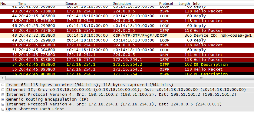
Here are the packets transmitted via the Internet:
 * Dump with nsk-obsea-gw1 fa0 / 0
We check how we ping from one branch to another:
nsk-obsea-gw1 # ping 172.16.255.132
Type escape sequence to abort.
Sending 5, 100-byte ICMP Echos to 172.16.255.132, timeout is 2 seconds:
!!!
Success rate is 100 percent (5/5), round-trip min / avg / max = 132/231/492 ms
nsk-obsea-gw1 # traceroute 172.16.255.132
Type escape sequence to abort.
Tracing the route to 172.16.255.132
1,172.16.254.3 240 msec * 172 msec
nsk-obsea-gw1 # sh ip nhrp br
Target Via NBMA Mode Intfc Claimed
172.16.254.1/32 172.16.254.1 198.51.100.2 static Tu0
172.16.254.3/32 172.16.254.3 198.51.102.2 dynamic Tu0
As you can see, the packets do not go to the hub, but go directly directly to the router of another branch via the Internet. But the reality is somewhat more complicated.
What happens at this moment?
1) We send ping to the address of the Loopback interface in Tomsk
2) According to the routing table, the next hop
nsk-obsea-gw1 # sh ip route 172.16.255.132
Routing entry for 172.16.255.132/32
Known via "ospf 1", distance 110, metric 11112, type intra area
Last update from 172.16.254.3 on Tunnel0, 00:18:47 ago
Routing Descriptor Blocks:
* 172.16.254.3, from 172.16.255.132, 00:18:47 ago, via Tunnel0
Route metric is 11112, traffic share count is 1
This is the address from the network directly connected to the interface Tunnel 0
nsk-obsea-gw1 # sh ip route 172.16.254.3
Routing entry for 172.16.254.0/24
Known via "connected", distance 0, metric 0 (connected, via interface)
Routing Descriptor Blocks:
* directly connected, via Tunnel0
Route metric is 0, traffic share count is 1
3) According to the interface settings, NHRP is used here. We look at the correspondence table received from the hub
nsk-obsea-gw1 # sh ip nhrp brief
Target Via NBMA Mode Intfc Claimed
172.16.254.1/32 172.16.254.1 198.51.100.2 static Tu0
As you can see, the address 172.16.254.3 nhrp is unknown .
Therefore, the ICMP packet is sent to the statically configured hub - 198.51.100.2:
msk-arbat-gw1, fa0 / 1:

And the hub immediately redirects the request to the desired address:
msk-arbat-gw1, fa0 / 1:

4) At the same time, the router client in Novosibirsk sends an NHRP request, saying that someone harboring the address 172.16.254.3:
msk-arbat-gw1, fa0 / 1:

5) The hub has this knowledge:
msk-arbat-gw1 # sh ip nhr br
Target Via NBMA Mode Intfc Claimed
172.16.254.2/32 172.16.254.2 198.51.101.2 dynamic Tu0
172.16.254.3/32 172.16.254.3 198.51.102.2 dynamic Tu0
And sends this information in the NHRP response:
msk-arbat-gw1, fa0 / 1:

More Hub does not intervene in the conversation of two spokes.
6) ICMP request came to Tomsk:
tmsk-lenina-gw1, fa0 / 0:

Despite the fact that in the external header, the source IP address is the hub address, the initial address of the Novosibirsk router appears inside:
7) Tomsk also does not know anything about the address 172.16.254.2, which sent the ICMP request.
tmsk-lenina-gw1 (config-if) #do sh ip nh br
Target Via NBMA Mode Intfc Claimed
172.16.254.1/32 172.16.254.1 198.51.100.2 static Tu0
Therefore, it sends the ICMP reply to the hub too:
tmsk-lenina-gw1, fa0 / 0:

8) Following him, he is interested in the public address of the sender:
tmsk-lenina-gw1, fa0 / 0:

9) Well, the hub naturally answers:
tmsk-lenina-gw1, fa0 / 0:

10) Now on all nodes relevant information NHRP:
msk-arbat-gw1 (config-if) #do sh ip nhr br
Target Via NBMA Mode Intfc Claimed
172.16.254.2/32 172.16.254.2 198.51.101.2 dynamic Tu0
172.16.254.3/32 172.16.254.3 198.51.102.2 dynamic Tu0
nsk-obsea-gw1 (config-if) #do sh ip nhr br
Target Via NBMA Mode Intfc Claimed
172.16.254.1/32 172.16.254.1 198.51.100.2 static Tu0
172.16.254.3/32 172.16.254.3 198.51.102.2 dynamic Tu0
tmsk-lenina-gw1 (config-if) #do sh ip nh br
Target Via NBMA Mode Intfc Claimed
172.16.254.1/32 172.16.254.1 198.51.100.2 static Tu0
172.16.254.2/32 172.16.254.2 198.51.101.2 dynamic Tu0
As you can see, the distribution does not occur automatically, but on request, and only the clients are the initiators, because in fact, only they know where to turn (the hub initially does not know anything about the clients)
11) It will send the next ICMP request in a new way:
nsk-obsea-gw1 # sh ip route 172.16.255.132
Routing entry for 172.16.255.132/32
Known via "ospf 1", distance 110, metric 11112, type intra area
Last update from 172.16.254.3 on Tunnel0, 00:20:24 ago
Routing Descriptor Blocks:
* 172.16.254.3, from 172.16.255.132, 00:20:24 ago, via Tunnel0
Route metric is 11112, traffic share count is 1
Subnet 172.16.254.0 connected to the interface Tunnel 0
nsk-obsea-gw1 # sh ip route 172.16.254.3
Routing entry for 172.16.254.0/24
Known via "connected", distance 0, metric 0 (connected, via interface)
Routing Descriptor Blocks:
* directly connected, via Tunnel0
Route metric is 0, traffic share count is 1
12) We repeat a little, but ... The Tunnel 0 interface is mGRE and according to the NHRP table all traffic for which the next hop is 172.16.254.3 should be encapsulated into GRE and the external IP header with the destination address 198.51.102.2 (The source address will be selected physical interface address - 198.51.101.2):
nsk-obsea-gw1 (config-if) #do sh ip nhr br
Target Via NBMA Mode Intfc Claimed
172.16.254.1/32 172.16.254.1 198.51.100.2 static Tu0
172.16.254.3/32 172.16.254.3 198.51.102.2 dynamic Tu0
tmsk-lenina-gw1, fa0 / 0:

13) And then the packet with the destination address 198.51.102.2 is sent according to the routing table:
Gateway of last resort is 198.51.101.1 to network 0.0.0.0
Here it is important to understand that despite the fact that communication between branches is bypassing the central hub, the hub, however, carries a vital auxiliary function here and will not work without it: it provides clients with an NHRP table, and also announces all routes - the branches distribute routing information is not directly to each other, but through the hub.
Current configuration of nodes:
msk-arbat-gw1
interface Tunnel0
ip address 172.16.254.1 255.255.255.0
no ip redirects
ip nhrp map multicast dynamic
ip nhrp network-id 1
ip ospf network broadcast
ip ospf 10
tunnel source FastEthernet0 / 1.6
tunnel mode gre multipoint
nsk-obsea-gw1
interface Tunnel0
ip address 172.16.254.2 255.255.255.0
no ip redirects
ip nhrp map 172.16.254.1 198.51.100.2
ip nhrp map multicast 198.51.100.2
ip nhrp network-id 1
ip nhrp nhs 172.16.254.1
ip ospf network broadcast
ip ospf priority 0
tunnel source FastEthernet0/0
tunnel mode gre multipoint
tmsk-leneina-gw1
interface Tunnel0
ip address 172.16.254.3 255.255.255.0
no ip redirects
ip nhrp map 172.16.254.1 198.51.100.2
ip nhrp map multicast 198.51.100.2
ip nhrp network-id 1
ip nhrp nhs 172.16.254.1
ip ospf network broadcast
ip ospf priority 0
tunnel source FastEthernet0/0
tunnel mode gre multipoint
end
Currently the following problems have been solved:
1) Connectivity. Branches are connected and available.
2) Routing. Through mGRE, IGP tunnels are successfully launched.
3) Scalability. When adding a new spoke-router, only it is configured itself and there is no need to go into the configuration of already existing nodes.
4) Unloaded the hub - only service traffic is transmitted through it.
It remains to settle the issue with security.
Ipsec
This is solved as before - encryption.
If for the Site-to-Site VPN we could still use the pre-shared key, because we rigidly set the IPSec peer address, in the case of DMVPN we need flexibility, and we don’t know in advance the address of our neighbors.
In this regard, the use of certificates is recommended. On xgu there is a good article on the center of certificates on cisco.
But for simplicity’s sake, we’ll take the setup with the pre-shared key.
crypto isakmp policy 1
authentication pre-share
From the Tunnel Protection and VTI discussed above, it will differ using the template address:
crypto isakmp key DMVPNpass address 0.0.0.0 0.0.0.0
The danger here is that you can set up an IPSec session with a hub, knowing the key, any device.
Here you can safely use the transport mode:
crypto ipsec transform-set AES128-SHA esp-aes esp-sha-hmac
mode transport
crypto ipsec profile DMVPN-P
set transform-set AES128-SHA
Next, the created profile is applied to the tunnel interface. The configuration on all nodes is the same.
interface Tunnel0
tunnel protection ipsec profile DMVPN-P
Now packets transmitted over the Internet will be encrypted:
msk-arbat-gw1, fa0 / 1:

Just do not think of putting tunnel mode ipsec ipv4 :)
IPSec tunnels and encryption cards will be created dynamically for data transmission between branches and will be permanent for Hub channels -Spoke.
NAT-Traversal
Here we will not go into the principles of the NAT-T. I will only convey the essence: at the expense of an additional UDP header, IPSec can build a tunnel through NAT. This allows you to build a VPN, even on those sites where you do not have a public address.
There is no need to activate this function in any special way and configure it - it works by default.
Let's complicate the scheme by adding another router to Brno.

For example, this is a provider piece of hardware that carries out the tension. That is, in fact, on the branch office router we will have a dynamic address from the private range on the physical interface. GRE in its pure form can not build a VPN under these conditions, IPSec can, but is difficult to configure. mGRE in conjunction with IPSec can easily!
Let's see what the NHRP table looks like in this case:
msk-arbat-gw1 # show ip nhrp brief
Target Via NBMA Mode Intfc Claimed
172.16.254.4/32 172.16.254.4 10.0.0.2 dynamic Tu0
That is, he still studied the private address allocated by the provider.
It should be noted that in the routing table there should be a route to this private address, issued by the provider in the branch, even if the default one.
On the tunnel interface, we have IPSec activated, so there should be encryption cards:
msk-arbat-gw1#show crypto map
Crypto Map «Tunnel0-head-0» 65537 ipsec-isakmp
Map is a PROFILE INSTANCE.
Peer = 198.51.103.2
Extended IP access list
access-list permit gre host 198.51.100.2 host 10.0.0.2
Current peer: 198.51.103.2
Security association lifetime: 4608000 kilobytes/3600 seconds
PFS (Y/N): N
Transform sets={
AES128-SHA,
}
Interfaces using crypto map Tunnel0-head-0:
Tunnel0
Thus, the encrypted tunnel is built between 198.51.100.2 and 198.51.103.2, further, the data is still encrypted with NAT-T in the tunnel go to 10.0.0.2. And then you already know.
Explanatory detailed article on NHRP .
=====================
Task number 6Initial configuration: "DMVPN"
Scenario:
The DMVPN network was fully operational, everything worked correctly.
But after rebooting the hub msk-arbat-gw1 strange behavior began.
Task:
1. Check the network operability.
2. Restart the hub
3. After the restart, check the network operability again
4. Fix the problem:
4.1. (minimum) Make the network work again
4.2.Make the network restore automatically after the hub appears again.
Details of the tasks on the site
=====================
TShoot IPSec
Lastly, I want to say a few words about how to solve problems with IPSec. The procedure is far from trivial.
When troubleshooting VPNs, debugs play a huge role. The method of a close look at a config is less reliable - it is easy to miss a small error.
An extremely valuable tool in IPSec troubleshooting is sh crypto ipsec sa . No, the point is not even in the binary “has risen - it has not risen”, but in the counters, first of all encaps-decaps . You can start a continuous ping and observe which of the counters is growing. Most of the problems can be localized in this way.
Counters do not grow at all? See where the crypto map is applied and is everything fine with the ACL.
Grow error ? Something is wrong with the agreement, see debag.
Grow encaps , but no decaps ? Forward to study the opposite side of the tunnel, everything is fine.
MTU
Finally, we discuss one insidious moment - the size of the MTU. In the life of every system / network administrator, there comes a time when the symptoms of the problem are as follows: Yandex opens, ping works, but no other site is accessible and Outlook connects.
The devil is in the amount of MTU and the availability of additional headers.
MTU - Maximum Transmission Unit. This is the maximum data block size that can be transmitted via the interface. This concept is located at the intersection of L2 and L3 and its interpretation may vary for different vendors.
For example, the typical MTU size for a physical L3 interface is 1500. That is, roughly speaking, an 1500-byte IP packet will be processed and 1501 will be dropped or fragmented. Often packet fragmentation is prohibited, and therefore large packets are discarded.
If you are using tunneling, the packet size increases with additional headers (GRE, IPSec, etc.)
For example, for GRE: 24 bytes (GRE, New IP).
For GRE over IPSec: 56 or more bytes (depending on the operation mode and type of encryption)
For PPPoE: 36 (PPP, PPPoE, Ethernet)
The tunnel interface itself has a standard MTU 1514 and passes such packets, but the provider has an MTU = on the physical interface 1500, and the packet will be dropped on it:
R1#sh int tun 0
Tunnel0 is up, line protocol is up
Hardware is Tunnel
Internet address is 10.2.2.1/30
MTU 1514 bytes , BW 9 Kbit, DLY 500000 usec,
R1#sh int fa0/1
FastEthernet0/1 is administratively down, line protocol is down
Hardware is Gt96k FE, address is c000.19ac.0001 (bia c000.19ac.0001)
MTU 1500 bytes , BW 10000 Kbit, DLY 1000 usec,
That is, you must take into account not only your own settings, but also the settings of all intermediate nodes.
Often you do not have the opportunity to influence the MTU along the way.
Therefore, you can reduce the MTU, on the local side, use the Path MTU Discovery mechanism, or even configure the MSS - Maximum Segment Size (already applies to TCP).
Read more about problems with MTU here and here.
For various tunnels, this is a completely typical problem.
Why do ping and yandex work?
The ICMP Request and Relpy packets are 32 to 64 bytes in size, ya.ru returns very little information, which fits into the allowed size of 1500 along with all the headers.
PSUnfortunately, the following interesting topics remained unaffected:
Fully flew past the topic of remote access for employees.
In addition, the FlexVPN topic is very relevant now. This is a new stage in the development of VPN technology. But it uses IKE version 2 and is supported at the moment, as usual only with cisco equipment.
We would really like to pay attention to this and that and those topics, but it’s impossible to put everything in the framework of one article.
Release materials
IP plan
Device configuration GRE , IPSec , GRE over IPSec , VTI , DMVPN )
useful links
The IPSec
www.firewall.cx/networking-topics/protocols/870-ipsec-modes.html
www.tcpipguide.com/free/t_IPSecModesTransportandTunnel.htm
the DMVPN
www.anticisco.ru/blogs/?tag=dmvpn
xgu.ru/wiki/ % D0% 9D% D0% B0% D1% 81% D1% 82% D1% 80% D0% BE% D0% B9% D0% BA% D0% B0_DMVPN_% D0% BD% D0% B0_% D0% BC% D0 % B0% D1% 80% D1% 88% D1% 80% D1% 83% D1% 82% D0% B8% D0% B7% D0% B0% D1% 82% D0% BE% D1% 80% D0% B0 % D1% 85_Cisco
NHRP.
habrahabr.ru/post/84738
blog.ine.com/tag/nhrp
FlexVPN.
www.cisco.com/en/US/docs/ios-xml/ios/sec_conn_ike2vpn/configuration/15-2mt/sec-intro-ikev2-flex.html
habrahabr.ru/post/160555
alexandremspmoraes.wordpress.com/2012/ 06/28 / hello-world-simple-lan-to-lan-flex-vpn-configuration
alexandremspmoraes.wordpress.com/2012/07/02/flex-vpn-sample-lan-to-lan-configuration-with-dynamic-routing This
article was prepared for you by eucariot and thegluck
For brain-agonizing tasks, thanks to Natasha .
Thanks for the comments and help JDima .
The cycle “Networks for the smallest” has its own website: linkmeup.ru , where you can find all the issues neatly folded and ready for thoughtful reading.
And as a moment of self-promotion: last week there was a zero release of a podcast for telecommunications operators.
Source: https://habr.com/ru/post/170895/
All Articles