Hours on gas-discharge indicators
This article will focus on the manufacture of original and unusual watches. Their unusualness lies in the fact that the time is indicated using digital indicator lamps. Such lamps, once, was released a huge amount, both here and abroad. They were used in many devices, ranging from clocks to measuring equipment. But after the advent of LED indicators, the lamps gradually fell out of use. And now, thanks to the development of microprocessor technology, it has become possible to create watches with a relatively simple scheme on digital indicator lamps.
I think it would not be superfluous to say that two types of lamps were mainly used: fluorescent and gas-discharge. The advantages of fluorescent indicators include low operating voltage and the presence of several discharges in one lamp (although there are also such instances among gas-discharge ones, but it is much more difficult to find them). But all the advantages of this type of lamp covers one huge minus - the presence of phosphor, which eventually burns out, and the glow dims or stops. For this reason, do not use used lamps.
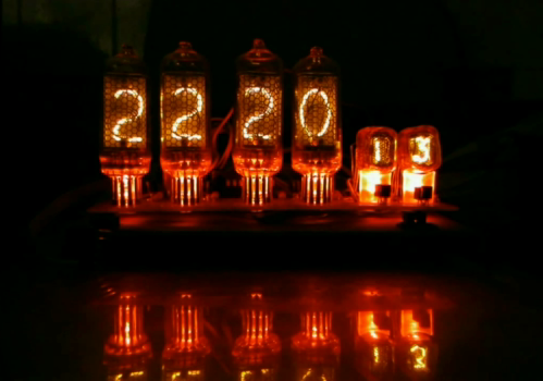
Gas-discharge indicators are free from this disadvantage, since they glow gas discharge. In fact, this type of lamp is a neon lamp with several cathodes. Due to this, the service life of gas discharge indicators is much longer. In addition, new and used lamps work equally well (and often used ones work better). However, it didn’t do without disadvantages - the working voltage of gas-discharge indicators is more than 100 V. But the issue of voltage is much easier to solve than with a burnable phosphor. On the Internet, such watches are distributed under the name NIXIE CLOCK:
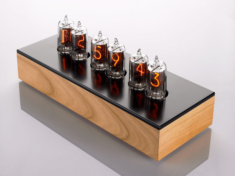
')
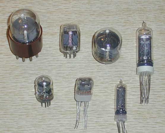
The indicators themselves look like this:
So, at the expense of design features like everything is clear, now we proceed to the design of the scheme of our watches. Let's start with the design of a high voltage source. There are two ways. The first is to apply a transformer with a secondary winding for 110-120 V. But such a transformer will either be too bulky, or it will have to be shaken up itself (the prospect is so-so). And the voltage is problematic to regulate. The second way is to assemble a step up converter. Well, there will be more advantages: firstly, it will take up little space, secondly, it has protection against short-circuits and, thirdly, you can easily adjust the output voltage. In general, there is everything that is necessary for happiness. I chose the second path because there was no desire to look for a transformer and a magnet wire, and I also wanted a miniature. It was decided to assemble the converter on the MC34063, since had experience with her. It turned out this scheme:
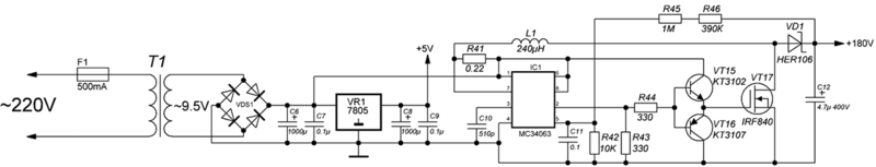
At first it was assembled on a breadboard and showed excellent results. Everything started right away and no configuration was required. When powered from 12V. the output is 175V. In assembled form, the power supply of the watch looks like this:
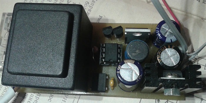
The LM7805 linear stabilizer was immediately installed on the board to power the clock electronics and a transformer.
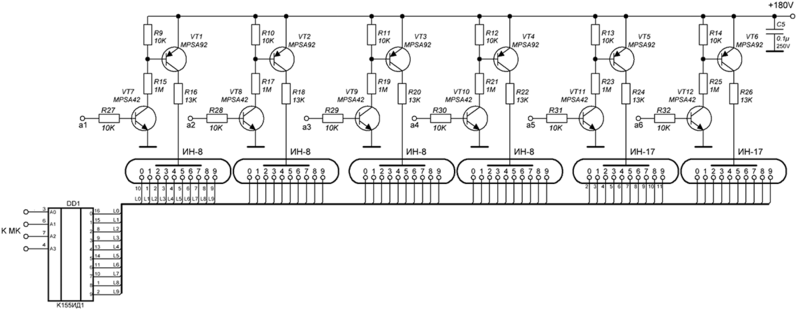
The next stage of development was the design of the lamp switching circuit. In principle, lamp control is no different from control of seven-segment indicators, with the exception of high voltage. Those. it is enough to apply a positive voltage to the anode, and connect the corresponding cathode with the power supply minus. At this stage it is required to solve two problems: coordination of the levels of the MK (5V) and lamps (170V), and switching of the cathodes of the lamps (they are numbers). After some time of reflection and experimentation, this scheme was created to control the anodes of the lamps:

And the management of the cathodes is very easy, for this purpose they invented a special chip K155ID1. True, they have long been discontinued, as are the lamps, but buying them is not a problem. Those. to control the cathodes, you only need to connect them to the corresponding pins of the microcircuit and send the input data in binary format. Yes, I almost forgot, she eats from 5B. (well, very handy thing). It was decided to make the indication dynamic, since otherwise I would have to put K155ID1 on each lamp, and there will be 6 of them. The general scheme was as follows:
Under each lamp, I installed a bright LED of the red color of the glow (so beautiful). When assembled, the board looks like this:

The panels for the lamps could not be found, so I had to improvise. As a result, old connectors, similar to modern COM, were disassembled, contacts were extracted from them, and after some manipulations with nippers and file files they were soldered to the board. I didn’t do panels for IN-17, I did it only for IN-8.
The most difficult thing is over, it remains to develop a “brain” circuit for the clock. For this, I chose the Mega8 microcontroller. Well, after that everything is quite easy, just take and connect everything to it as it is convenient for us. As a result, 3 control buttons appeared in the clock circuit, a DS1307 real-time clock chip, a DS18B20 digital thermometer, and a pair of transistors to control the backlight. For convenience, we connect the anode keys to one port, in this case it is port C. When assembled, it looks like this:


There is a small error on the board, but it is fixed in the attached board files. Wired soldered connector for firmware MK, after flashing the device should be soldered.
Well, now it would be nice to draw a general scheme. It is said - done, here it is:

And this is how it all looks completely assembled:

Now it remains only to write the firmware for the microcontroller, which was done. The functional turned out the following:
Display time, date and temperature. By briefly pressing the MENU button, the display mode changes.
1 mode - only time.
Mode 2 - time 2 min. date 10 sec.
3 mode - time 2 min. temperature 10 sec.
4 mode - time 2 min. date 10 sec. temperature 10 sec.
When held, the time and date setting is enabled, and the settings are accessed by pressing the MENU button.
The maximum number of sensors DS18B20 - 2. If the temperature is not needed, you can not put them at all, the work hours will not affect. Hot-plug sensors are not provided.
By briefly pressing the UP button, the date is switched on for 2 seconds. When held, the backlight turns on / off.
By briefly pressing the DOWN button, the temperature is turned on for 2 seconds.
From 00:00 to 7:00 the brightness is reduced.
This whole thing works like this:
The source code of the firmware is attached to the project. The code contains comments so it will not be difficult to change the functionality. The program is written in Eclipse, but the code without any changes is compiled into AVR Studio. MK operates from an internal generator at a frequency of 8 MHz. Physes are displayed like this:

And in hexadecimal form like this: HIGH: D9 , LOW: D4
Also included are boards with fixed bugs:
Download (MEGA)
These hours work within a month. No problems in the work have been identified. The LM7805 stabilizer and the transistor of the converter are barely warm. The transformer heats up to 40 degrees, so if you plan to install the clock in the case without air vents, the transformer will have to take more power. In my watch, it provides a current in the region of 200mA. Accuracy depends strongly on the applied quartz at 32.768 KHz. Quartz, bought in the store, is not desirable to put. The best results were shown by quartz from motherboards and mobile phones.
In addition to the lamps used in my scheme, you can install any other gas-discharge indicators. To do this, you will have to change the wiring of the board, and for some lamps the voltage of the boosting converter and resistors on the anodes.
Attention: the device contains a high voltage source !!! The current is small but tangible enough !!! Therefore, when working with the device, be careful !!!
PS Article one, somewhere could be mistaken / mess up - suggestions and advice for correction are welcome.
Source: https://habr.com/ru/post/170551/
All Articles