Handmade watches from the 90s
Good evening habrazhiteli.
Many were interested in my idea of hours on vacuum fluorescent lamps.
Today I will tell you how this watch was created.
Indicators
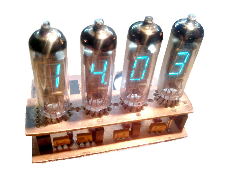
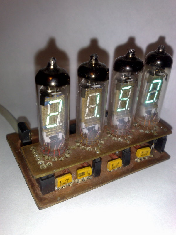
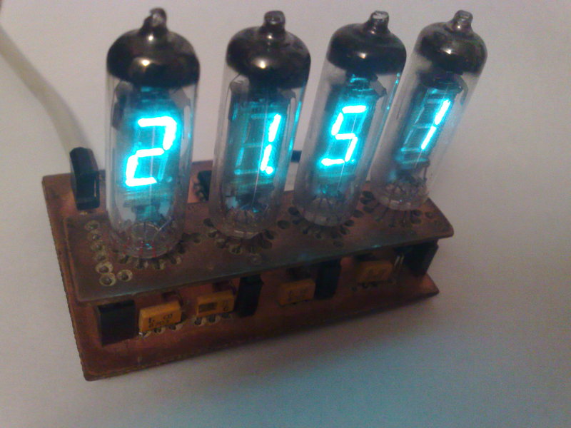
The main role is occupied by gas-discharge indicators. I used IV-6. This is a seven-segment luminescent indicator of the green color of the glow (In the photos you will see a bluish tint of glow, this distorts the color when photographing, due to the presence of ultraviolet rays). Indicator IV-6 is made in a glass flask with flexible leads. Indication is carried out through the side surface of the cylinder. The anodes of the device are made in the form of seven segments and a decimal point.You can use the indicators IV-3A, IV-6, IV-8, IV-11, IV-12 or even IV-17 with minor changes in the scheme.
First of all, I would like to note where you can find lamps, which were produced in 1983.
Mitinsky market. Many and different. In boxes and on the boards. There is room for choice.
Other cities are more difficult, you may get lucky and you will find it in a local radio store. Such indicators are in many domestic calculators.
Can be ordered from Ebay, Yes Yes, Russian indicators at auction. 1 2 3 4 On average $ 12 for 6 pieces.
')
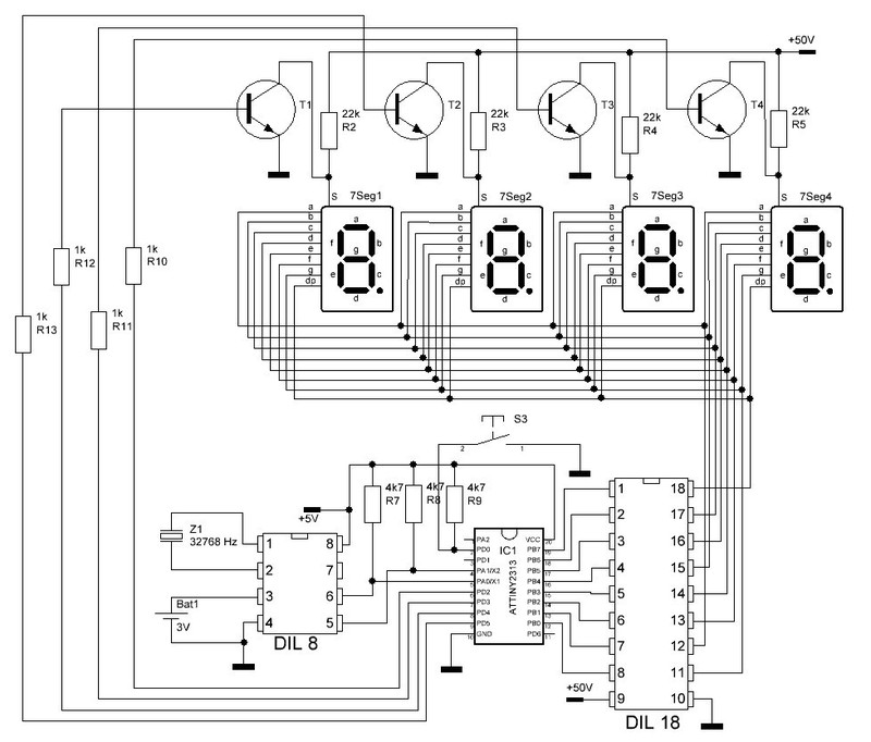
Control
Manages all AtTiny2313 microcontroller and DS1307 real time clock.The clock, in the absence of voltage, goes into battery mode using a CR2032 battery (as on a PC motherboard).
According to the manufacturer, in this mode, they will work and will not get off for 10 years.
The microcontroller is powered by an internal 8 MHz generator. Do not forget to set the fuse bit.
Setting the time is one button. Long retention, incriminating hours, then incriminating minutes. There are no difficulties with this.
Drivers
As keys to segments, I set the KID65783AP. These are 8 "upper" keys. I made a choice in the direction of this chip, only because I had one. This chip is very common in the display boards of washing machines. Nothing prevents to replace it with an analogue. Or tighten the segments with 47KΩ resistors to + 50V, and push the popular ULN2003 to the ground. Just do not forget to invert the output into segments in the program.The display is made dynamic, so the brutal KT315 transistor is added to each digit.
Printed circuit board
The board is made by the LUT method, you can read about this technology from a friend of DIHALT . The clock is made on two boards. What is the reason? I don't even know, I just wanted it that way.Power Supply
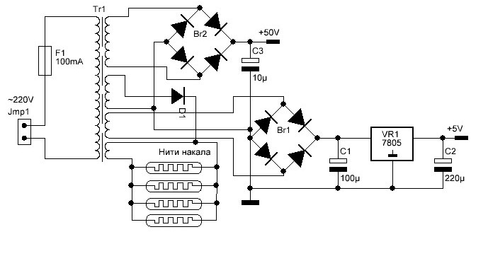
Initially, the transformer was at 50Hz. And contained 4 secondary windings.1 winding - voltage on the grid. After the rectifier and capacitor 50 volts. The more it is, the brighter the segments will be. But not more than 70 volts. Current not less than 20mA
2 winding - to offset the potential of the grid. Approximately 10-15 volts. The smaller it is, the brighter the lights are, but “not included” segments also begin to glow. The current is also 20mA.
3 winding - to power the microcontroller. 7-10 volts. I = 50mA
4 winding - Glow. For four IV-6 lamps it is necessary to set a current of 200mA, which is approximately 1.2 volts. For other lamps, the glow current is different, so consider this point.
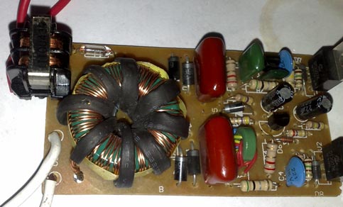
Subsequently, I replaced the pulse transformer. I recommend to take as a basis the power supply for halogen lamps, at the lowest power. You will only have to wind the winding at the desired voltage.
It may turn out that for the heat of 1 revolution a little, and 2 a lot. Then we wind 2 turns and set the current-limiting resistor in series on 1-5 Ohms
Here is a "electronic transformer" with the lid open.
I can offer the option of manufacturing the power supply from a faulty energy saving lamp. I described it here , to whom it became interesting - take a look.
Firmware
The firmware is written in C language in the CodeVisionAvr environment.That's all.
PS The material may contain spelling, punctuation, grammar and other types of errors, including semantic. The author will be grateful for the information about them ©
UPD: Added source github.com
And ready firmware
UPD: At the request of adding a couple more photos.
Source: https://habr.com/ru/post/169879/
All Articles