What is the H-REAP / FlexConnect mode for Cisco wireless access points?
Historically, wireless networks have been built on individually configured access points. For simple tasks (“to distribute Wi-Fi at home”) this approach is still justified, but with the increasing complexity of the network of administrators, the following problems hurt more and more painfully:
What to do?
')
The first step in development was the creation of centralized client authorization mechanisms ( 802.1x ) using a RADIUS server. Each individual access point when trying to connect a client “asks permission” from some external server or service. Usually when moving (roaming) a successfully authorized and working client from point to point, the authorization procedure is repeated anew, which is fraught with the loss of communication for a few seconds.
To eliminate this (and other) disadvantage, the WDS mechanism was invented, allowing several access points to work together. In addition to radio broadcasting functions to increase the coverage area, one selected access point (WDS master) can provide a single authorization center for all clients (and access points) of the WDS domain (using the built-in or external RADIUS server). In this case, roaming clients within the domain does not lead to a full authorization cycle (for the master knows about all the clients on the network). However, the WDS mechanism is not certified by the Wi-Fi Alliance, which often leads to incompatibility of the implementation of solutions based on equipment from different vendors. In addition, all access points are still configured individually.
The next step in the evolution of wireless networks was the advent of wireless controllers . Here, the work with the radio environment (transmission and reception of packets, encryption) is performed by the “stupid” access point, and everything else (centralized management, authorization, transmission of packets to the LAN) is the “smart” controller. Thus, the tasks of scalability, security, manageability, control of roaming and radio environment are successfully solved. With a large number of subscribers and with the use of additional management tools (like Cisco WCS or Juniper RingMaster), geographically distributed networks can be built from hundreds of controllers, thousands of access points and hundreds of thousands of simultaneously operating subscribers.

Consider a typical enterprise network located in a building or neighboring buildings, built on equipment manufactured by Cisco Systems. A “lightweight” access point can be installed anywhere on the network, connected to a normal LAN access port and at the same time provide service for several wireless networks (WLAN) simultaneously, with different security policies: for guests, for staff, for technological devices. The access point creates a tunnel (LWAPP, CAPWAP) to the controller, which transmits information from each client with a network identifier tag). The controller is usually installed in the server room, connected to the local network via the trunk port. Each WLAN network is terminated into a separate virtual network (VLAN), which may also have its own security policies. In this concept, access points are scattered across the building's network, and all wireless clients have one termination point in a wired network. Firewalls, application servers and a gateway to the Internet are installed at this point. Without a controller, you would have to “pull” all VLANs to the server, and in the worst case, “scatter” firewalls throughout the network.
If the wireless user wants to print a document on a printer standing nearby, the data actually goes to the server room via the virtual access point – controller connection, then back over the LAN and another VLAN to the printer. In a high-speed environment (Gigabit Ethernet) this causes no problems. But what if the communication channel is narrow or overloaded? What if you need to provide wireless communication in a remote office via WAN (MPLS, IPSEC)?
There are strict requirements for the quality of the communication channel between the controller and the access point. For Cisco, this is about 100 milliseconds of the allowed delay (round-trip), and the band is 128 kilobits. When the connection with the controller is lost, the “lightweight” access point operating in the normal (“local mode”) mode stops servicing the clients, reboots, and begins to look again for the controller.
Of course, you can install a regular, autonomous access point, with local packet switching. At the same time, roaming, centralized management and security capabilities are lost. Employees traveling to branch offices want to have an equally functioning wireless network everywhere, without reconfiguration.
You can buy and install a separate small wireless controller in each branch, but this is a costly path.
As an alternative to a wireless solution from Cisco, a “semi-autonomous” mode of operation of access points was proposed. In general, an access point connected to the controller may be in the following modes of operation:
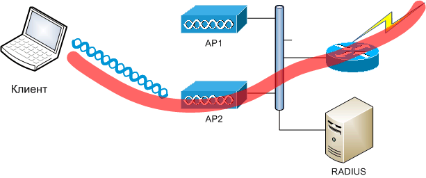
H-REAP (Hybrid Remote-Edge Access Point), also known as FlexConnect , allows the access point to be controlled by the controller, but continue to work if the connection with it is lost . Wireless networks are connected to the local network either still (via the controller) or locally. Similarly, authorization is performed. Let's see how it is configured and how it works (using the example of the WLC4402 controller and the LAP-1131 points).
Changing the mode of operation leads to a reset of the access point, and its subsequent connection to the controller in a new mode.

Recall that when setting up an individual wireless network (WLAN, SSID) you specify:
If an access point is installed in a remote branch office and provides subscribers with a “corporate WLAN”, subscriber authorization takes place on the central RADIUS server, and all traffic is sent to the central office controller. This mode is called “central authentication, central switching” and is the only valid for access points in local mode.
In the wireless network settings (WLAN, SSID), you can specify additional parameters that have an impact on its service from a point in the H-REAP mode (they do not affect the operation in local mode).
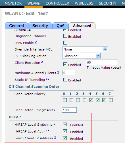
The first parameter (H-REAP Local Switching) enables packet switching from this network to the LAN locally, directly by the access point, without being sent to the controller.
The second parameter allows local (at the access point itself) client authentication (via a stored PSK key, through a local user database, through a locally configured RADIUS server).
The third parameter causes the access point to determine the IP addresses of the connected clients (usually the controller itself does this).
The H-REAP access point can be in the following states: connected (the controller is available) and standalone (the controller is unavailable). Each of the served wireless networks is in the following states:
central authentication, central switching - the same mode as for the normal (local) point in the connected state
central authentication, local switching - central authorization, traffic switching locally - only in the connected state
local authentication, local switching — local authorization and local traffic switching. If the controller is available (connected), it receives from the access point some limited information about the clients connected to it. If not available (standalone), new customers can connect and be serviced.
authentication down, switch down - if local switching is turned off for this network and the controller is unavailable, authorization fails, packets do not go
authentication down, local switching — if the controller is not available , local switching is on for local switching and local auth is turned off, new clients are not connected, but old ones continue to work.
I hope you noticed that when configuring the wireless network on the controller, you need to specify which wired network (VLAN) the traffic is terminated to. By default, the H-REAP access point is connected to the access port of the switch (access port, no tags). When several wireless networks are operating, all their traffic is sent to the same port, without tags.

It is highly desirable to configure the switch port to which the H-REAP access point is connected to the trunk port (by turning on the “VLAN Support” checkbox) and create a correspondence between the locally switched WLAN and the local VLAN of the switch. Attention: this correspondence may differ from what is written on the controller. This is done in the additional tab “H-REAP” of the access point parameters:

In this case, you need to register the corresponding VLAN number on the switch in the number allowed in the trunk.
It is curious that with this setting, the access point receives from the controller a special piece of the configuration file (you never know, the controller can also be "lost"), which can be viewed:
Finally, you need to deal with local user authorization. For shared keys, everything is simple - the PSK key is transmitted to the access point, and it does not need anything else to authorize clients. In the case of 802.1x for local authorization, you can use either the mini-RADIUS server (+ local user base) built into the access point itself, or you can specify external RADIUS servers (not necessarily installed in the center of the network). For example, you can deploy your FreeRadius, or a server built into Windows IAS / NPS locally in a branch office, for example, for authorization via EAP / MS-CHAPv2 and a local copy of Active Directory.
These functions are configured through the so-called H-REAP Groups:
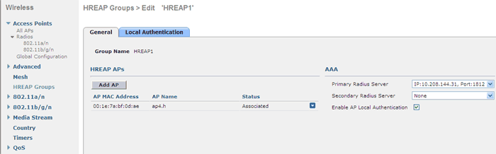
You add the access points on the H-REAP controller to the group, set the total set of RADIUS servers for the group (do not forget to allow access points to the RADIUS server), you can also enable local authorization using the access point database itself. In this case, you can specify a set of allowed users (username / password) and authorization protocols (EAP-FAST and LEAP are supported).

To summarize: the H-REAP mode of Cisco wireless points allows you to install them at branch offices without a local controller (saving!). Points use the central controller for receiving settings, management and monitoring. Local wireless connections are quietly experiencing the loss of communication between the center and the branch (drop of the WAN channel). You can use local authorization and local packet switching, roaming clients between points within the branch. If you happen to configure the H-REAP mode, I highly recommend you carefully study the manufacturer's documentation (to which the author has nothing to do).
- scalability (need to support a large number of users)
- security (need to have the same settings throughout the network)
- manageability (the need to centrally find out at which point this subscriber)
- roaming (even more important for voice / video applications)
- radio resource monitoring (overlapping frequency bands)
What to do?
')
The first step in development was the creation of centralized client authorization mechanisms ( 802.1x ) using a RADIUS server. Each individual access point when trying to connect a client “asks permission” from some external server or service. Usually when moving (roaming) a successfully authorized and working client from point to point, the authorization procedure is repeated anew, which is fraught with the loss of communication for a few seconds.
To eliminate this (and other) disadvantage, the WDS mechanism was invented, allowing several access points to work together. In addition to radio broadcasting functions to increase the coverage area, one selected access point (WDS master) can provide a single authorization center for all clients (and access points) of the WDS domain (using the built-in or external RADIUS server). In this case, roaming clients within the domain does not lead to a full authorization cycle (for the master knows about all the clients on the network). However, the WDS mechanism is not certified by the Wi-Fi Alliance, which often leads to incompatibility of the implementation of solutions based on equipment from different vendors. In addition, all access points are still configured individually.
The next step in the evolution of wireless networks was the advent of wireless controllers . Here, the work with the radio environment (transmission and reception of packets, encryption) is performed by the “stupid” access point, and everything else (centralized management, authorization, transmission of packets to the LAN) is the “smart” controller. Thus, the tasks of scalability, security, manageability, control of roaming and radio environment are successfully solved. With a large number of subscribers and with the use of additional management tools (like Cisco WCS or Juniper RingMaster), geographically distributed networks can be built from hundreds of controllers, thousands of access points and hundreds of thousands of simultaneously operating subscribers.
Consider a typical enterprise network located in a building or neighboring buildings, built on equipment manufactured by Cisco Systems. A “lightweight” access point can be installed anywhere on the network, connected to a normal LAN access port and at the same time provide service for several wireless networks (WLAN) simultaneously, with different security policies: for guests, for staff, for technological devices. The access point creates a tunnel (LWAPP, CAPWAP) to the controller, which transmits information from each client with a network identifier tag). The controller is usually installed in the server room, connected to the local network via the trunk port. Each WLAN network is terminated into a separate virtual network (VLAN), which may also have its own security policies. In this concept, access points are scattered across the building's network, and all wireless clients have one termination point in a wired network. Firewalls, application servers and a gateway to the Internet are installed at this point. Without a controller, you would have to “pull” all VLANs to the server, and in the worst case, “scatter” firewalls throughout the network.
If the wireless user wants to print a document on a printer standing nearby, the data actually goes to the server room via the virtual access point – controller connection, then back over the LAN and another VLAN to the printer. In a high-speed environment (Gigabit Ethernet) this causes no problems. But what if the communication channel is narrow or overloaded? What if you need to provide wireless communication in a remote office via WAN (MPLS, IPSEC)?
There are strict requirements for the quality of the communication channel between the controller and the access point. For Cisco, this is about 100 milliseconds of the allowed delay (round-trip), and the band is 128 kilobits. When the connection with the controller is lost, the “lightweight” access point operating in the normal (“local mode”) mode stops servicing the clients, reboots, and begins to look again for the controller.
Of course, you can install a regular, autonomous access point, with local packet switching. At the same time, roaming, centralized management and security capabilities are lost. Employees traveling to branch offices want to have an equally functioning wireless network everywhere, without reconfiguration.
You can buy and install a separate small wireless controller in each branch, but this is a costly path.
As an alternative to a wireless solution from Cisco, a “semi-autonomous” mode of operation of access points was proposed. In general, an access point connected to the controller may be in the following modes of operation:
- Local - the traditional mode (by default), when a point is considered “locally connected” to the controller, and transmits all traffic through it.
- H-REAP - the mode of “remote” or semi-autonomous work, as discussed below
- Monitor - the point does not serve clients, but scans the radio medium. Required to more accurately determine the coordinates of the client device, which is important in some mobile tasks
- Rogue detector - the point does not serve customers and turns off the radio. Instead, the point reports to the controller about MAC addresses locally defined on the Ethernet port, which allows you to search for “harmful” access points that have been illegally installed on your network.
- Sniffer - the point "listens" to the packets on the radio and transmits them for further analysis to a computer with AiroPeek or Wireshark
- Bridge - the point works in the wireless bridge mode, for the organization of MESH-networks
- SE-Connect - a point allows you to work in the spectrum analyzer mode (with Cisco Spectrum Expert software configured), only compatible models 3500 and 3600)
H-REAP (Hybrid Remote-Edge Access Point), also known as FlexConnect , allows the access point to be controlled by the controller, but continue to work if the connection with it is lost . Wireless networks are connected to the local network either still (via the controller) or locally. Similarly, authorization is performed. Let's see how it is configured and how it works (using the example of the WLC4402 controller and the LAP-1131 points).
Changing the mode of operation leads to a reset of the access point, and its subsequent connection to the controller in a new mode.
Recall that when setting up an individual wireless network (WLAN, SSID) you specify:
- Network name
- Security settings (network key for WPA / WPA2 PSK or 802.1x authorization requirement for WPA / WPA2 Enterprise . In the second case, you need to configure the controller to communicate with the RADIUS server
- The name of the local dynamic interface of the controller (VLAN number, respectively) to which the controller sends packets for this wireless network.
If an access point is installed in a remote branch office and provides subscribers with a “corporate WLAN”, subscriber authorization takes place on the central RADIUS server, and all traffic is sent to the central office controller. This mode is called “central authentication, central switching” and is the only valid for access points in local mode.
In the wireless network settings (WLAN, SSID), you can specify additional parameters that have an impact on its service from a point in the H-REAP mode (they do not affect the operation in local mode).
The first parameter (H-REAP Local Switching) enables packet switching from this network to the LAN locally, directly by the access point, without being sent to the controller.
The second parameter allows local (at the access point itself) client authentication (via a stored PSK key, through a local user database, through a locally configured RADIUS server).
The third parameter causes the access point to determine the IP addresses of the connected clients (usually the controller itself does this).
The H-REAP access point can be in the following states: connected (the controller is available) and standalone (the controller is unavailable). Each of the served wireless networks is in the following states:
central authentication, central switching - the same mode as for the normal (local) point in the connected state
central authentication, local switching - central authorization, traffic switching locally - only in the connected state
local authentication, local switching — local authorization and local traffic switching. If the controller is available (connected), it receives from the access point some limited information about the clients connected to it. If not available (standalone), new customers can connect and be serviced.
authentication down, switch down - if local switching is turned off for this network and the controller is unavailable, authorization fails, packets do not go
authentication down, local switching — if the controller is not available , local switching is on for local switching and local auth is turned off, new clients are not connected, but old ones continue to work.
I hope you noticed that when configuring the wireless network on the controller, you need to specify which wired network (VLAN) the traffic is terminated to. By default, the H-REAP access point is connected to the access port of the switch (access port, no tags). When several wireless networks are operating, all their traffic is sent to the same port, without tags.
It is highly desirable to configure the switch port to which the H-REAP access point is connected to the trunk port (by turning on the “VLAN Support” checkbox) and create a correspondence between the locally switched WLAN and the local VLAN of the switch. Attention: this correspondence may differ from what is written on the controller. This is done in the additional tab “H-REAP” of the access point parameters:
In this case, you need to register the corresponding VLAN number on the switch in the number allowed in the trunk.
It is curious that with this setting, the access point receives from the controller a special piece of the configuration file (you never know, the controller can also be "lost"), which can be viewed:
 ap4.h # sh runn brief
 ...
 !  network number 4 is wrapped in VLAN 406
 dot11 vlan-name 004 vlan 406
 ...
 interface Dot11Radio0.4
  encapsulation dot1Q 4!  number 4 means nothing
  no ip route-cache
  bridge-group 255!  and the bridge group number means
  bridge-group 255 subscriber-loop-control
  bridge-group 255 block-unknown-source
  no bridge-group 255 source-learning
  no bridge-group 255 unicast-flooding
  bridge-group 255 spanning-disabled
 !
 interface Dot11Radio0.17
  encapsulation dot1Q 17 native
  no ip route-cache
  bridge-group 1
  bridge-group 1 subscriber-loop-control
  bridge-group 1 block-unknown-source
  no bridge-group 1 source-learning
  no bridge-group 1 unicast-flooding
  bridge-group 1 spanning-disabled
 !
 interface FastEthernet0.1
  encapsulation dot1Q 1 native
  ip address 10.20.1.223 255.255.252.0
  no ip route-cache
  bridge-group 1!  this bridge group defines the connection of the point itself in the native vlan
  no bridge-group 1 source-learning
  bridge-group 1 spanning-disabled
 !
 interface FastEthernet0.406
  encapsulation dot1Q 406
  no ip route-cache
  bridge-group 255!  this bridge group defines the connection of vlan 406
  no bridge-group 255 source-learning
  bridge-group 255 spanning-disabled
 ...
 radius-server local
   no authentication eapfast
   no authentication leap
   no authentication mac
   nas 10.20.1.223 key 7 ……
   group hreap
   !
 !
Finally, you need to deal with local user authorization. For shared keys, everything is simple - the PSK key is transmitted to the access point, and it does not need anything else to authorize clients. In the case of 802.1x for local authorization, you can use either the mini-RADIUS server (+ local user base) built into the access point itself, or you can specify external RADIUS servers (not necessarily installed in the center of the network). For example, you can deploy your FreeRadius, or a server built into Windows IAS / NPS locally in a branch office, for example, for authorization via EAP / MS-CHAPv2 and a local copy of Active Directory.
These functions are configured through the so-called H-REAP Groups:
You add the access points on the H-REAP controller to the group, set the total set of RADIUS servers for the group (do not forget to allow access points to the RADIUS server), you can also enable local authorization using the access point database itself. In this case, you can specify a set of allowed users (username / password) and authorization protocols (EAP-FAST and LEAP are supported).
To summarize: the H-REAP mode of Cisco wireless points allows you to install them at branch offices without a local controller (saving!). Points use the central controller for receiving settings, management and monitoring. Local wireless connections are quietly experiencing the loss of communication between the center and the branch (drop of the WAN channel). You can use local authorization and local packet switching, roaming clients between points within the branch. If you happen to configure the H-REAP mode, I highly recommend you carefully study the manufacturer's documentation (to which the author has nothing to do).
Source: https://habr.com/ru/post/169511/
All Articles