Display the electricity meter on the Internet
In the article I will talk about how to obtain data on power from the electric meter and bring them to the Internet.
I’ll say right away that despite the fact that the meter is digital and has digital interfaces for communicating with external control equipment, I do not use them (why - below).
How it all began
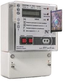
At a certain moment, the power engineers changed our usual mechanical electricity meter to a digital one. Immediately struck by the ability to display the counter current capacity. There was a desire to somehow get this value from the counter. In addition, the new meter has a threshold of maximum allowable power (5 kW), at which it turns off the electricity in the apartment, and it usually happens completely suddenly. So I wanted to make a device capable of detecting that the power is close to the threshold, and to signal this in order to be able to disconnect part of the loads.
How can I get power data
- Since the counter is digital, the first thing that comes to mind is to use the interfaces it contains. It follows from the instruction to the meter that it has an RS-485 interface, a test output and an optical port on the front panel. However, they will not be able to use them - the wired interfaces are under a sealed cover, and you cannot get there, the optoport does not show activity. If the calibration output can also be used, then the digital interfaces are not documented anywhere, and most likely are protected by a password.
- Do not use a meter at all, and measure the amount of current in the phase conductor. This method is used here: habrahabr.ru/post/168783 . However, for such measurements a special sensor is needed, which still needs to be taken somewhere. In addition, the sensor is analog, and where there is an analog signal, there are pickups, which you can catch a lot in the electrical panel. To accurately measure the power you need to know the value of the mains voltage, which also creates certain problems.
- Another method that I used is to measure the period of flashes of the LED located on the front panel of the meter. This LED is directly connected to a microcircuit measuring current flowing through a meter. As I understand it, this LED is associated with the aforementioned calibration output. Next to the LED is written the so-called gear ratio : 2000 imp / kWh, knowing that with a sufficiently accurate measurement of the flash period, it is easy to determine the power consumption.
Technical implementation
All signal processing from the photo sensor is carried out by a very simple device on the STM8S105 microcontroller. STM8 was chosen because of its presence, and also since 3 outputs are enough for its programming.
Detecting LED flashes is easy - it is enough to use a phototransistor as a photosensor, and due to the fact that the flashes are bright and the phototransistor is quite sensitive, the signal can be fed directly to the controller's digital outputs - the signal amplitude during the flash is close to 0, and the rest of the time close to the supply voltage. To protect against external illumination, the phototransistor should be covered with an opaque cover and pressed tightly against the meter.
')
The alarm about exceeding the permissible power threshold is also implemented quite simply: next to the device there is a transmitter-button from a wireless call connected to the controller via an optocoupler. The call receiver itself lies in the room next to the shield, and when the power is exceeded, the call starts beeping.
The data from the controller must be somehow transferred to the device that will process them, in this case it is the WL-500gp router. Wireless connections could be used, but there are several concrete walls and a steel door between the router and the controller. Also in this case, the controller will need to provide power, and trying to connect the power supply to the power wiring in the switchboard would not be desirable.
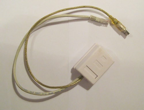
More simple is the wired connection. Since the data must be transferred to the router, you can use the already laid cable connecting the router to the provider - this cable passes through the electrical panel. The cable for networking is used only 4 cores of 8, so the remaining 4 can be used for their needs.
One pair of wires can be used to transfer power to the controller, the other - to transfer data to the router. However, I wanted to realize the transfer of data and power for only one pair of wires. For this, I used a digital current loop.
About current loop can be read in Wikipedia , as well as here .
In this case, the device consists of two parts - the receiver, located next to the router, and the transmitter, which contains a microcontroller. The transmitter contains a current source (I use the NSI45020, designed to power the LEDs) and a transistor connected in series with it.

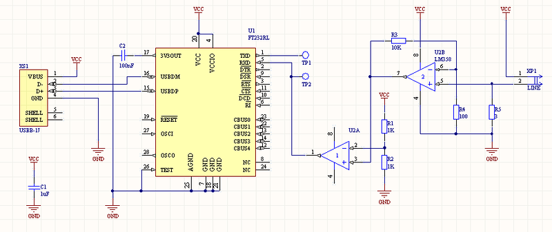
The scheme of the current loop.
When a high-level voltage is applied to the base of the transistor, it opens, and a certain current begins to flow through the communication line. As a result, a voltage drop occurs on the current-measuring resistor (3 ohms), which is amplified by the operational amplifier. The increased voltage is applied to the comparator, and if it is greater than a certain threshold (Vref), then a high voltage level is set at the output of the comparator. In the absence of current (more precisely, at its small value, since the controller always consumes current), the voltage drop across the resistor is small, and a low voltage level is set at the comparator output.
The power supply of the whole structure is a router, the voltage of 5 V from which is fed to the receiver (inputs on the left in the diagram) and passes through the line with almost no changes - since the currents are low and the line is short, the voltage drop across the resistor and wires is small enough. Further, this voltage can be used to power the microcontroller (the outputs on the right of the diagram).
To transfer data from the microcontroller, its UART output is connected to the base of the transistor, and the comparator output is connected to the input of the UART converter - USB. The data transfer rate is 1200 bps. This ensures reliable data transmission, and at such a small speed, even a short burst transmission is visible by the flashing LED.
Complete receiver and transmitter circuits
Transmitter
Receiver
Transmitter
Receiver
The receiver and transmitter boards were made by LUT method on one board, after assembly and debugging the board was cut:

The receiver is installed inside a regular RJ-45 outlet, the cable going into the shield is inserted into the outlet, the cable from the outlet is inserted into the router.
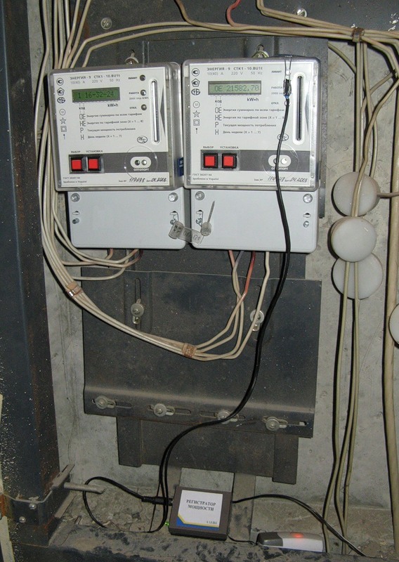
The transmitter is installed in a small box and placed in a shield along with a bell button:
Data processing
The microcontroller installed in the receiver measures the period of the LED flashes on the electric meter and calculates power from it. This value is constantly compared with the threshold of the maximum allowable power, and when it is exceeded, the controller includes a bell.
Every 10 seconds, the controller transmits the last measured amount of power via UART to the router. Here a certain problem arises - at low power consumption, the LED on the counter flashes with a period longer than 10 seconds. In this case, the power is sent to the router - 0.
I installed the Python interpreter on the router, and wrote a script that processes the data from the receiver, organizes the simplest local web server, and every 2 minutes sends the average power to cosm.com.
The data on the web server is updated when receiving data from the receiver - every 10 seconds. When calculating the average power, the script takes into account the fact that the real power cannot be equal to 0 - when a new power value is obtained that is not equal to zero, all previous zero values are replaced with a new value.
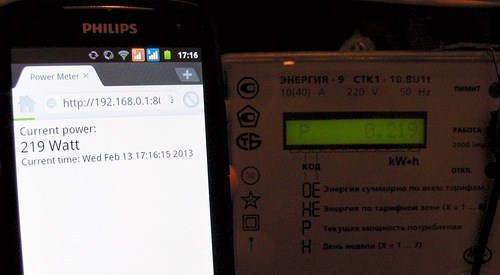
This is the server's web page, which is open on the phone:
Charts from Cosm.com


Concerning the price of the device:
STM8 - 60 rubles
FT232 - 180 rubles, although you can use the cheaper PL2303.
The rest of the harness - around 50 rubles.
The PCB is self-made, you can order from the Chinese for 1 dollar (if you order 10 pieces).
Shells - were already available, the RJ-45 socket costs 50 rubles.
So the price of the entire device is not more than 400 rubles.
Cheapness is achieved due to the fact that the device is wired.
Source code and firmware for controller and Python script for router
Source: https://habr.com/ru/post/169069/
All Articles