A machine on a controller with the .NET Micro Framework, controlled by an accelerometer Android device
A simple project describing the manufacture of 4WD cars with control from an Android device via a Bluetooth channel. The machine is controlled using an accelerometer, by tilting the tablet / smartphone. Video of work, see the end of the article. All source code is attached.
Development tools: Java / Eclipse for Android and .NET Micro Framework / Visual C # Express for the microcontroller.
Introduction
I am not a supporter of various clever smartphones, iPads and others. Cool technological gadgets. Since 2001, I have only a second phone: the Samsung B2700 (the first was the Siemens C55, still working with my grandmother). But by the nature of my business, I needed a device to access via SSH to the servers, and also to the Web interface, when I was traveling. In this connection, one of the cheapest Chinese Android tablets was bought: Ainol Aurora. It worked quite normally, and the web, and ssh, the console, and even the ftp client, in general, performed their functions at 100%. But I only needed him on trips, the rest of the time he was stupidly lying off at home, because I do not play, I cannot read from the screen, for surfing the web there are stationary PCs. Well, I decided to dig deeper, adapt it for something else. The first idea was to make a smart home, but part of the system was already functioning, and the repair was completed recently, new devices, cables, power connections, etc. did not want to be built. Therefore, I rejected the idea, but I bought a Seeeduino ADK Main Board for the sake of sporting interest and played a little with transferring information via a USB connection (Open Accessory and MicroBridge). In the process, I found out that even Android 4.0.3 is on the tablet, this does not mean that it supports Open Accessory. Therefore, it was played with the MicroBridge mode, data exchange was successful, but still there were some strange moments to me ...
')
In the end, I came to the 2nd idea: to connect the device via radio. Wi-Fi modules are expensive, and I wanted to start with something simpler, so I bought a couple of Serial Bluetooth modules on ebay at a price of $ 6-7 apiece. As a real task, I decided to make a controlled machine with Android. At that time, there were already quite a few similar projects on the foreign Internet, but for the most part the device was controlled from the standard Bluetooth Terminal program by entering commands from the keyboard. This is of course all good, but very uncomfortable. We came across projects with our own Android software, but as a rule, management was carried out using on-screen keys. I wanted to come up with something original, but because almost all tablets are equipped with a built-in accelerometer, it was decided to use it. There was no coding experience for Android, just as I had practically no business with modern OOP languages. But I had to deal a little with Java and the features of writing applications for Android. And in this article I want to describe the manufacture of a simple ru-bluetooth typewriter, controlled by an Android device.
To implement our plans you will need:
1. Android device
2. Controller (PWM, UART)
3. Bluetooth module
4. Engine Driver
5. Platform for typewriter
I think that the majority of visitors to Habr are programmers and people who are somehow connected with IT. Therefore, they will be of little interest in the options where PIC, STM32, Arduino, etc. will be used as a controller. That is why I decided to use the FEZ Panda II controller lying around idle with the .NET Micro Framework. Software development for this controller is carried out in the Visual C # Express environment, i.e. For most programmers, this will be a familiar toolkit, although .NET is truncated there and there are no many functions.
But first things first. So, as mentioned above, an Android tablet or smartphone is required, preferably with an accelerometer (without it, they probably are not being released without it now).
Controller - any under the .NET Micro Framework. Those. Suit Netduino, GHI Electronics motherboards, etc. I used FEZ Panda II:

The Chinese UART module HC-06 is used as the Bluetooth module. Any Serial Bluetooth will do. It is better to take with the pin pins, so as not to have to be soldered, because the distance between the leads is very small. The cost of such a module on AliExpress / eBay averages $ 5-10.

As a driver, I used a shawl with an L298N microcircuit, which is a dual bridge motor driver and is designed to control DC and stepper motors. Issue price 4-5 $.

For the platform of the machine, you can use anything with 2 or 4 DC motors. I bought on eBay a ready-made 4WD chassis for DIY projects with 4 DC motors.

Well, in addition, we needed batteries, temusadka, clamps, connecting wires, etc.
Chassis assembly
4WD platform from DFRobot comes unassembled:

The assembly is not complicated, the only thing that the wheels are very tightly worn on the axle. He worked a little katerom and got up like relatives.
In the compartment with the motors, I placed the L298N board, connected them to it, and brought out 6 wires: 4 for control, GND and power.

I will not describe the detailed assembly of the 4WD platform, anyway everyone will have their own, and even if they have a 4WD chassis from DFRobot, they will have their own corrections depending on the equipment and materials at home.
Bluetooth module I used Chinese HC-06. I recommend to take immediately with the pin leads, so as not to mess with soldering.
Required pins of the HC-06 module:
UART_TX (pin 1), UART_RX (pin 2)
3.3V (pin 12) - 3.3V power supply.
GND (pin 13) is common.
PIO1 (pin 24) - operating mode indicator. If the connection is not established, then the LED flashes, if established, it is constantly on.
On the L298N board, it is necessary to bring 5 wires from the controller: GND (Common), IN1, IN2, IN3, IN4 - motor control inputs (PWM and direction of rotation for the left engine and the same for the right one).
The DC motor is powered by Li-Po 3.7V 1100 mA batteries. The controller is powered by a separate 3.7V battery (although 5V is required, but it works fine from 3.7V). The power supply of the Bluetooth module is taken from the FEZ board.

There is a big mess in the wires due to the fact that before the project was going to the STM32 and was disassembled specifically for implementation with the FEZ Panda II controller. In the future, the machine will again be on the STM32 and Arduino with some improvements. But this is a topic for another article, perhaps ...
The wiring diagram is as follows:

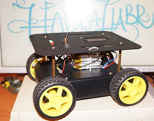
Fez FEZ to the platform attached with 2-sided tape:

Next, everything was assembled and connected. It turned out like this:

Software
So, in the application for Android, I implemented 3 ways to control:
1. Accelerometer - by tilting the device
2. Buttons - 4 buttons are drawn on the smartphone screen: forward, backward, turn left, turn right.
3. Touch-control. I saw this method in the game Death Rally, I wanted to try to implement it. Honestly, it was not very convenient, but I left it as it is.
4. 02.15.2013 in the software added a new type of control "virtual steering wheel"
All calculations occur in the Android application. The controller receives ready data for PWM, rotation directions and commands for working with flash memory. So It turned out a universal application with flexible settings that can fit different types of controllers, in different PWM values, etc. Actually, what has already been partially done: this project has already been implemented on STM32, Arduino and FEZ Panda II. In the near future there are plans to implement for other platforms: MSP430, PIC, etc.
An example of a command transmitted via Bluetooth:
L-60 \ rR-100 \ r
The symbol L means commands for the left motor, the minus sign is the rotation back, 60 is the PWM value. R is for the right motor, 100 is the PWM value (maximum value for FEZ Panda II). For Arduino, for example, the maximum PWM value is 255, it can be set in the Android application settings. At this command, the machine will move back, because the left wheels will rotate a little slower than the right ones, but it will turn slightly to the left. As you can see, this method of control is more suitable for a tracked platform.
Fw1035 \ t - the command to write to the microcontroller's flash memory the timeout value (after what time the machine stops when the connection is lost or the command is not received). The first digit 1 means the timeout is on (respectively, 0 is off). To get the value in seconds, it is necessary to divide 035 by 10, i.e. in this case, the timeout will be 3.5 seconds. Accordingly, the range of values is from 0.1 to 99.9 seconds.
To the machine you can pick up a lot of additional channels: lights, signal, pyro cartridge and much more. Team to add. Channel: H1 \ r - where 1 is included. Accordingly, if you submit 0, then turn off. In the presented software, only 1 additional channel is implemented, however, by analogy with it, you can make as many as you like.
By the way, command symbols can also be set in the Android application settings. The settings themselves are set from the main activation, here is their screenshot:

Please note that the MAC address of the Bluetooth module is set in the application settings. You can find it using any program to work with Bluetooth, for example using Bluetooth Terminal or Bluetooth Chat. Of course, it would be more convenient to do a device search and pairing in the software itself, but honestly, I didn’t have enough intelligence and experience, I was busy with this question of day 2, I read forums and the Stack Exchange, but it didn’t work out. Maybe in the future I will return to this issue.
I will not give the source code of the Android application, since it is large enough. Who cares, at the bottom of the article is a complete project for Eclipse. I note only that the application uses the main activity with the menu buttons and settings, as well as 4 additional activities - 3 for management and one for working with the microcontroller memory.

I carried out work with Bluetooth in a separate class cBluetooth. To receive data from BT, a separate thread is created, which, in the case of receiving data, places them in the Handler message queue. Further, in the main thread, these messages are processed and captions are displayed in the activation and other actions are implemented.
Source for .NET Micro Framework:
using System; using System.IO.Ports; using System.Threading; using System.Text; using Microsoft.SPOT; using Microsoft.SPOT.Hardware; using GHIElectronics.NETMF.Hardware; using GHIElectronics.NETMF.FEZ; namespace CxemCAR { public class Program { public const char cmdL = 'L'; // UART public const char cmdR = 'R'; // UART public const char cmdH = 'H'; // UART . 1 ( Horn) public const char cmdF = 'F'; // UART EEPROM public const char cmdr = 'r'; // UART EEPROM () public const char cmdw = 'w'; // UART EEPROM () //public const int t_TOut = 2500; // - , static int sw_autoOFF; static int autoOFF = 2500; static byte[] storage = new byte[InternalFlashStorage.Size]; // FLASH static OutputPort MotorL_d = new OutputPort((Cpu.Pin)FEZ_Pin.Digital.Di4, false); // 1 static OutputPort MotorR_d = new OutputPort((Cpu.Pin)FEZ_Pin.Digital.Di7, false); // 2 static OutputPort Channel1 = new OutputPort((Cpu.Pin)FEZ_Pin.Digital.Di8, false); // . 1 static PWM MotorL = new PWM((PWM.Pin)FEZ_Pin.PWM.Di5); // 1 () static PWM MotorR = new PWM((PWM.Pin)FEZ_Pin.PWM.Di6); // 2 () static SerialPort UART1 = new SerialPort("COM1", 9600); // UART1 ( COM1) static Timer timerTO; // public static void Main() { byte[] L_Data = new byte[4]; // L byte L_index = 0; // byte[] R_Data = new byte[4]; // R byte R_index = 0; // byte[] H_Data = new byte[1]; // . byte H_index = 0; // byte[] F_Data = new byte[8]; // EEPROM byte F_index = 0; char command = ' '; // : R, L, H, F int i_tmp_L = 0; int i_tmp_R = 0; int i_tmp_H = 0; byte[] incomingByte = new byte[1]; // UART UART1.Open(); UART1.Flush(); timerTO = new Timer(new TimerCallback(TimeOut), null, autoOFF, autoOFF); // timer_init(); // while (true) { int read_count = UART1.Read(incomingByte, 0, 1); // if (read_count > 0) // ? { if (incomingByte[0] == cmdL) // L { command = cmdL; // Array.Clear(L_Data, 0, L_Data.Length); // L_index = 0; // } else if (incomingByte[0] == cmdR) // R { command = cmdR; // Array.Clear(R_Data, 0, R_Data.Length); // R_index = 0; // } else if (incomingByte[0] == cmdH) // . 1 { command = cmdH; // Array.Clear(H_Data, 0, H_Data.Length); // H_index = 0; // } else if (incomingByte[0] == cmdF) // . 1 { command = cmdF; // Array.Clear(F_Data, 0, F_Data.Length); // F_index = 0; // } else if (incomingByte[0] == '\r') command = 'e'; // else if (incomingByte[0] == '\t') command = 't'; // if (command == cmdL && incomingByte[0] != cmdL) { if (ValidData(incomingByte[0])) { L_Data[L_index] = incomingByte[0]; // if (L_index < (L_Data.Length - 1)) L_index++; // } } else if (command == cmdR && incomingByte[0] != cmdR) { if (ValidData(incomingByte[0])) { R_Data[R_index] = incomingByte[0]; if (R_index < (R_Data.Length - 1)) R_index++; } } else if (command == cmdH && incomingByte[0] != cmdH) { if (ValidData(incomingByte[0])) { H_Data[H_index] = incomingByte[0]; if (H_index < (H_Data.Length - 1)) H_index++; } } else if (command == cmdF && incomingByte[0] != cmdF) { F_Data[F_index] = incomingByte[0]; if (F_index < (F_Data.Length - 1)) F_index++; } else if (command == 'e') // { timerTO.Dispose(); // string tmp_L = new string(System.Text.UTF8Encoding.UTF8.GetChars(L_Data)); // string tmp_R = new string(System.Text.UTF8Encoding.UTF8.GetChars(R_Data)); string tmp_H = new string(System.Text.UTF8Encoding.UTF8.GetChars(H_Data)); try { if (tmp_L != null) i_tmp_L = int.Parse(tmp_L); // int if (tmp_R != null) i_tmp_R = int.Parse(tmp_R); if (tmp_H != null) i_tmp_H = int.Parse(tmp_H); } catch { Debug.Print("Error: convert String to Integer"); } if (i_tmp_L > 100) i_tmp_L = 100; else if (i_tmp_L < -100) i_tmp_L = -100; if (i_tmp_R > 100) i_tmp_R = 100; else if (i_tmp_R < -100) i_tmp_R = -100; Control4WD(i_tmp_L, i_tmp_R, i_tmp_H); timerTO.Change(autoOFF, autoOFF); // } else if (command == 't') // { Flash_Op(F_Data[0], F_Data[1], F_Data[2], F_Data[3], F_Data[4]); } } } } static void Flash_Op(byte FCMD, byte z1, byte z2, byte z3, byte z4) { if (FCMD == cmdr && sw_autoOFF != 255) // EEPROM { byte[] buffer = Encoding.UTF8.GetBytes("FData:"); // UART UART1.Write(buffer, 0, buffer.Length); // UART byte[] buffer2 = new byte[4] { storage[0], storage[1], storage[2], storage[3] }; UART1.Write(buffer2, 0, buffer2.Length); byte[] buffer3 = Encoding.UTF8.GetBytes("\r\n"); UART1.Write(buffer3, 0, buffer3.Length); } else if (FCMD == cmdw) // EEPROM { byte[] varToSave = new byte[InternalFlashStorage.Size]; varToSave[0] = z1; varToSave[1] = z2; varToSave[2] = z3; varToSave[3] = z4; InternalFlashStorage.Write(varToSave); // FLASH timer_init(); // byte[] buffer2 = Encoding.UTF8.GetBytes("FWOK\r\n"); // UART UART1.Write(buffer2, 0, buffer2.Length); // , } } static void timer_init() { InternalFlashStorage.Read(storage); // FLASH sw_autoOFF = storage[0]; if(sw_autoOFF == '1'){ // byte[] var_Data= new byte[3]; var_Data[0] = storage[1]; var_Data[1] = storage[2]; var_Data[2] = storage[3]; string tmp_autoOFF = new string(System.Text.UTF8Encoding.UTF8.GetChars(var_Data)); autoOFF = int.Parse(tmp_autoOFF)*100; timerTO.Change(autoOFF, autoOFF); // } else if(sw_autoOFF == '0'){ timerTO.Dispose(); // } Debug.Print("Timer Init" + autoOFF.ToString()); } static void TimeOut(object o) { //Debug.Print(DateTime.Now.ToString()); Control4WD(0, 0, 0); // } public static void Control4WD(int mLeft, int mRight, int Horn) { bool directionL, directionR; // L298N int valueL, valueR; // M1, M2 (0-100) if (mLeft > 0) { valueL = mLeft; directionL = false; } else if (mLeft < 0) { valueL = 100 - System.Math.Abs(mLeft); directionL = true; } else { directionL = false; valueL = 0; } if (mRight > 0) { valueR = mRight; directionR = false; } else if (mRight < 0) { valueR = 100 - System.Math.Abs(mRight); directionR = true; } else { directionR = false; valueR = 0; } if (Horn == 1) { Channel1.Write(true); } else Channel1.Write(false); //Debug.Print("L:" + valueL.ToString() + ", R:" + valueR.ToString()); MotorL.Set(30000, (byte)(valueL)); MotorR.Set(30000, (byte)(valueR)); MotorL_d.Write(directionL); MotorR_d.Write(directionR); } public static bool ValidData(byte chIncom) // "0..9" "-" { if ((chIncom >= 0x30 && chIncom <= 0x39) || chIncom == 0x2D) return true; else return false; } } } The program itself under FEZ is not very difficult - in a cycle we read data from the UART and form the corresponding arrays. As soon as the end of the transfer (\ r or \ t) character arrives, the data is converted and passed to the corresponding Control4WD () or Flash_Op () functions. In the Control4WD () function, the direction is calculated, as well as small calculations and then the data is output to the corresponding pins of the controller.
The current software version: 1.2 from 02/15/2013.
Video of work:
Video of the “virtual steering wheel” mode (added on 02/15/2013):
Download APK file for installation on Android device
Download project for Eclipse
Download project for Visual C # 2010 Express
Useful materials and sources:
Source: https://habr.com/ru/post/168723/
All Articles