Pixel lights fast and easy
Clips with a demonstration of pixel illumination look pretty impressive - a bunch of multi-colored vsplohov, dynamic reflections look just great and look more mobile than other types of similar illumination. 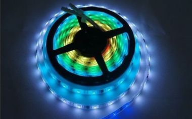
The desire to work with controlled lights using arduino prompted me to build such a system. As it turned out, this is a fairly simple event, for which only a few hours were spent in total (in fact, the building itself - 10 minutes, the rest - software). The details of the assembly process and programming, and I will explain in this article. Software, conclusions and demo attached.
For this illumination we need the following items and devices:
')
The scheme (if this proud word is suitable for connecting two products with four wires) is shown in the figure:
The assembly process is simple to disgrace. It makes no sense to describe it in detail (for the same reason there are no photos of the finished “product” - there are plenty of arduins with four wires on the Internet).
At this assembly is complete. It remains to calculate and set the number of pixels vertically and horizontally, and you can watch videos, play, etc. and rejoice.
The software part consists of two components:
In Arduino, you need to fill in the code below. The SmallUART library is used (which, however, does not do anything particularly outstanding, if you wish, you can do with standard tools).
It's all very simple:
It seems to be ready-made solutions for this, but I did not like what I saw categorically, and in general it is unsportsmanlike, for good reason that something is being used. Therefore, chewing a sandwich, with the left foot a program was written to capture screen areas, process them and transfer the necessary data to the tape. The whole program with giblets is available on the github at github.com/sergrt/pixie (do not kick for the code).
Qt 5.0.1 is used -for the sake of interest, no special things inherent in this particular version are involved, so it will work quite well and the last 4 edits are made using new classes, so now the source code is not compatible with version 4. Since most of my entertainment I do under Windows, the project is made for it - Visual Studio 2012, GDI or DirectX capture. I honestly tried to generate .pro files for Qt Creator, but this process is terribly buggy with the new VS Qt Add-in, as a result, these files did not work right away, I didn’t understand it. But everything can be compiled without problems under linux, see UPD # 3.
The main setting is the indication of the number of LEDs vertically and horizontally, as well as the setting of the sizes of the areas to be captured. In my 22 "fit 10 pieces vertically and 17 horizontally:

The frame rate limit is reasonably set to about 30. The value “0” is used to operate at the highest possible speed.
You also need to correctly specify the port for exchange with Arduino and the rate of exchange. The speed in the default sketch is 115200:

To adjust the brightness, threshold and limiter made a separate tab "Processing". The parameters presented there are adjusted in real time:

For convenience, the program can be configured to auto-capture at startup, as well as run minimized to the notification area.
The main idea is to start a stream that grabs areas by a given mechanism, with adjustable fps, and transfers these areas for processing and subsequent transfer to the tape. Areas are captured in accordance with the settings (who would have thought), the color of the pixel is determined by a simple average of the three RGB channels of the corresponding screen area. Optionally, you can enable (with preprocessor directives) conversion to Lab and averaging it by forces, but this piece of code is not optimized in any way (taken as it is from the Internet), slows down, therefore it is turned off by default. Moreover, Lab does not see any particular advantages in the context of this task, so this is not a reason to be sad.
The areas are processed vertically and horizontally, and a sequence of colors is sent to the tape, starting from the bottom left corner and then around the perimeter in a clockwise direction (as we wrapped the tape on the monitor during assembly).
DirectX capture is approximately equal in speed to capture with GDI, despite the fact that in the first case the entire screen is captured, and in the second - only the necessary pieces. Probably there is an optimization margin.
The abundant use of memcpy is primarily due to the speed of work - all other methods have shown themselves to be slower to one degree or another.
The brightness margin of the tape is just huge, which is good - you can use it even if there are other light sources. In complete darkness, it is better to move the sliders and make it softer. The tape itself may well serve as an independent source of lighting, you only need to redo the sketch.
I suppose the monitor / TV diagonal is of considerable importance. The bigger, the better.
You should also install the screen so that there are no surfaces nearby that reflect the LEDs (in my case these are the side surfaces of the speakers) - this is not particularly critical, but it’s better that the sharply distinguished pixels are not visible at all - because there is a fair distance between them This is not the best way to affect the picture.
What you liked:
Watching video and games with this kind of illumination subjectively unloads the eyes - the hard focus on the picture of the monitor disappears. The feeling of tired eyes comes later, if you do not overdo it with brightness. Watching video is at least unusual, for completeness, it is better to do it from a certain distance.
What did not like:
There are no particular complaints about the illumination system itself, but, as already mentioned, for complete pleasure, you need the right environment - there are no glare surfaces, a uniform background color behind the screen, etc. During the operation, it turned out that the design delights of my monitor somewhat hinder the normal operation of the ribbon - the front panel is made of transparent plastic and protrudes several millimeters above the back cover, especially protruding from the bottom. Therefore, despite the fact that the tape is fixed relatively far away, separate LEDs are visible on the edges of this panel. I suppose few people will face this, but still let the information be available in advance.
Below is a video of how it looks in dynamics. The operator apologizes for the littered horizon.
PS In order to observe propriety, I provide a link to the starting point where I started from - compcar.ru/forum/showthread.php?t=9462
UPD # 1 The software has been updated on the githaba (including the executable file) - the ability to group LEDs has been added to soften the effect when watching movies that are not particularly dynamic.
UPD # 2 Added Qt screen capture support (using QScreen), so now you can build a cross-platform application. The presence of those willing to help test is welcome.
UPD # 3 Thanks to the help of eugenis ( https://github.com/eugenis ), a full-fledged pro project file appeared, inaccuracies were corrected for proper compilation under linux, the code was slightly optimized. All these joys are available on the githab.
The desire to work with controlled lights using arduino prompted me to build such a system. As it turned out, this is a fairly simple event, for which only a few hours were spent in total (in fact, the building itself - 10 minutes, the rest - software). The details of the assembly process and programming, and I will explain in this article. Software, conclusions and demo attached.
Hardware
For this illumination we need the following items and devices:
- LED strip on chips WS2801 (with individual control of each pixel) of the desired length. This tape looks like this:

It is better to buy a tape in a silicone shell. I bought on ebay , you can try to buy directly from the Chinese, it will be cheaper one and a half times. The length of the tape should be sufficient to wrap it around the perimeter around the monitor or TV. - Arduino nano (or one of the many clones) - for example, this one . It will fit and not nano, you only need to properly connect.
- Wires, called DuPont - I do not know how they are called in Russian, they look like this:

These wires are needed for soldering to the tape and connecting to arduino. We need only 2pcs - since they are crimped from two sides, cutting in half we get the necessary 4 wires with connectors. - A 5V power supply unit + a power connector suitable for this unit - both are sold in abundance both in radio stores and on ebay, of any color, size and design.
The tape consumes about 2A / meter in the brightest mode possible. In daily work, 2 meters of tape feed from BP 3A without any problems. - Soldering iron (any, within reasonable limits), soldering accessories, knife for stripping wires, electrical tape / heat shrink to taste.
')
The scheme (if this proud word is suitable for connecting two products with four wires) is shown in the figure:
The assembly process is simple to disgrace. It makes no sense to describe it in detail (for the same reason there are no photos of the finished “product” - there are plenty of arduins with four wires on the Internet).
- Solder everything as shown in the diagram.
- Connect the wires to the arduino, connect the arduino itself to the PC, connect the power supply.
- Pour into Arduino sketch (see below), run the executable file on the computer (see the links to the software also below), install the desired COM port in the program.
If you are using Windows Vista / 7, you must turn off Aero. Otherwise, the speed of work is simply deplorable, there is no solution to the problem of low screen capture speed when Aero is on, as I understand it. - Make sure everything works, turn it off.
It should be mentioned that the software works in 32-bit color only . This can be easily corrected, but in my opinion, there is not much point in such an edit. - Attach the tape to the monitor. You need to start the tape from the lower left corner around the perimeter in a clockwise direction (LN-> LV-> PV-> Mon-> LN). There is no need to cut, the tape bends well almost anywhere, so there should be no problems. For fixing, I used double-sided tape - the tape is very light and this is more than enough.
At this assembly is complete. It remains to calculate and set the number of pixels vertically and horizontally, and you can watch videos, play, etc. and rejoice.
Software part
The software part consists of two components:
- Sketch for Arduino;
- PC control program.
Sketch for Arduino
In Arduino, you need to fill in the code below. The SmallUART library is used (which, however, does not do anything particularly outstanding, if you wish, you can do with standard tools).
/*** ARDUINO CODE FOR PIXEL LIGHT ***/ #include <SPI.h> #include <SmallUart.h> unsigned long lastTime; // Time strip was updated last time const unsigned long fadeTimeout = 3000; //////////////////////////////////////////////////////////// // void setup() { UART_Init(115200); SPI.begin(); SPI.setBitOrder(MSBFIRST); SPI.setDataMode(SPI_MODE0); SPI.setClockDivider(SPI_CLOCK_DIV8); blackoutAll(); delay(1); lastTime = millis(); } //////////////////////////////////////////////////////////// // void loop() { uint8_t data; UART_SendByte( 'R' ); // Byte "We're ready" bool valid = false; data = uartRead( valid ); if ( valid ) { uint16_t pix_num = data * 3; // Total following bytes for( uint16_t i=0; i < pix_num; i++ ) { data = uartRead( valid ); if ( !valid ) break; SPI.transfer( data ); // Transfer byte to SPI } lastTime = millis(); } if ( millis() - lastTime > fadeTimeout ) blackoutAll(); } //////////////////////////////////////////////////////////// // Turn off all possible 256 leds void blackoutAll() { for ( int16_t i = 0; i < 768; i++ ) SPI.transfer( 0 ); // } //////////////////////////////////////////////////////////// // Read byte with timeout unsigned char uartRead( bool& valid ) { uint8_t res = 0; valid = false; for ( uint8_t i = 0; i < 255; ++i ) { // Max timeout 256*10 if( UART_ReadByte( res ) ) { valid = true; break; } delayMicroseconds(10); } return res; } It's all very simple:
- We send a signal that we are ready to accept backlight data;
- We expect data for a short time;
- If the data came, then the first byte of this data is the number of diodes that are served. Multiply by 3 (RGB) in order to find out the number of subsequent bytes;
- We forward the received data to the tape;
- Update the timestamp of the latest tape update (this is necessary for the timeout and blanking of all pixels of the tape).
PC software
It seems to be ready-made solutions for this, but I did not like what I saw categorically, and in general it is unsportsmanlike, for good reason that something is being used. Therefore, chewing a sandwich, with the left foot a program was written to capture screen areas, process them and transfer the necessary data to the tape. The whole program with giblets is available on the github at github.com/sergrt/pixie (do not kick for the code).
Qt 5.0.1 is used -
Program settings
The main setting is the indication of the number of LEDs vertically and horizontally, as well as the setting of the sizes of the areas to be captured. In my 22 "fit 10 pieces vertically and 17 horizontally:
The frame rate limit is reasonably set to about 30. The value “0” is used to operate at the highest possible speed.
You also need to correctly specify the port for exchange with Arduino and the rate of exchange. The speed in the default sketch is 115200:
To adjust the brightness, threshold and limiter made a separate tab "Processing". The parameters presented there are adjusted in real time:
For convenience, the program can be configured to auto-capture at startup, as well as run minimized to the notification area.
A little about the insides of software for those interested
The main idea is to start a stream that grabs areas by a given mechanism, with adjustable fps, and transfers these areas for processing and subsequent transfer to the tape. Areas are captured in accordance with the settings (who would have thought), the color of the pixel is determined by a simple average of the three RGB channels of the corresponding screen area. Optionally, you can enable (with preprocessor directives) conversion to Lab and averaging it by forces, but this piece of code is not optimized in any way (taken as it is from the Internet), slows down, therefore it is turned off by default. Moreover, Lab does not see any particular advantages in the context of this task, so this is not a reason to be sad.
The areas are processed vertically and horizontally, and a sequence of colors is sent to the tape, starting from the bottom left corner and then around the perimeter in a clockwise direction (as we wrapped the tape on the monitor during assembly).
DirectX capture is approximately equal in speed to capture with GDI, despite the fact that in the first case the entire screen is captured, and in the second - only the necessary pieces. Probably there is an optimization margin.
The abundant use of memcpy is primarily due to the speed of work - all other methods have shown themselves to be slower to one degree or another.
Conclusions and impressions
The brightness margin of the tape is just huge, which is good - you can use it even if there are other light sources. In complete darkness, it is better to move the sliders and make it softer. The tape itself may well serve as an independent source of lighting, you only need to redo the sketch.
I suppose the monitor / TV diagonal is of considerable importance. The bigger, the better.
You should also install the screen so that there are no surfaces nearby that reflect the LEDs (in my case these are the side surfaces of the speakers) - this is not particularly critical, but it’s better that the sharply distinguished pixels are not visible at all - because there is a fair distance between them This is not the best way to affect the picture.
What you liked:
Watching video and games with this kind of illumination subjectively unloads the eyes - the hard focus on the picture of the monitor disappears. The feeling of tired eyes comes later, if you do not overdo it with brightness. Watching video is at least unusual, for completeness, it is better to do it from a certain distance.
What did not like:
There are no particular complaints about the illumination system itself, but, as already mentioned, for complete pleasure, you need the right environment - there are no glare surfaces, a uniform background color behind the screen, etc. During the operation, it turned out that the design delights of my monitor somewhat hinder the normal operation of the ribbon - the front panel is made of transparent plastic and protrudes several millimeters above the back cover, especially protruding from the bottom. Therefore, despite the fact that the tape is fixed relatively far away, separate LEDs are visible on the edges of this panel. I suppose few people will face this, but still let the information be available in advance.
Below is a video of how it looks in dynamics. The operator apologizes for the littered horizon.
Links
- Github Project - github.com/sergrt/pixie
- Archive with executable file for Win7 / Vista etc - rghost.net/43638571 (VS 2012, Qt5)
- Archive with an executable file for Windows XP - www.filedropper.com/pixiexp (VS 2010, Qt4 - works on XP, cross-platform locking is disabled - because some of the necessary classes are missing in Qt4)
- Link to Visual Studio 2012 Update 1 Redistributable Package (in case of errors with the absence of msvcp110.dll files, etc.) - www.microsoft.com/en-us/download/details.aspx?id=30679
- Visual C ++ 2010 SP1 Redistributable Package (x86) Link (for Windows XP version) - www.microsoft.com/en-us/download/details.aspx?id=8328
PS In order to observe propriety, I provide a link to the starting point where I started from - compcar.ru/forum/showthread.php?t=9462
UPD # 1 The software has been updated on the githaba (including the executable file) - the ability to group LEDs has been added to soften the effect when watching movies that are not particularly dynamic.
UPD # 2 Added Qt screen capture support (using QScreen), so now you can build a cross-platform application. The presence of those willing to help test is welcome.
UPD # 3 Thanks to the help of eugenis ( https://github.com/eugenis ), a full-fledged pro project file appeared, inaccuracies were corrected for proper compilation under linux, the code was slightly optimized. All these joys are available on the githab.
Source: https://habr.com/ru/post/168657/
All Articles