Theory and practice of passive pyroelectric sensors or how to make an indicator of the direction of movement
In our imperfect world, various technical things are highly demanded, designed to guard the property and tranquility of citizens. Therefore it is difficult, I believe, to find a person who would never see security alarms equipped with motion sensors. The physical principles of their work, as well as the implementation may be different, but it is probably the most common pyroelectric passive infrared sensors (PIR).
Some such: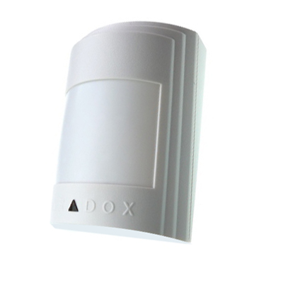
They react to changes in radiation in the infrared range, namely in its middle part - 5-15 microns (the body of an average healthy person radiates in the range of about 9 microns). From the point of view of the end user, the piece is very simple - a power input (usually 12 volts) and a relay output (usually solid-state and with normally closed contacts). Somebody sneaked past by - the relay worked. Boredom. But inside is not so simple.
Today we will devote a little time to theory, and then gut one such device and make it not just a sensor that reacts to the fact of movement, but records the direction of movement.
')
Some theory
Some crystalline substances have the property of polarizing under the action of radiation incident on them. With a change in the intensity of radiation, the polarization also changes, and, consequently, the electric field intensity in the crystal. Hence the name - pyroelectrics. Further, by measuring the potential difference between different points of the crystal, it is possible to judge the magnitude of the radiation. True, the potential difference arising is rather quickly compensated by “sticking” to the crystal with charged particles, which are sufficient in the surrounding space. For this reason, pyroelectric is not very suitable for measuring the constant intensity of radiation. This is precisely the change in radiation that can be recorded. But for the purposes in which such sensors are used - motion fixation, this is what is needed.
It seems simple, but there is a small problem. We are not interested in changing radiation at all, but it is interesting to change it because of the intruder’s passage. But the sun rises and sets, summer gives way to winter, heating is turned on and off, and the infrared radiation falling on the sensor varies within very large limits, although no one has thought to encroach on our property. It is clear that the practical value of the device that reacts to anything, is close to zero. Bypassing this trouble is quite simple - instead of one sensitive element, two are used. Including them in a chain consistently so that changes in tension on them occur in opposite directions. And constructively arranging so that the “global” change in the level of infrared radiation (say, with a change in air temperature) affects them equally, and the “local” (movement of an object like a person) in a different one. To make it clearer, let's move on to an illustration (the drawings are intentionally made by hand, in order to somewhat diversify the dominance of computer graphics).
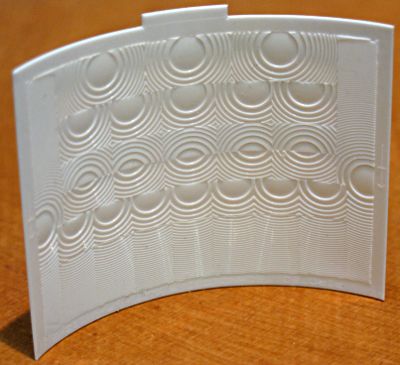
Inside the metal case (shown in blue) are placed two pyroelectric crystals. For the measured radiation in the body there is a window closed by a filter (red), which passes only the wavelength range we need. In front of the window is placed the optical system (green), forming the desired radiation pattern of the sensor. Biconvex lens is drawn, of course, conditionally. Real sensors use Fresnel lenses stamped on plastic (transparent in the necessary frequency range, of course). Like these ones:
About lenses more later.
Right next to the crystals inside the case (in order not to lose the measured value in the "long road"), a field effect transistor is placed, the drain and source of which are already brought outside. Field transistor for good reason. This device, as is known, is controlled by an electric charge, the change of which on a crystal is actually measured by us. The bipolar transistor here would absolutely not fit, as a device controlled by a current, which the pyroelectric can not issue. The resistor is needed to drain parasitic static charges, although it somewhat degrades the sensitivity of the device.
Now about the lenses. Without lenses, the sensor has a very wide radiation pattern - 100-120 ° vertically and horizontally. At the same time (conditionally) one half of the space is “seen” by one crystal, the other - by the other. Those. it turns out such a cone, cut by a plane, the direction of which depends on the relative position of the crystals. Usually this plane is vertical. With the help of a lens, two relatively narrow “beams” of the radiation pattern are formed from the two resulting half-cones. This increases the distance sensitivity of the sensor and reduces parasitic noise. However, the narrowness of the diagram leads to the ability of the intruder to easily bypass the sensitive areas. To prevent this from happening, the lenses make several (this is just seen in the photo above) and, accordingly, form several pairs of rays. Their appearance and number depend on the field of application of the sensor. Let's say for the corridors you need to "see" narrowly, but far. For square rooms - close and wide. Somewhere you need to protect the area under the sensor, somewhere above it, etc. But this is all not important, so we will focus on one pair of rays that a moving warm object crosses.
As it moves, the object will fall into the field of view of a single crystal, and it will form a voltage pulse in accordance with changes in the level of infrared radiation. When an object falls into the field of view of another crystal, it will also generate an impulse, but of a different direction (we remember that the crystals are included in the opposite polarity). If an object crosses several pairs of rays, then this whole process will repeat.
Note: Due to the fact that the power supply of the sensor, as a rule, is unipolar, one cannot speak of a positive and negative impulse. You can only talk about the change in voltage up or down from a certain average value of "rest", depending on the parameters of the sensor, its switching circuit, and the state of the environment. But for the sake of convenience, we will speak about negative and positive impulses.
From this point on, it becomes clear how to determine the direction of movement. If a positive impulse is recorded first, and then a negative one, then the direction is one; if, on the contrary, it is another. However, in the household sensors, which we are talking about, this property is not used. But then we fix it.
It is impossible to use the signal directly from the sensor - it is too small, and its average value “floats” within wide limits. The signal needs to be strengthened, and hundreds of thousands of times, to get rid of the mean value drift and convert to a discrete form — there is movement / no movement. A typical block diagram of a motion sensor that solves these problems has the following form:
The weak signal of the sensor is amplified and fed to a pair of comparators, one of which records the excess of the specified amplitude with a positive pulse, the second - with a negative pulse. An already discrete signal from the comparators is sent to the actuator. The last one is usually the waiting multivibrator, which for some fixed time turns on the relay, and then it already opens / closes the security loop. In more advanced sensors, instead of comparators, there can be more complex schemes that provide protection against false alarms, sharp fluctuations in environmental parameters, actuations from the movement of small animals, additional reaction to a fire, etc. In most modern sensors, all this is not done by analog circuits and DSP.
However, to achieve this goal, we will be interested only in what is up to the comparator. Those. the amplifying part, and more specifically, the output of the already amplified signal of the pyroelectric sensor. In order to be able to find this place in the disassembled sensor, let's see what needs to be looked for. And you need to search first of all the op-amp chips (OU), located near the sensor.
A typical amplifier circuit looks like this (drawn approximately, since variations of specific versions are not considered):
In this case, the first stage is a non-inverting amplifier, the second inverting. The gains of each of them are about tens of thousands, and both are of the order of hundreds of thousands. But the main “secret” is that the OU feedbacks contain elements (namely, capacitors) that make these connections dependent on frequency. The element ratings are such that near zero frequency (direct current), the overall gain tends to zero, near the frequency of 5 hertz there is a gain maximum, and at frequencies above 10 hertz again tends to zero. This frequency response is not random. The size of the area that captures our pair of rays, about 0.5-1 meters. The speed of movement of a person is about 1-3 m / s. Accordingly, the frequency of intersection of sensitive zones will be just units of hertz. And the signals lying outside this range can be considered parasitic. Including the drift of the constant component of the signal. Those. in the giblets of the sensor you need to look for something like the output of the second gain stage.
Go to the practical exercises.
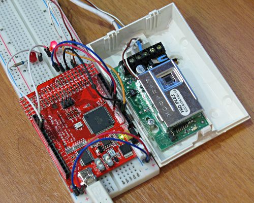
Having armed with theoretical information we will get a soldering iron. The photo shows a disassembled sensor (removed the front cover with Fresnel lenses and a metal screen).

We look at the marking of the closest to the pyroelectric sensor (a round metal with a window - this is it) of the microcircuit and (oh, good luck!) It turns out to be the LM324 - quad op amp. By looking at the surrounding elements, we find the output of an opamp that is most likely suitable for our purposes (in my case, this turned out to be output 1 of the microcircuit). Now it would be nice to check, and whether we found. Usually, an oscilloscope is used for this. I did not have it at hand. But it turned out to be arduino. Since the signal level after amplification is of the order of units of a volt, and we don’t need special measurement accuracy (a sufficiently qualitative assessment), the Arduino ADC inputs are fine. To the found OU output and the power supply minus we solder the wiring and output it to the layout board. Wires should not be long. Otherwise, there is a chance to measure not the sensor signal, but something completely different.
Now let's think about how fast the signal needs to be read in order to get something sane. Above it was said that the frequency range of the useful signal is limited to approximately 10 Hz. Recalling the Kotelnikov theorem (or Nyquist - who likes what more), we can conclude that there is no sense in measuring the signal with a frequency higher than 20 Hz. Those. A sampling period of 50 ms is fine. We write a simple sketch that reads port A1 every 50 ms and dumps its value into the series (strictly speaking, signal measurements occur less frequently than 50 ms, since it also takes time to write to the port, but for our purposes this is not important).
unsigned long time; void setup() { Serial.begin(9600); pinMode(A1, INPUT); time=millis(); } void loop() { if ((millis()-time) >= 50) { Serial.println(analogRead(A1)); } time=millis(); } We turn on and wave our hands in front of the sensor (you can run, even more useful). On the side of the computer, the data from the port is dumped into a file.
stty -F /dev/ttyUSB0 raw ispeed 9600 ospeed 9600 -ignpar cs8 -cstopb -echo cat /dev/ttyUSB0 > output.txt Build a graph (a column with numbering counts has been added to the file):
gnuplot> plot "output.txt" using 1:2 with lines 
And we see what, in fact, wanted to - bipolar voltage surges. Hooray, the theory works and the wire is soldered where necessary. A simple analysis (in other words, a review) of the graph allows us to conclude that the deviation of the signal by 150 units from the average value can be considered as a more or less reliable fixation of the presence of motion.
It is time to finally make the direction sensor.
Modify the scheme. In addition to the analog signal of the sensor, we will connect a pair of LEDs to Arduino (ports 2 and 3, do not forget the current-limiting resistors) and write a slightly more complex sketch.
Expand
int a1; int state2=0; long average=0; int n=0; unsigned long time; void setup() { pinMode(2, OUTPUT); pinMode(3, OUTPUT); pinMode(A1, INPUT); digitalWrite(2, LOW); digitalWrite(3, LOW); delay (30000); // // 30 . time=millis(); // // // while (n <= 1000) { ++n; a1=analogRead(A1); average=average+a1; delay(50); } average=average/1000; // //, digitalWrite(2, HIGH); digitalWrite(3, HIGH); delay(1000); digitalWrite(2, LOW); digitalWrite(3, LOW); time=millis(); } void loop() { // 50 if ((millis()-time) >= 50) { // // -1/0/1 a1=(analogRead(A1)-average)/150; // , // switch (a1) { case 1: if (state2=-1) {digitalWrite(2, HIGH);digitalWrite(3, LOW);} state2=a1; break; case -1: if (state2=1) {digitalWrite(2, LOW);digitalWrite(3, HIGH);} state2=a1; break; } // time=millis(); } } In order to leave only one pair out of the entire set of rays of the radiation pattern of the sensor, we close all but one Fresnel lens with a paper screen.

Enjoying the result.
Source: https://habr.com/ru/post/167201/
All Articles