Triac power controller with microcontroller control
Once, for one small home project, I needed a power regulator suitable for adjusting the rotational speed of an AC electric motor. As a basis, such a board based on the STM32F103RBT6 microcontroller was used. The board was chosen as having an honest RS232 interface and having at the same time a minimum of additional components. There is no slot for a lithium battery on the board to power the clock, but to live on it is a matter of fifteen minutes.
So let's start with the theory. Everyone is familiar with the so-called pulse-width modulation , which allows to control the current in (or, more rarely, the voltage on) the load with maximum efficiency. The excess power in this case simply will not be consumed, instead of being dissipated as heat, as in the case of linear regulation, which is nothing more than a complicated version of the rheostat. However, for a number of reasons, such control, being performed head-on, is not always suitable for alternating current. One of them is the greater circuit complexity, since a diode bridge is required to power the power section on MOSFET or IGBT transistors. These shortcomings are deprived of a triac control, which is a modification of PWM.
Triac ( TRIAC in the English literature) is a semiconductor device, a modification of the thyristor, designed to work as a key, that is, it can be either open or closed and does not have a linear mode of operation. The main difference from a thyristor is bilateral conduction in the open state and (with some reservations) independence from current polarity (thyristors and triacs are controlled by current, as well as bipolar transistors) through the control electrode. This makes it easy to use a triac in AC circuits. The second feature, common with thyristors, is the property of maintaining conductivity when the control current disappears. The triac closes when the current is disconnected between the main electrodes, that is, when the alternating current passes through zero. A side effect of this is to reduce noise when disconnecting. Thus, to open the triac, it is enough for us to apply a small opening pulse of the order of tens of microseconds to the control electrode, and it closes itself at the end of the half-cycle of alternating current.
The triac control takes into account the above properties of this device and consists in unlocking the triac on each half-period of alternating current with a constant delay relative to the point of zero crossing. Thus, a “slice” is cut from each half-period. The part shaded in the figure is the result of this procedure. Thus, instead of a sinusoid, we will have something that resembles a saw to a certain degree:
')

Now our task is to unlock the triac in time. We will assign this task to the microcontroller. The scheme below is the result of an analysis of existing solutions as well as documentation for optocouplers. In particular, the power unit is taken from the documentation for a triac optocoupler manufactured by Texas Instruments. The circuit is not without flaws, one of which is a powerful wire resistor-stove, through which an optocoupler is turned on, detecting a zero crossing.
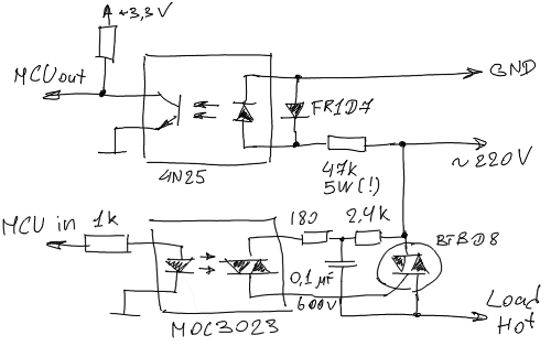
How it works? Consider drawing.
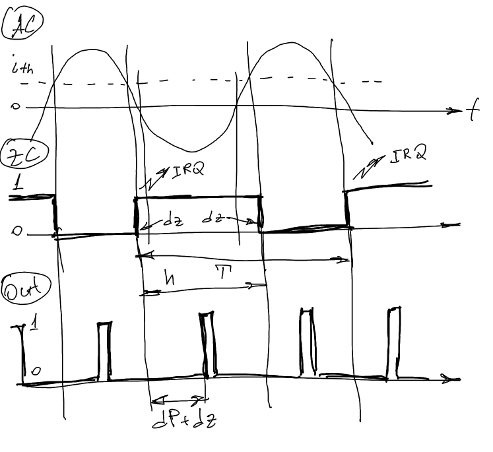
On the positive half-period, when the current through the optocoupler exceeds a certain threshold value, the optocoupler opens and the voltage at the input of the microcontroller drops to almost zero (the “ZC” curve in the figure). When the current falls below this value again, one is sent to the microcontroller again. This happens at time points, separated by dz from zero current. This dz is palpable, in my case it is about 0.8 ms, and it must be taken into account. This is easy: we know the period T and the duration of the high level pulse h, whence dz = (h - T / 2) / 2. Thus, we need to open the triac through dz + dP from the leading edge of the signal from the optocoupler.
About phase shift dP worth talking separately. In the case of c PWM DC, the average value of the output current will depend linearly on the duty ratio of the control signal. But this is only because the integral of the constant gives a linear relationship. In our case, it is necessary to build on the value of the sine integral. The solution of a simple equation gives us the desired dependence: for a linear change in the average current, it is necessary to change the phase shift according to the law of cosine, for which it is sufficient to enter a table into the LUT control program.
Everything that I will discuss in the future is directly related to the architecture of the STM32 series microcontrollers, in particular, to the architecture of their timers. Microcontrollers in this series have a different number of timers, in the STM32F103RBT6 there are seven of them, four of which are suitable for capturing and generating PWM. Timers can be cascaded: for each timer, one of the internal events (overflow, reset, level change on one of the input or output channels, etc .; refer you to the documentation for details) can be declared a holiday and sent to another timer by assigning it to it has a specific action: start, stop, reset, etc. We will need three timers: one of them, working in the so-called. PWM input mode, measures the period of the input signal and the duration of the high level pulse. At the end of the measurement, after each period an interrupt is generated. At the same time, the phase shift timer associated with this event is started, operating in standby mode. Upon an overflow event, this timer is forced to reset the timer, which generates the output control signal to the triac, so that after each full period of alternating current, the phase of the control signal is adjusted. Only the first timer generates an interrupt, and the task of the handler is reduced to adjusting the phase shift (ARR register of the waiting timer) and the PWM period of the timer (also the ARR register) so that it is always equal to half the AC period. Thus, all management takes place at the hardware level and the influence of software delays is completely excluded. Yes, it could have been done programmatically, but it was a sin not to take advantage of such an opportunity as cascaded timers.
I don't see the point of putting the entire project code on display, and besides, it is far from complete. I will cite only a fragment containing the algorithm described above . It is completely independent of other parts and can easily be ported to another project on a compatible microcontroller.
And finally, a video showing the device in action:
So let's start with the theory. Everyone is familiar with the so-called pulse-width modulation , which allows to control the current in (or, more rarely, the voltage on) the load with maximum efficiency. The excess power in this case simply will not be consumed, instead of being dissipated as heat, as in the case of linear regulation, which is nothing more than a complicated version of the rheostat. However, for a number of reasons, such control, being performed head-on, is not always suitable for alternating current. One of them is the greater circuit complexity, since a diode bridge is required to power the power section on MOSFET or IGBT transistors. These shortcomings are deprived of a triac control, which is a modification of PWM.
Triac ( TRIAC in the English literature) is a semiconductor device, a modification of the thyristor, designed to work as a key, that is, it can be either open or closed and does not have a linear mode of operation. The main difference from a thyristor is bilateral conduction in the open state and (with some reservations) independence from current polarity (thyristors and triacs are controlled by current, as well as bipolar transistors) through the control electrode. This makes it easy to use a triac in AC circuits. The second feature, common with thyristors, is the property of maintaining conductivity when the control current disappears. The triac closes when the current is disconnected between the main electrodes, that is, when the alternating current passes through zero. A side effect of this is to reduce noise when disconnecting. Thus, to open the triac, it is enough for us to apply a small opening pulse of the order of tens of microseconds to the control electrode, and it closes itself at the end of the half-cycle of alternating current.
The triac control takes into account the above properties of this device and consists in unlocking the triac on each half-period of alternating current with a constant delay relative to the point of zero crossing. Thus, a “slice” is cut from each half-period. The part shaded in the figure is the result of this procedure. Thus, instead of a sinusoid, we will have something that resembles a saw to a certain degree:
')
Now our task is to unlock the triac in time. We will assign this task to the microcontroller. The scheme below is the result of an analysis of existing solutions as well as documentation for optocouplers. In particular, the power unit is taken from the documentation for a triac optocoupler manufactured by Texas Instruments. The circuit is not without flaws, one of which is a powerful wire resistor-stove, through which an optocoupler is turned on, detecting a zero crossing.
How it works? Consider drawing.
On the positive half-period, when the current through the optocoupler exceeds a certain threshold value, the optocoupler opens and the voltage at the input of the microcontroller drops to almost zero (the “ZC” curve in the figure). When the current falls below this value again, one is sent to the microcontroller again. This happens at time points, separated by dz from zero current. This dz is palpable, in my case it is about 0.8 ms, and it must be taken into account. This is easy: we know the period T and the duration of the high level pulse h, whence dz = (h - T / 2) / 2. Thus, we need to open the triac through dz + dP from the leading edge of the signal from the optocoupler.
About phase shift dP worth talking separately. In the case of c PWM DC, the average value of the output current will depend linearly on the duty ratio of the control signal. But this is only because the integral of the constant gives a linear relationship. In our case, it is necessary to build on the value of the sine integral. The solution of a simple equation gives us the desired dependence: for a linear change in the average current, it is necessary to change the phase shift according to the law of cosine, for which it is sufficient to enter a table into the LUT control program.
Everything that I will discuss in the future is directly related to the architecture of the STM32 series microcontrollers, in particular, to the architecture of their timers. Microcontrollers in this series have a different number of timers, in the STM32F103RBT6 there are seven of them, four of which are suitable for capturing and generating PWM. Timers can be cascaded: for each timer, one of the internal events (overflow, reset, level change on one of the input or output channels, etc .; refer you to the documentation for details) can be declared a holiday and sent to another timer by assigning it to it has a specific action: start, stop, reset, etc. We will need three timers: one of them, working in the so-called. PWM input mode, measures the period of the input signal and the duration of the high level pulse. At the end of the measurement, after each period an interrupt is generated. At the same time, the phase shift timer associated with this event is started, operating in standby mode. Upon an overflow event, this timer is forced to reset the timer, which generates the output control signal to the triac, so that after each full period of alternating current, the phase of the control signal is adjusted. Only the first timer generates an interrupt, and the task of the handler is reduced to adjusting the phase shift (ARR register of the waiting timer) and the PWM period of the timer (also the ARR register) so that it is always equal to half the AC period. Thus, all management takes place at the hardware level and the influence of software delays is completely excluded. Yes, it could have been done programmatically, but it was a sin not to take advantage of such an opportunity as cascaded timers.
I don't see the point of putting the entire project code on display, and besides, it is far from complete. I will cite only a fragment containing the algorithm described above . It is completely independent of other parts and can easily be ported to another project on a compatible microcontroller.
And finally, a video showing the device in action:
Source: https://habr.com/ru/post/166427/
All Articles